WEEK 03
- 1.-Introduction
- 2.-Characterize materials
- 3.-My firts parametric kit
- 4.-My second model. The General Parametric Kit
- 5.-Vinyl cutting. Final Proyect Logo Sticker
- 6.- My experience and conclusions from WEEK3
Computer Controlled Cutting
Workgroup
LaserCutting
VinylCutting
Fab-Weeks
Are you looking for my assignments?
Links and notes
more information:
Week 03: Computer Controlled Cutting
1.-Introduction:
In this week I have practiced laser cutting of pieces and automatic vinyl cutting. I have worked in a group to characterize materials to work in laser cutting in a correct way.
We have found the press fit for the materials.
In addition, I have created a parametric kit, to manufacture in laser cut. Cardboard has been chosen for its manufacture.
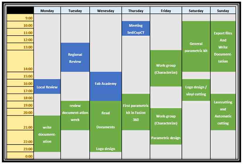
My week journal:
2.-Characterize materials:
If you want to know the group assessment of this week, click on the image of SediCupCt.

3.-My first parametric kit
To do the parametric design I decided to use Fusion 360. In Fusion 360 It is my first time with a parametric model, I worked with parametric models with Solidworks a long time ago but I want know how Fusion works.
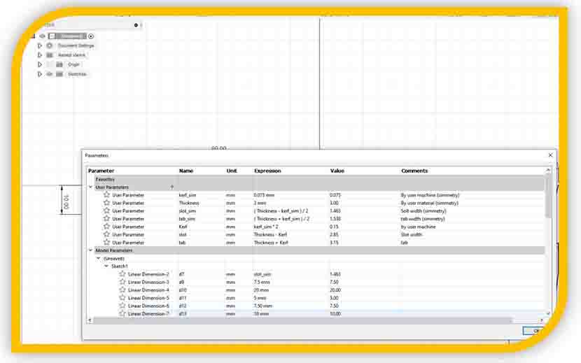
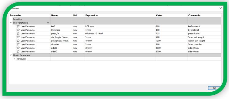
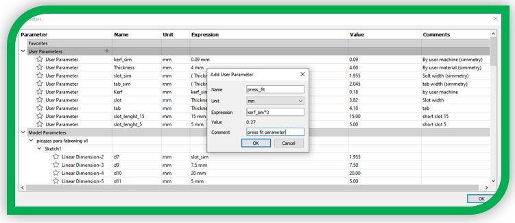
I create my parameter board. In this case, I set the parameters: kerf and kerf to draw in symmetry,
material thickness, slot dependent by material and press fit, tab dependent by material and press fit,
the slots length, and press fit variable of kerf material.
I draw some parts using symmetry. Using this case, I can change one variable in half of my model, and the other half change referring to this part.
Image principal part to symmetry.
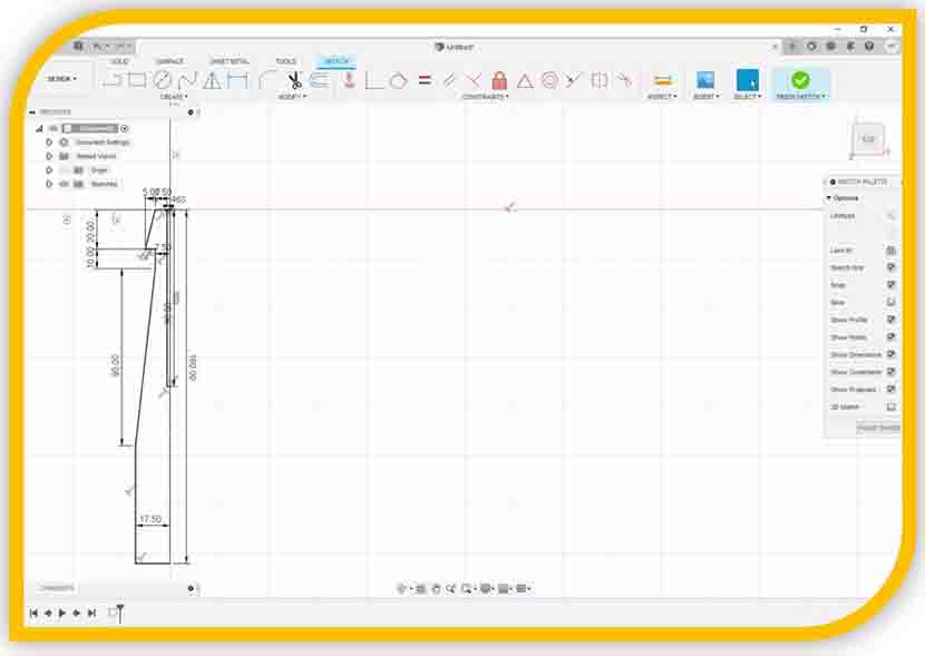
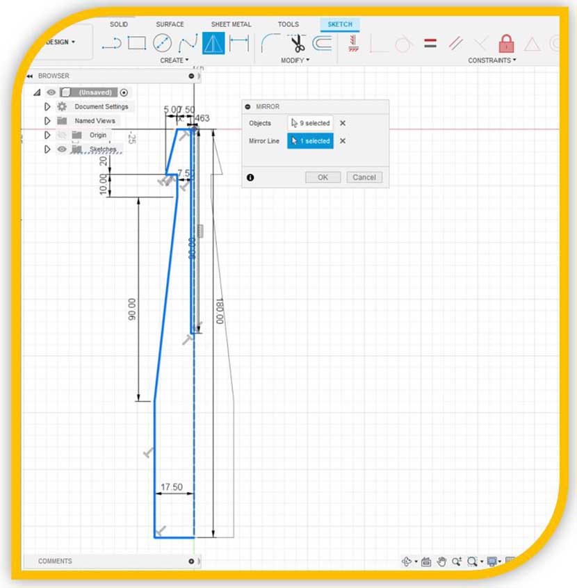
Image operation symmetry:
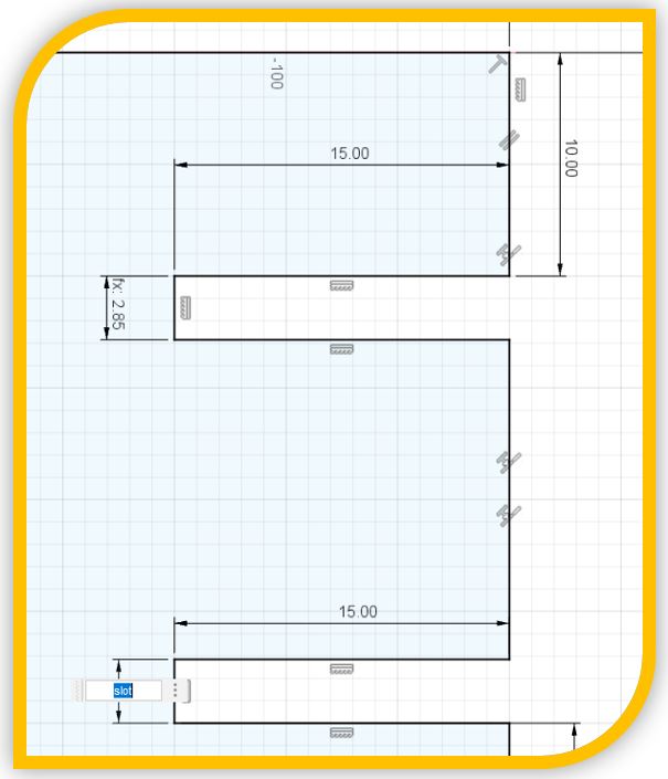
All my slots are set to the press fit parametric ratio. You can see this in the following images.
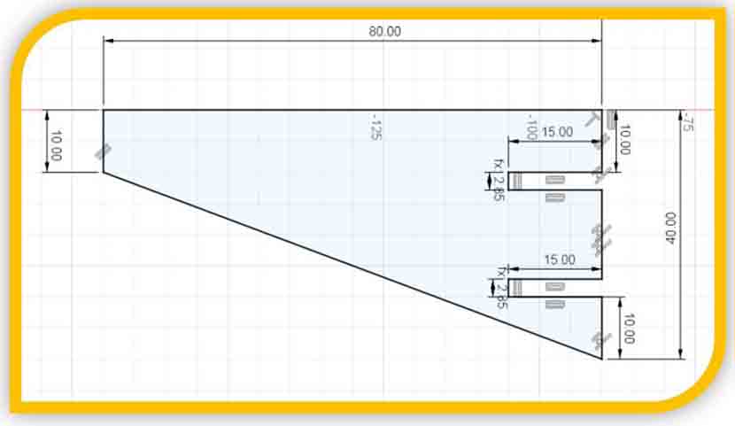
Slot dimension detail:
With all contours drawn, I have to adapt the parameterized dimensions according to the characterization of my material.
I select 4mm cardboard to do this.
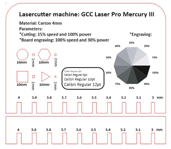
Its kerf is 0.09mm, It was calculated in the workgroup.
So I put this values in my parameters board and I am ready to export in .dwg to lasercutting software.
To validate my design, I extrude the sketch referred to the material thickness parameter and export the parts in
.stl to Solidworks for assembly. I set the material:
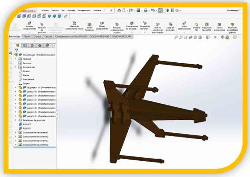
And I do the render assembly.
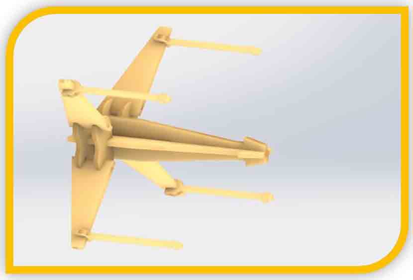
!! IT’S THE SAME!!! XD:
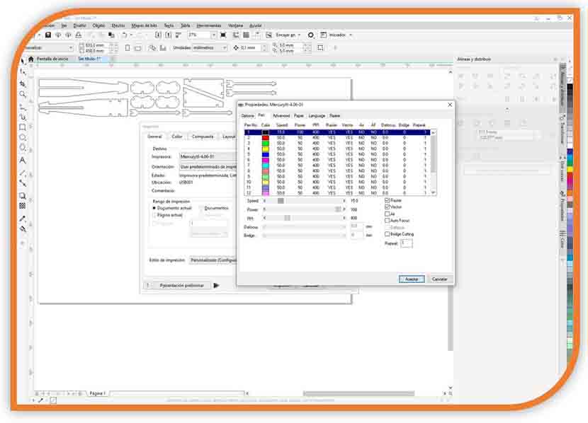
I import the file .dwg in Corel Draw, whith this software I can "print" the desig to cut on the lasercutter.
In the "printer" config, I can select the Mercury III (my cutterlaser) and set the patameters to cut the design on my material.
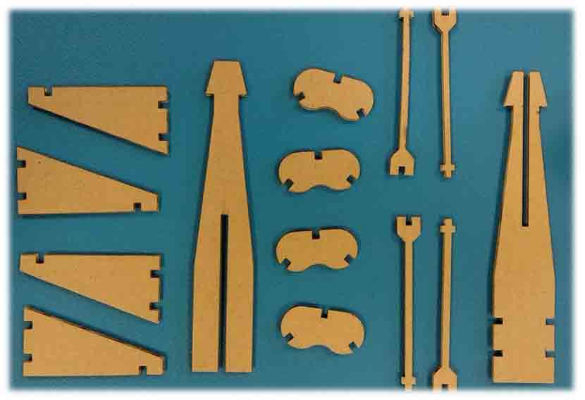
All the parts of my kit are these:
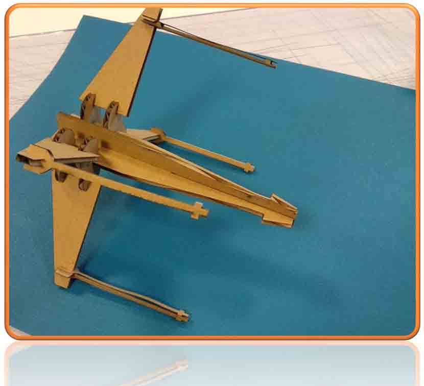
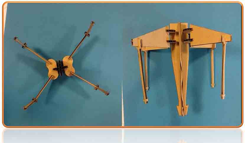
And the assembly is:
4.-My second model. The General Parametric Kit
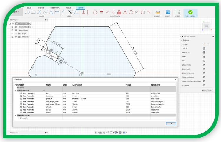
For this Kit, I started creating a new file and setting the parameter board.
I keep working with a kerf of 0.09mm. In addition, I need a press fit, I have observed that the best fit for the cardboard slots is obtained by parameterizing my design with a value of 5 times the kerf (a slot value of 3.55mm, which verifies the fit with the template that is into the 3.5mm slot).
I draw assigning each dimension with its defined parameter. In this kit all the dimensions of the pieces have their control parameter.
I use parameter to draw with symmetry:
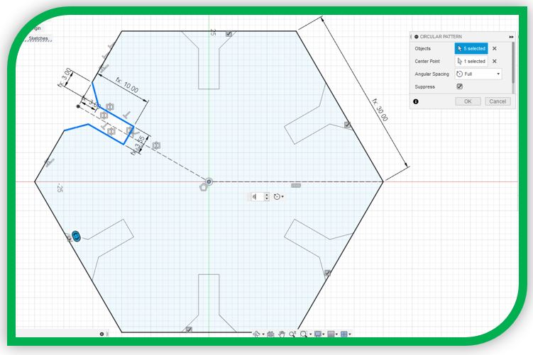
And I get parts faster,
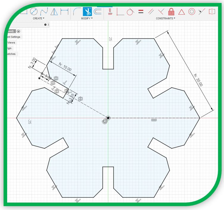
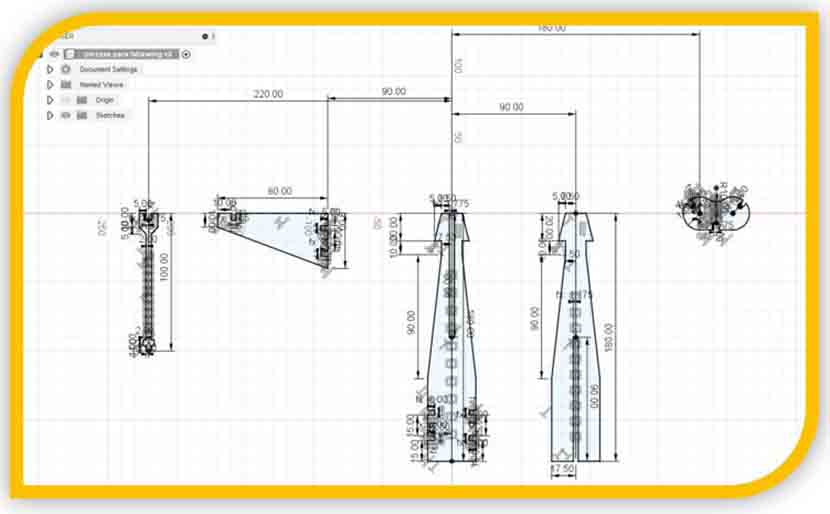
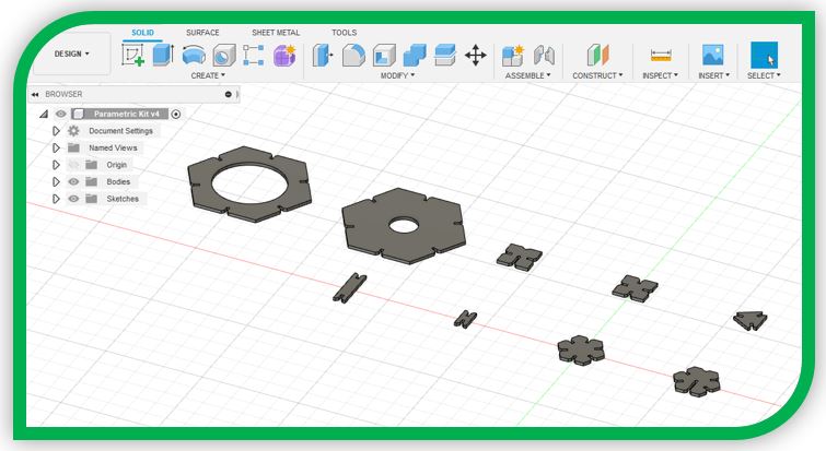
I design all the parametric parts of the kit.
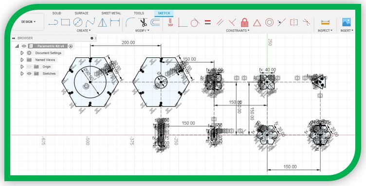
And I extrude the parts based on the thickness parameter to see the 3D models.
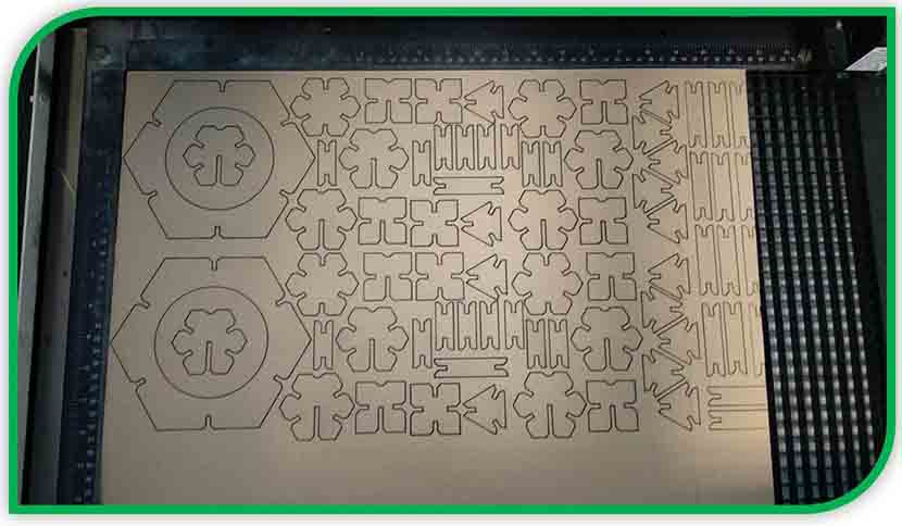
I export the kit in .dwg to lasercutting software.
As with the first kit, I place it, set the parameters in Corel Draw and cut it
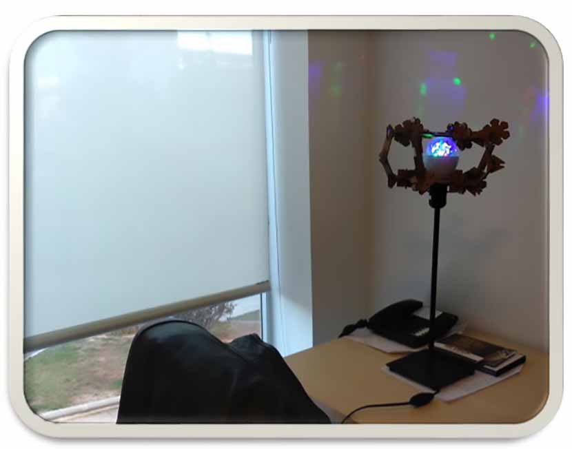
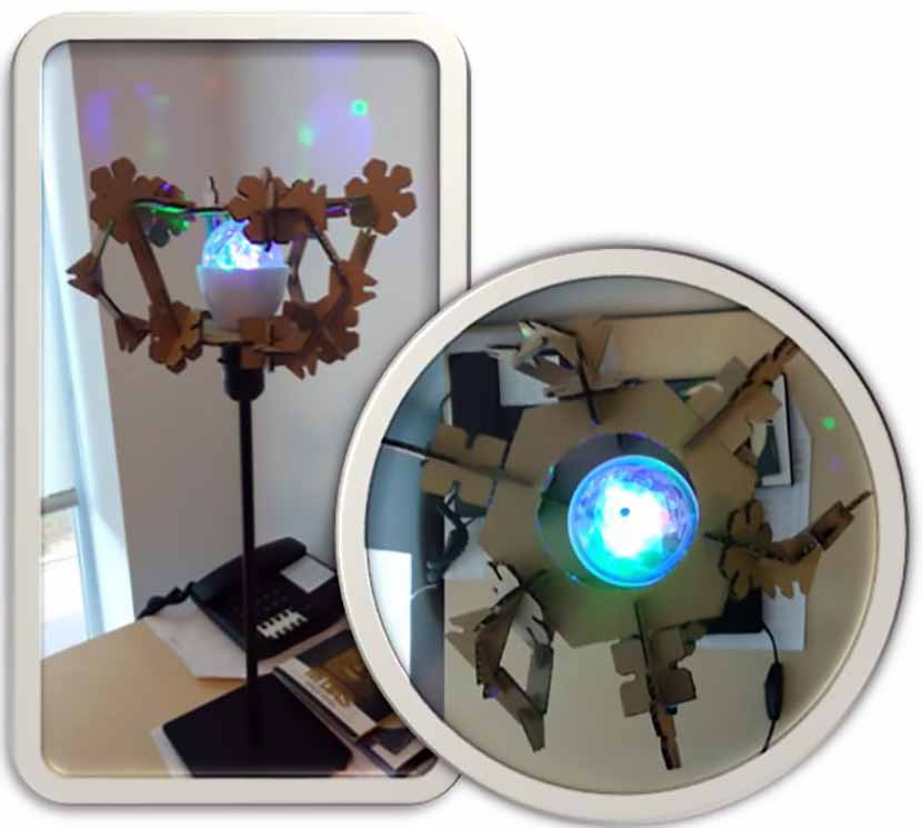
I assemble my kit, multi configuration, in a lamp shape.
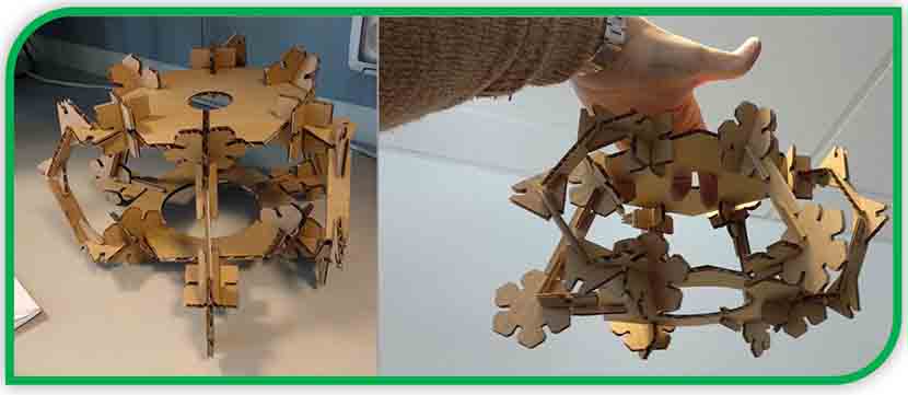
the assembly on a lamp leg would look like this.
5.-Vinyl Cutting. Final Proyect Logo Sticker
I use Illustrator to design my final project logo.
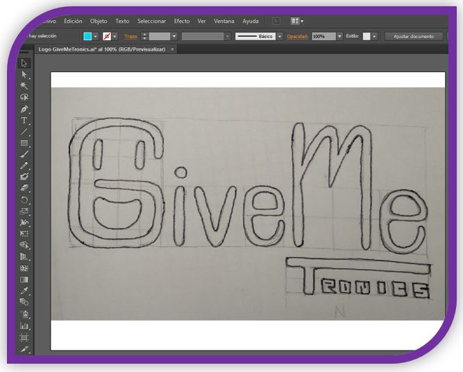
I vectorize the letter "G", it will be my isotype.
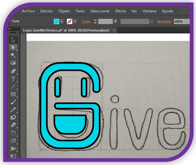
For the main letter font, I use a free font (MV Boli https://www.1001freefonts.com/es/ ) and tweak its style a bit.
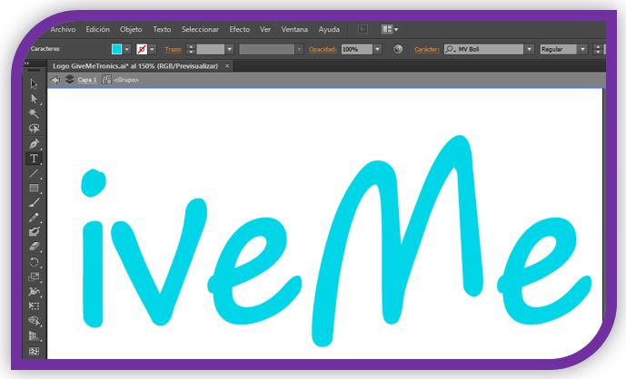
For the secondary letter fount, I design the letters with rectangles and lines.

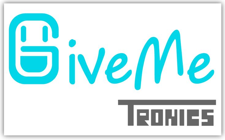
The result is:
Later, I configure the contour lines with a specific type of line that is "CutContour", this type of line indicates in the automatic cutter software what is the way to cut.
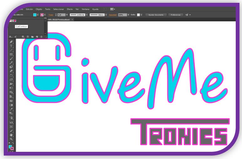
I import this file with the Cutcontour lines at PhosterShop Rip Center to print a sticker and put de automatic lines to detect the area to cut by the automatic-cutter.

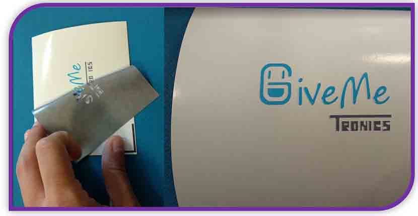
I print the sticker and take it to the automatic cutter
then I remove the negative part of the cutout. I already have my sticker ready!
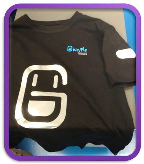
Also, I'm going to make a vinyl cut to put on a t-shirt.
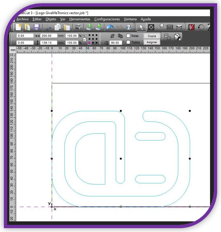
So I export in eps or svg format to GreatCut, the software of the automatic cutter.
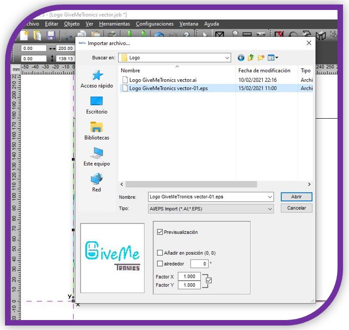
I set the orientation, size and I active the mode mirror,
because the visible area is in the area where the vinyl sticks.
I set the force, number of passes (1 in this case), and I execute the cut
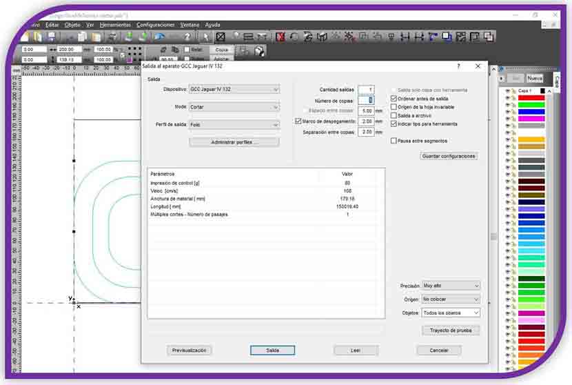
the result is:
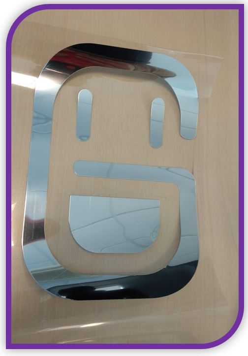
I glued the textile cutting vinyls on a black t-shirt.

6.- My experience and conclusions from WEEK3:
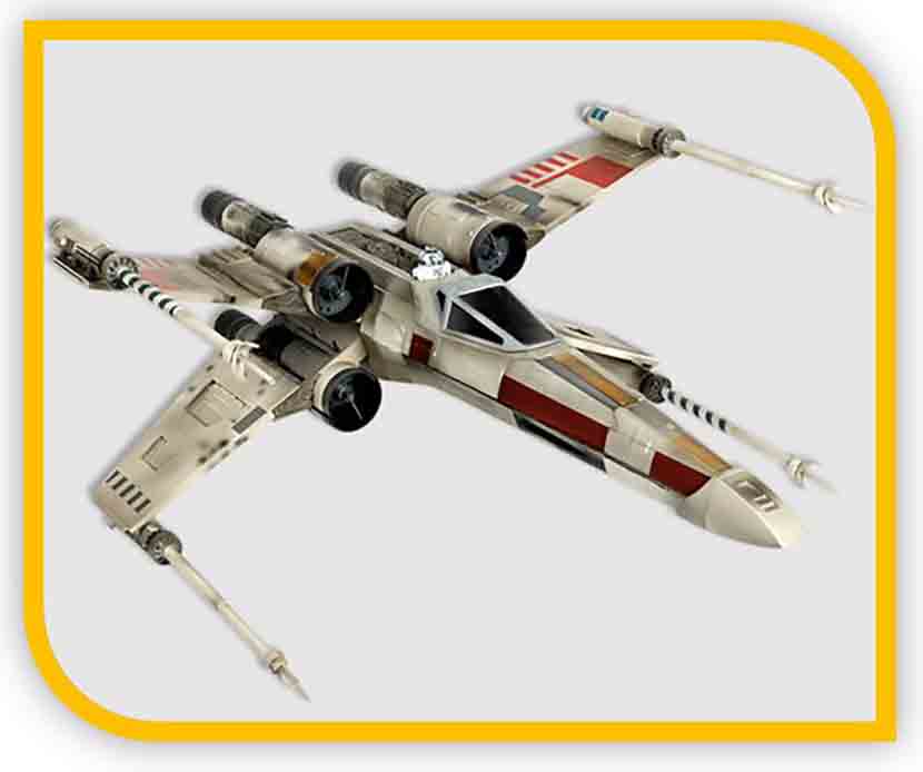
This week I was very funny, I had not worked with parametric design with laser cutting for a long time and I was able to have a little fun making an X-Wing model. My other parametric design is something more serious.
Then I started thinking about a name and designing a logo for my project. In addition, with the design, textile vinyl and the vinyl cutter I was able to make a t-shirt and stickers.
I will use the t-shirt to motivate myself when working on the project and for the presentation of my final project.
FILES
Parametric FabWingParametric Kit 2
GiveMe Tonics Logo