WEEK 09
- 1.-Introduction
- 2.-Teamwork
- 3.-Methodology
- 4.-Design of the parts
- 5.-Electronics
- 6.-Programming, firmware and software
- 7.-Updates
- 8.-Experience and conclusions of the week9
Mechanical Design, Machine Design:
Teamwork
Individual Assessment
Fab-Weeks
Are you looking for my assignments?
Links and notes
more information:
Week 09: Mechanical Design, Machine Design:
1.-Introduction:
This week is aimed at teamwork for the design and manufacture of a machine that can work automatically.

Curiosity:
The logo makes a little "joke" between the word "strawberry" and the "milling bit", which in Spanish are called the same, "strawberry", like fruit.
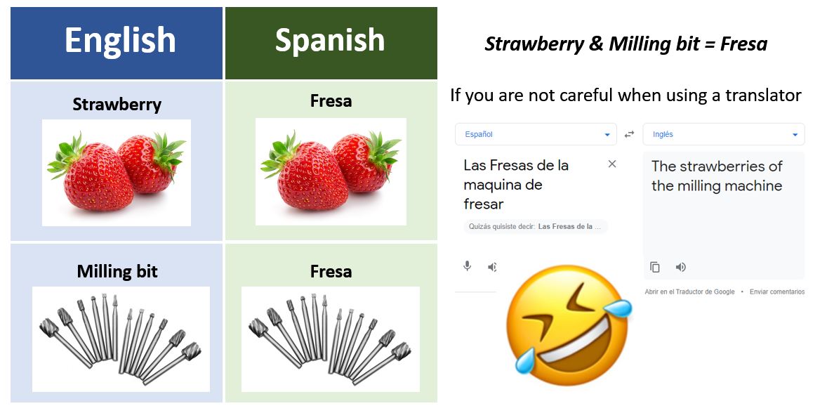
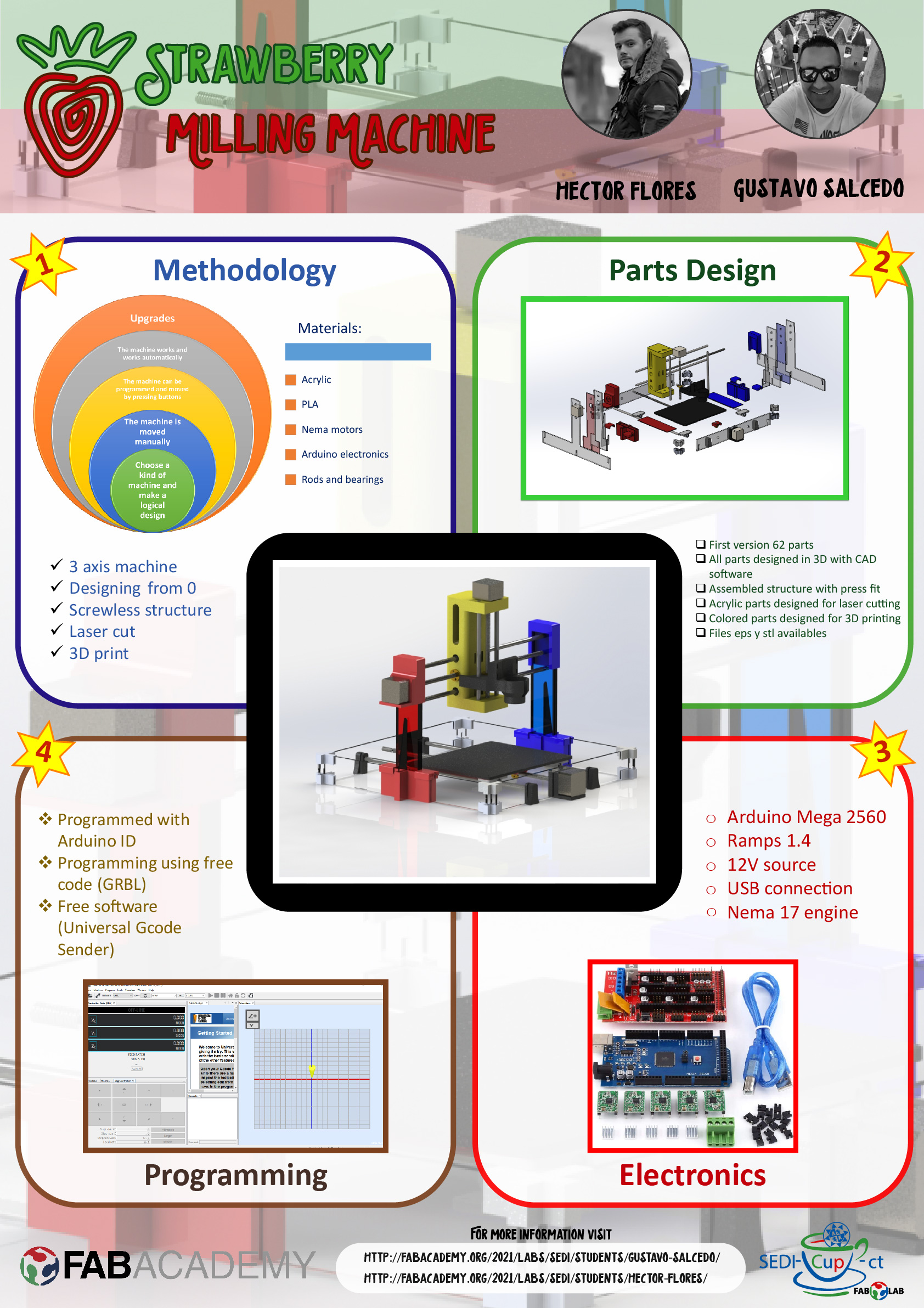
In our case we have created the Strawberry Milling Machine. A CNC machine for small milling jobs that can be built with acrylic material (made by laser cutting) and PLA thermoplastic parts (made by 3D printing).
It is designed to have the minimum number of screws possible, they are only used to anchor the motors and anchor the threaded rod coupling. In general, all of its parts are adjusted by press fit. If any user wants to manufacture his Strawberry Milling Machine, he has to take into account his press fit parameters, with his machines.
2.-Teamwork
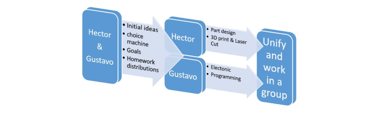
We have distributed tasks. Although we have both been present throughout the development, each one has focused on a few tasks to work in parallel and save time.
The general distribution of work can be summarized in the following scheme:
If you want to know the group assessment of this week, click on the image of SediCupCt.

3.-Methodology
The flow of the work methodology has been as follows:
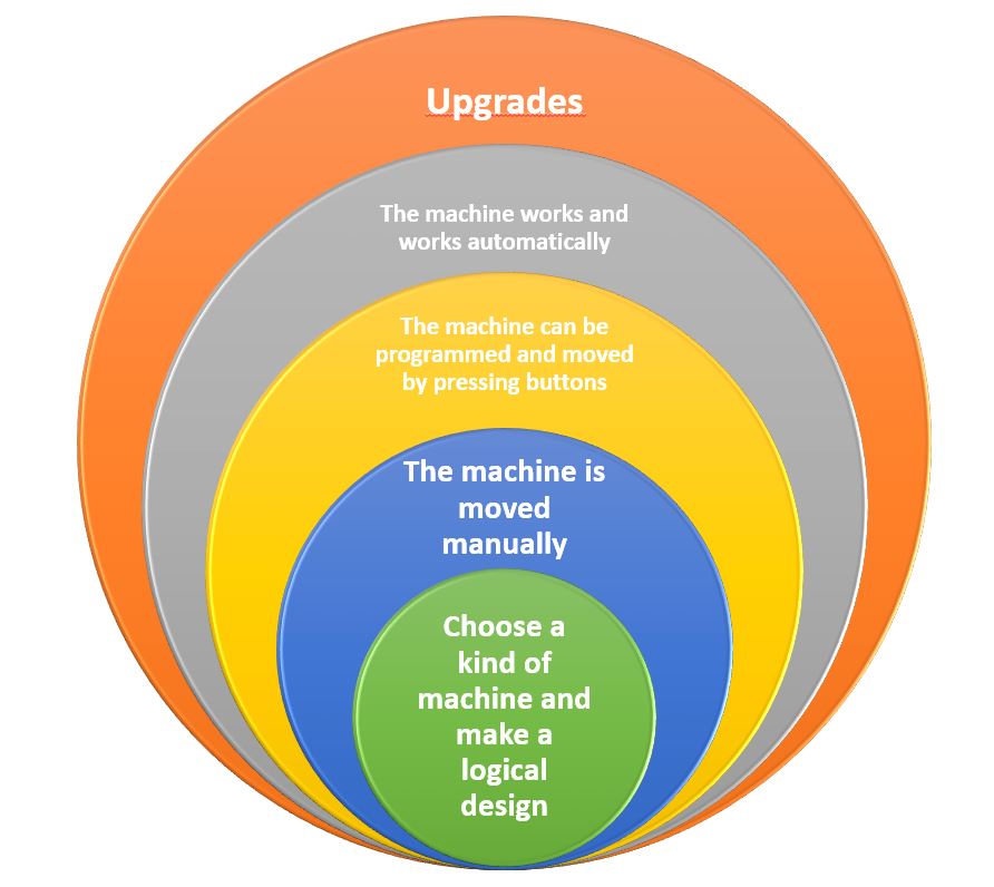
First of all, we have chosen the type of machine that we want to design and manufacture and we have established a scheme of 5 spirals, to mark the objectives of the machine.
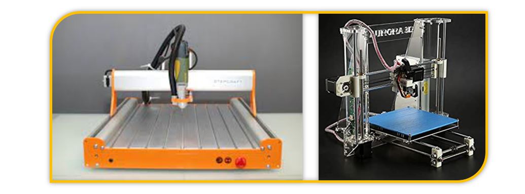
With the objectives, we have started to make some first sketches and ideas, to identify the shape of our machine and the possible materials to use.
Inspiration machines
We have distributed tasks. Although we have both been present throughout the development, each one has focused on a few tasks to work in parallel and save time.
Through the use of Solidworks the parts of the machine have been developed. All parts have been designed from scratch. The advantage of designing all the pieces is the possibility of knowing all their dimensions and being able to carry out an assembly to check how they work (digitally).
One possible downside is the redesign of some of the function parts being verified, as they were not functional or did not fit properly. At the same time you have to think about how to assemble it so that it is not difficult and the pieces have free space for assembly.
Parallel to the design of the parts, the Arduino programming and the operation of the motors have been worked to verify that they communicate by USB and work correctly.
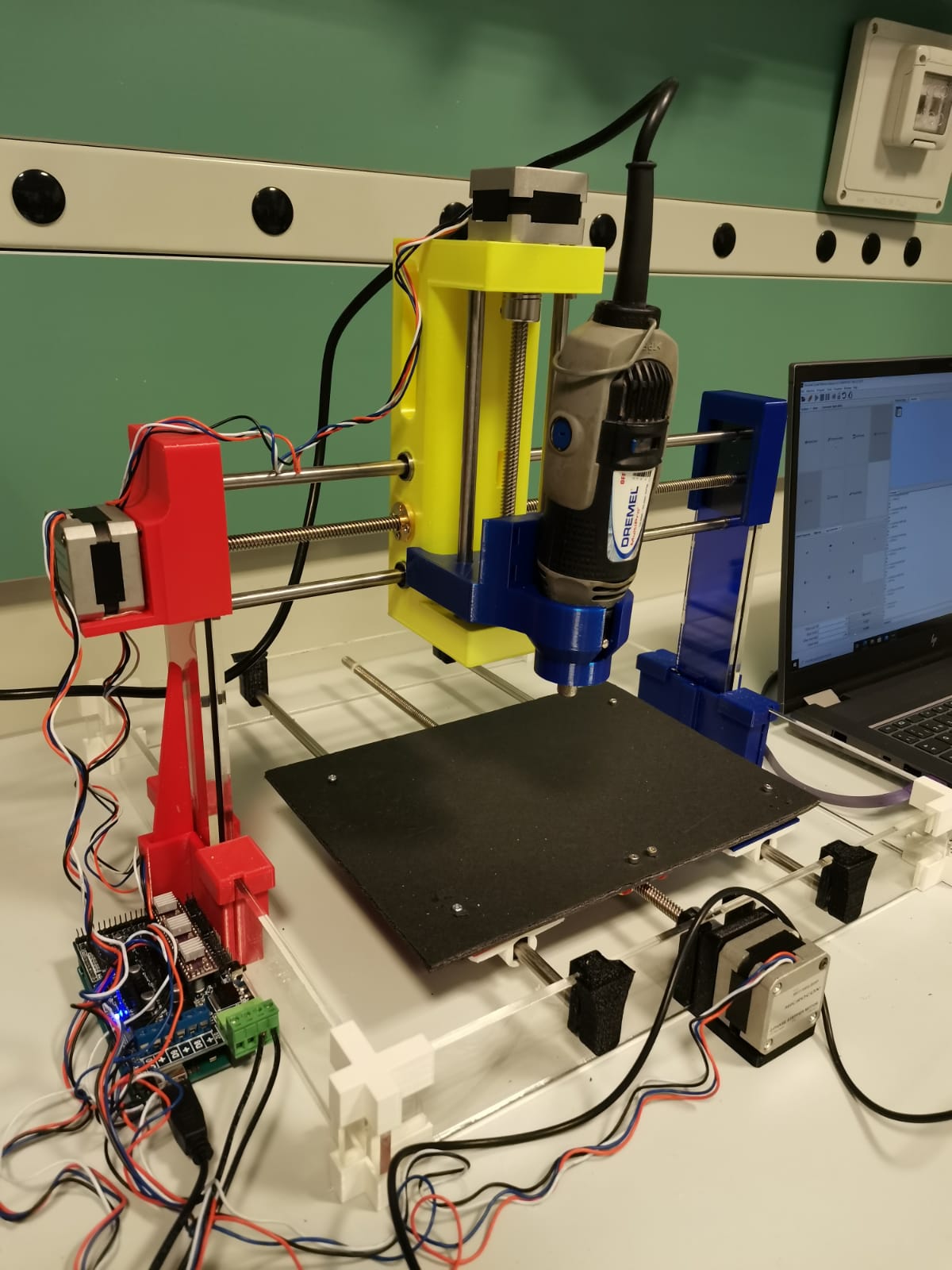
Finally, the Strawberry Milling Machine has been assembled, tested manually and with computer controlled movement before testing the automatic working mode.
4.-Design of the parts
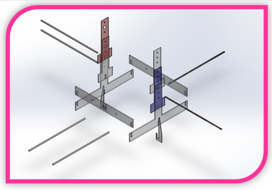
The first steps in the design have been the creation of the main structure of the milling machine.
They are designed for acrylic material, laser cut and press fit. They do not need screws. The use of glue is optional; we have not used glue.
The pieces are 5mm acrylic and the two colored pieces are 3mm acrylic.
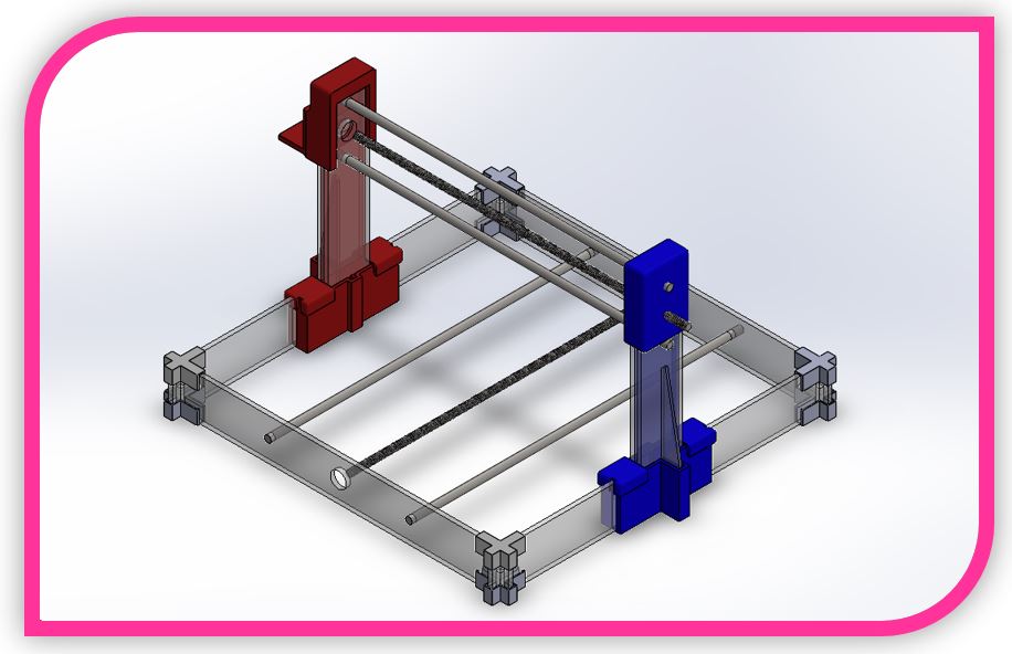
Placement of the acrylic structure and the rods.
Assembly of the acrylic structure and the rods.
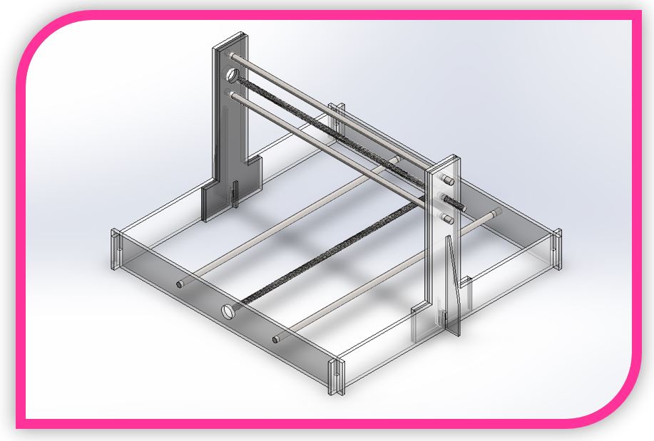
Two 8mm diameter rods are needed to cut to size, when coupled to motors. Also 4 non-threaded rods to favour linear movement.
Although the adjustment is by press fit, to reinforce stability, press fit reinforcement pieces have been created to aid the structure.
Reinforcement pieces.
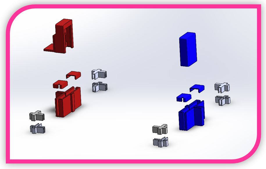
Assembling the reinforcements.

Visualization of the assembled reinforcements.
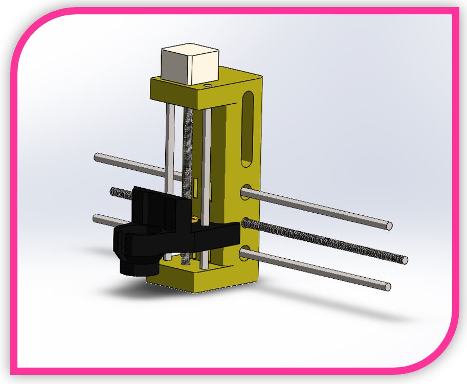
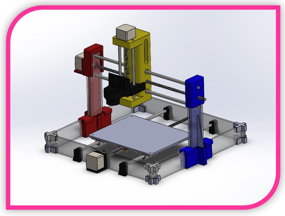
The carriage has the main body (yellow part) made in 3D printing. Likewise, the support part of the tool is also thermoplastic, by means of 3D printing.
Alignment of the carriage parts.

Assembling the carriage.
Exploded view of the work table, for milling.
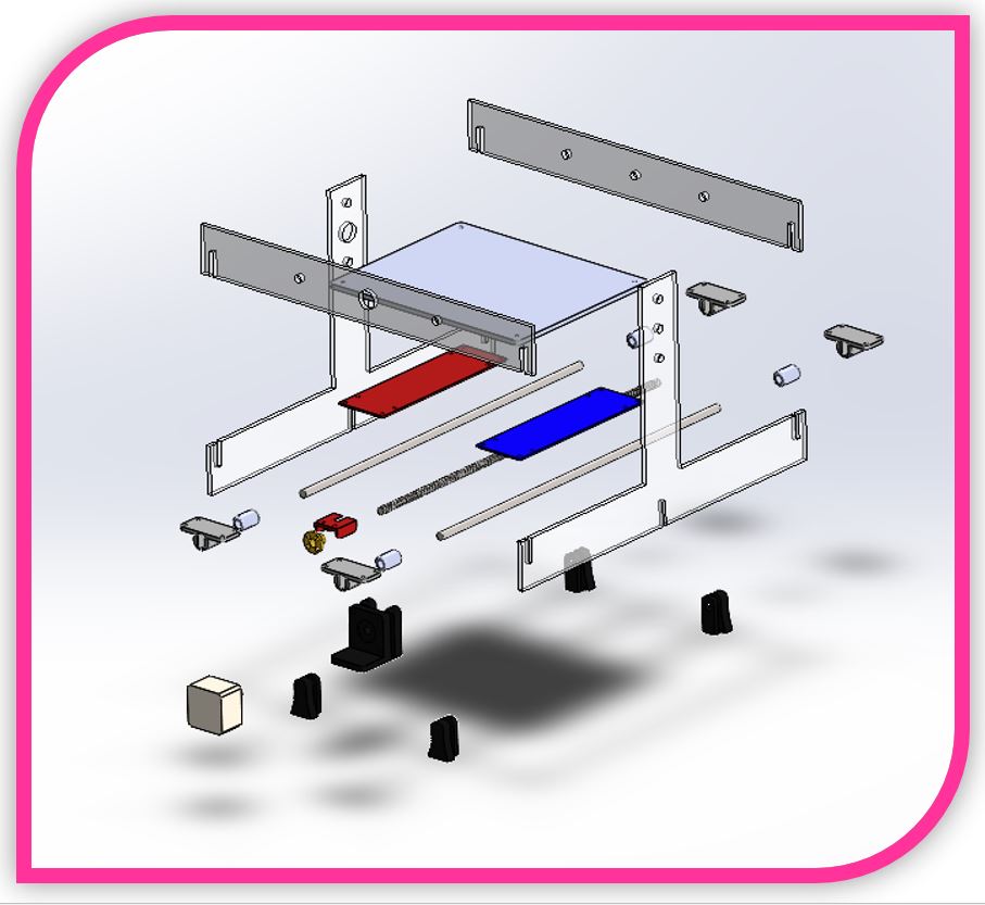
Assembling the worktable.
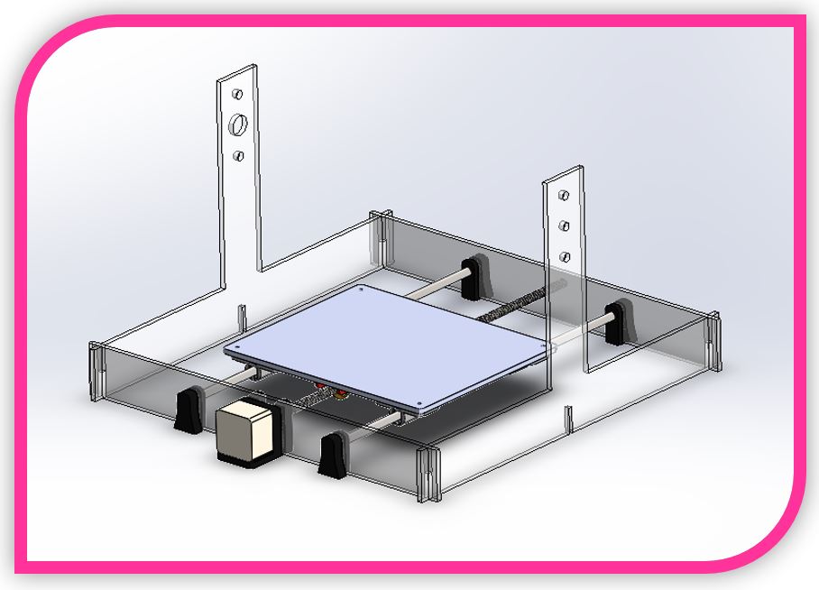
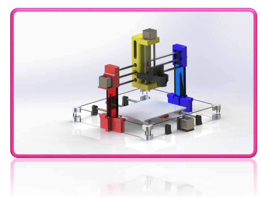
Strawberry Milling Machine Assembly.
Render of Strawberry milling machine. To have a first look at the finish of the machine.
5.-Electronics
For the electronics of the Strawberry milling machine you need:
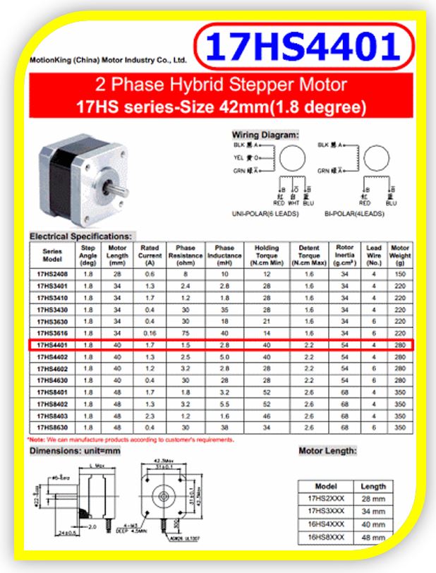
■ 3 nema 17 motors
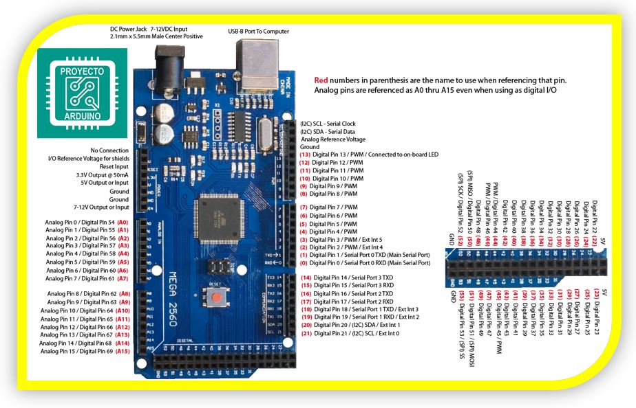
■ An Arduino Mega 2560 board
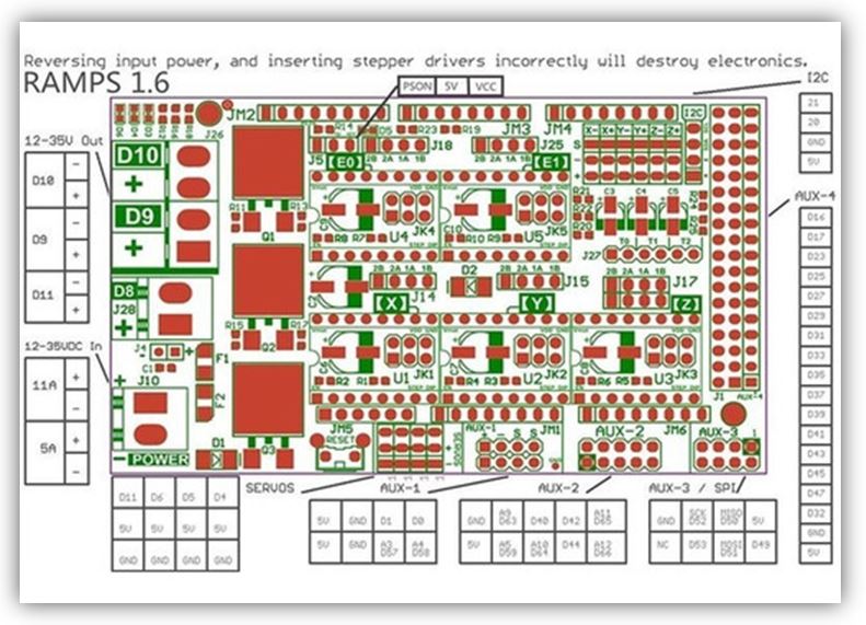
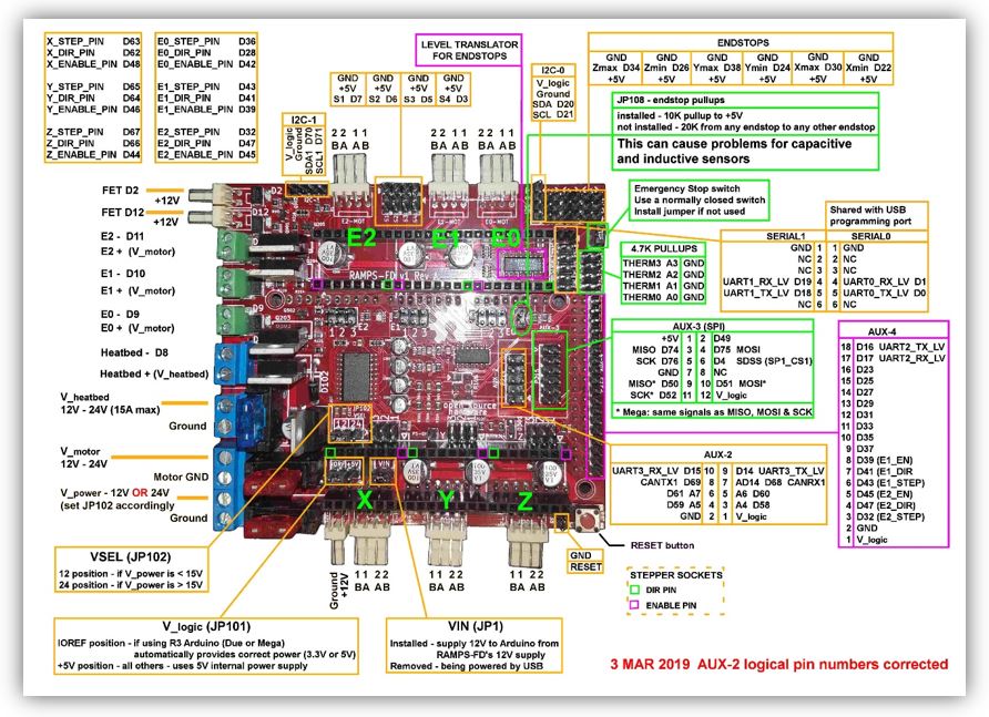
■ A Ramps 1.4 or 1.6 board
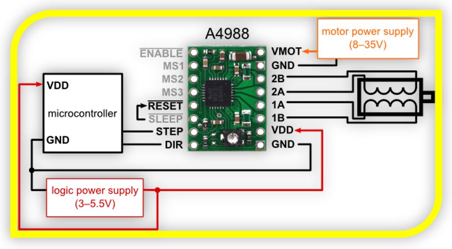
■ Drivers A4988
■ 1 USB cable (A to B)
■ A 12V Source
Datasheet for Arduino Mega 2560 board connections.
Datasheet for Ramps 1.6 board connections.
Datasheet for Ramps 1.4 board connections.
Datasheet for driver connections A4988.
6.-Programming, firmware and software
The process to work milling with the Strawberry milling machine is to choose the image or design that we want to mill and work it in Inkscape, to generate a vector file.
The image, we have to draw it in vector, in this case Inkscape is used to save the image in .ngc, which is the format understood by cnc through the Universal Gcode Sender software (this is a serial termination to communicate with the arduino and can make variations on the GRBL, which is the firmware that controls the machine). With the image created, it is loaded with the Universal Gcode Sender, configured and launched into the router bit, via a USB serial connection.
In order for it to work this way, the strawberry mill must first be programmed correctly, via firmware. To do this, the following sequence is followed.
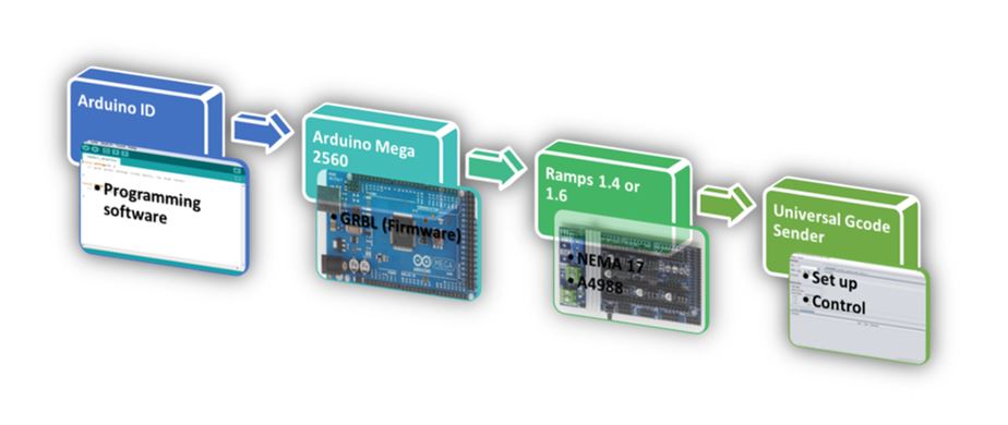
PROGRAM THE GRBL FIRMWARE WITH ARDUINO ID
** Never connect the CNC Shield without having previously loaded the GRBL since it can burn, especially if the arduino has another program previously.
** Universal Gcode Sender - It is shared development software; it can be found on GitHub.
** GRBL Firmware - This is also a shared use firmware; it can be found on GitHub.
Steps:
1. We connect the Arduino ID (free on the Arduino page, on any platform).
2. In the Program Menu -> Include .ZIP library -> add the path of the GRBL library.
3. After File -> Examples -> find GRBL -> open the example there is. Basically what it does is copy the library on our Arduino. It comes prepared for Arduino Uno and Mega 2560. We upload it, it may take a little while because it is a bit heavy.
4. Now, what is needed is to configure it, for this we need a serial monitor, which we can open from the Arduino ID. We open the monitor and set the serial port speed to 9600 bauds. It should show: (for the GRBL 0.8 verified with Arduino ID 1.6.7).
5. With the $ sign you can get help. We introduce $$ to generally configure the firmware. To change values, for the monitor put: $ item number = desired value. For example: change the heat of item 9 to 200 (instead of the 25 that were already on). Press enter to verify.
6. With $$ I can check that it has been changed.
7. These 22 parameters can be configured with other types of monitors in a simpler way, such as the Universal Gcode Sender.
UNIVERSAL GCODE SENDER
1. Unzip the ZIP files.
2. Open the .jar file. (1.0.8 tested version)
3. With this console, you can create macros, you can control the machine directly, you can search for a file (such as a picture) and send it. To configure it, it is done from Commands.
4. Connect so that Commands can be activated. To do this, refresh the ports at a speed of 9600 baud. Select the COM that detects us. Select the GRLB firmware and open the port.
5. Now from commands, we can put $$, as with Arduino ID, and the GRBL configuration comes out. (the most important parameters in our case are those of the motors, x, y, z step / mm, steps to move one mm and that depend on the motor and the threaded rod, default feed, default seek). See in the manufacturer the degrees that each step takes, 360 between the degrees per step, and it gives us the steps of a complete turn, for the rod, see the mm that it travels per turn. If, for example, the (propeller) rod makes one turn in a distance of 8mm, it will be necessary to divide the steps for one turn of the motor, between these 8mm for the turn. In this way I will obtain the mm of displacement for my motor and my rod, this is set for the x, y, z step / mm. (with the one mm rods, it stays as is).
6. The parameter (step pulse, usec) with which we will indicate the pulse width that Arduino will recognize. (with 10 it works fine) ($ 3 = 10 (step pulse, usec).
7. Default feed is the speed with load, and the default seek speed when searching for some position. The two should be the same, or with a slightly less load. This must be seen according to the user; the manufacturer does not provide information.
8. If the motor vibrates or jumps, the speed is too high, the steps are wrong, or the pulse is wrong.
9. At a very high speed, steps may be lost so the milling result will be poor.
10. (step idle delay, msec) is the delay time, after placing an order. 15 usually works well.
11. (acceleration, mm / sec ^ 2) acceleration of the motors, depends on the motors being used. It is advisable to start from a value of 30 and go up progressively, in case you want to put more acceleration. (500 high speed motors).
12. The parameters (junction deviation, mm) (arc, mm / segment) (n arc correction, int) are used for plotting arcs and curves, with values of 0.050, 0.100 and 25 in this order, it works fine. Change if the curves do not work well, although they are valid for the layout of circuits.
13. (n-decimals, int) put it to 3 decimal places, so you gain a little more precision than with 2.
14. (report inches, bool) value 0 if we work in inches or set to 1 to work in mm.
15. (auto start, bool) if it is set to 0, the Arduino must be programmed to start, while with a value of 1 it starts automatically.
16. (invert step enable, bool) in case other drivers other than A4988 are used and it is necessary.
17. (hard limits, bool) useful when using limit switches to stop the machine when it reaches the limits. Enable 1. Since this way when giving auto-home, it will look for the limit switches. With a value of 0, the home must be found automatically.
7.-Updates
■ Strawberry Machine head shape update.
■ End of career to avoid collisions.
■ Use of the interchangeable head.
■ Manual levelling of the work table.
■ Automatic levelling of the work table.
■ Improvement of the reinforcement pillar in a single piece.
8.-Experience and conclusions of the week9
This week has been one of the hardest so far. Although little by little it gets along well as it is a group work, motivation and encouragement always increase.
I have learned a lot about everything we have done, and it is quite a challenge to make a machine from scratch. It may be that between two people it is something hard, but we have been able to with it.
The advantage is that when one was locked, the other helped to unlock.
We ended up happy with the result we achieved and having to present it to our teammates has given us extra motivation.
“What went wrong”: The work area of the milling machine will need an improvement to be able to adjust its height and level it better. In the end we had to screw in the stepper motors. But the rest of the structure fits by press fit.
“What went well”: The strength of the structure and the fit of the tool to the head.
“What will you do differently next time”: Use a system with structural profiles and bearings instead of using rods.