WEEK 06
- 1.-Introduction
- 2.-Teamwork
- 3.-Eagle
- 3.1-Electronic circuit milling
- 3.2-Board soldering
- 3.3-Programming the board
- 4.-Circuit simulation
- 5.-Files
- 6.-Experience and conclusions from WEEK6
Electronic Design
Teamwork
Individual Assessment
Fab-Weeks
Are you looking for my assignments?
Links and notes
more information:
Week 06: Electronic Design
1.-Introduction:
In this week's group assignment we have worked on how to measure with electronic measuring devices, mainly the multimeter and the oscilloscope.
For the individual task, I have drawn my first electronic board "Hello", with the Eagle software, I have milled and soldered it. I have finally programmed it with the Fab ISP from the previous week.
For additional work, I have been testing a couple of circuit simulation applications.
2.- Teamwork
If you want to know the group assessment of this week, click on the image of SediCupCt.

3.-Using Eagle:
For this practice I used Eagle software for circuit design.
“EAGLE is electronic design automation (EDA) software that lets printed circuit board (PCB) designers seamlessly connect schematic diagrams, component placement, PCB routing, and comprehensive library content.”
As a support point for routing tools, you can refer to the link:
Eagle Turorial
Download:
I downloaded the software for Windows.
After running the program. First I start with File New Project:
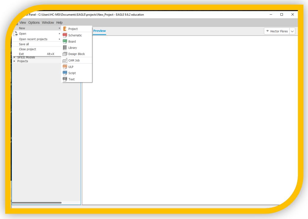
A new empty project will be created, inside the assigned project folder:
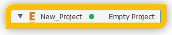
In the event that the circle shown in the image is gray, we must click on it to make it green, indicating to the program that we are going to create the following files there.
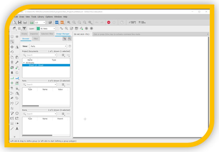
Now I am going to create the schematic, for this, file / new / schematic and the work window for the schematic will open.
If you do not have all the necessary components in Eagle, a good library of electronic components to start working with is the FabAcademy:
It can be obtained in the part corresponding to the resources for Eagle:
http://pub.fabcloud.io/tutorials/week06_electronic_design/eagle_resources.html
Or download from Git:
https://gitlab.fabcloud.org/pub/projects/blob/master/files/fab.lbr
Once downloaded, you just have to copy the file. lbr in Eagle's library folder. In my case, the default installation "Documents -> Eagle -> Libraries":
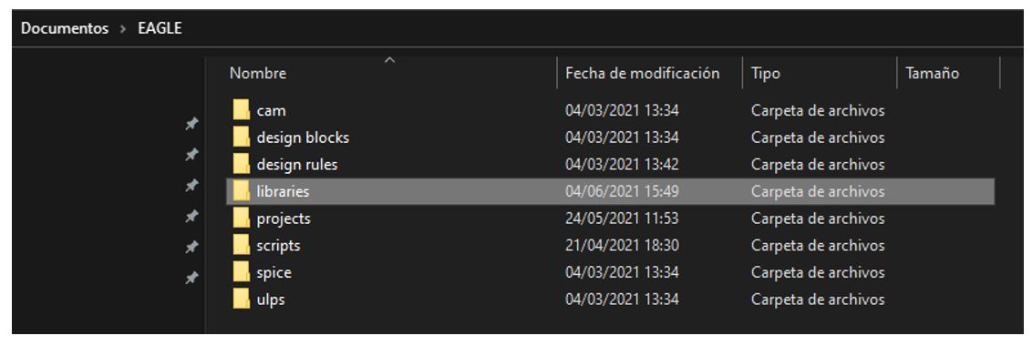
And inside this folder I am putting the libraries that I am going to use.

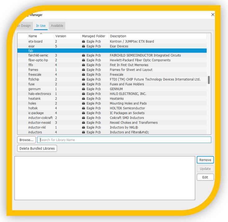
Once the library is installed, from Eagle's library manager I can add or remove it to use it in the project.
To add it, I can go to the “Available” tab of the library manager, select from the list and press “Use”.
If it does not appear in the list, click on “Browse…”, indicate the location of the folder with the library (libraries by default), select the desired library and click on open.

The first thing I'm going to do is load the fab library, from the library manager:
Then, from the add part button I can load components from my library:
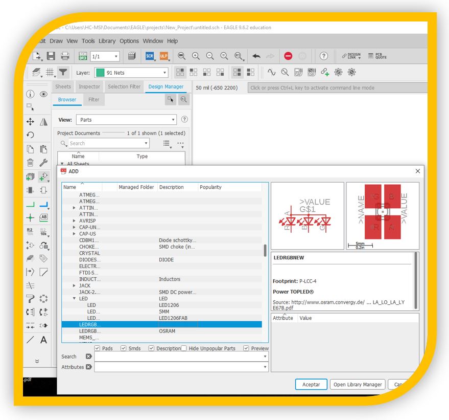
In the upper right I have its representation for the schematic (left) and its representation for the schematic of the board (right).
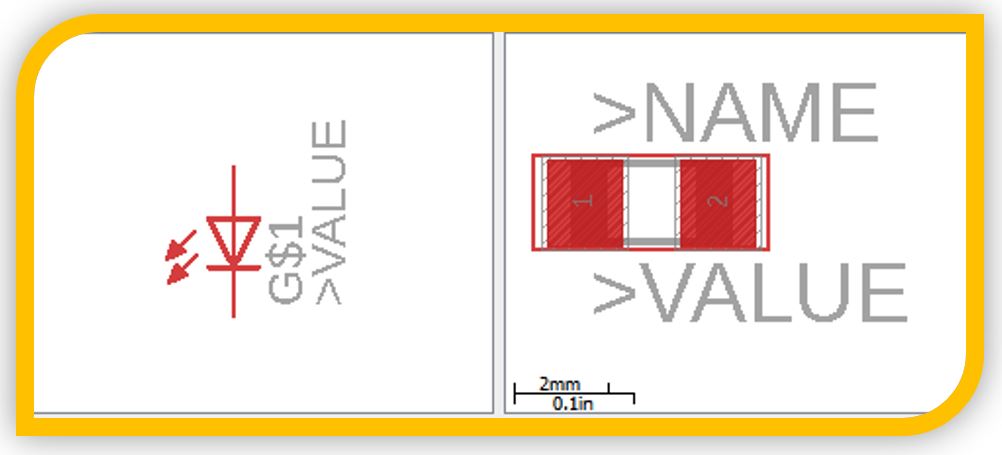
Pressing to accept, the mouse pointer will change to the drawing of the led and by clicking on the work area I will place it. I'm going to put up a resistor as well.
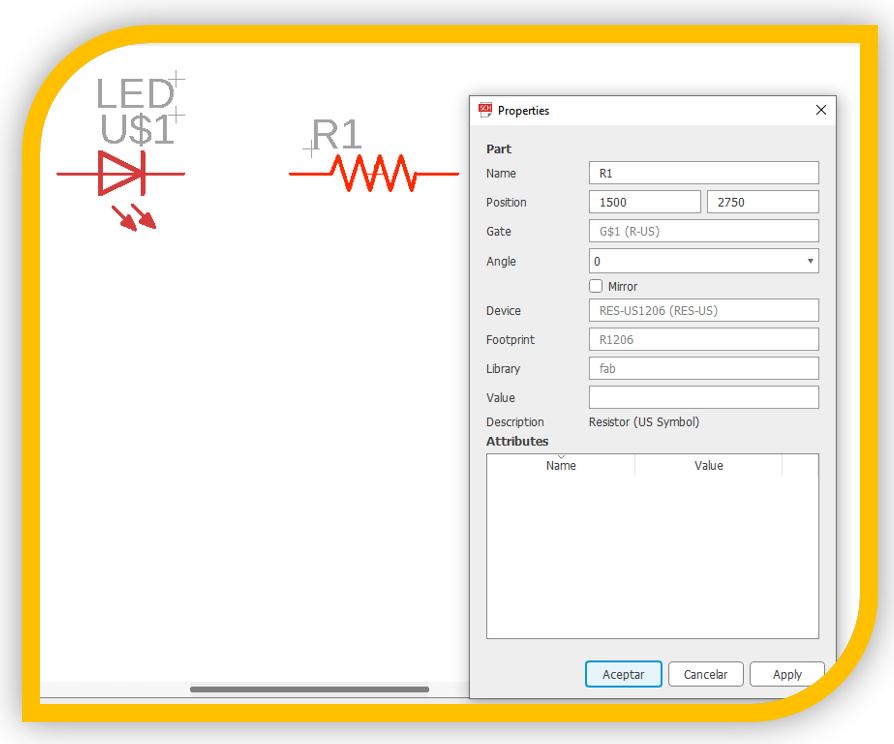
There I can put the values and the name.
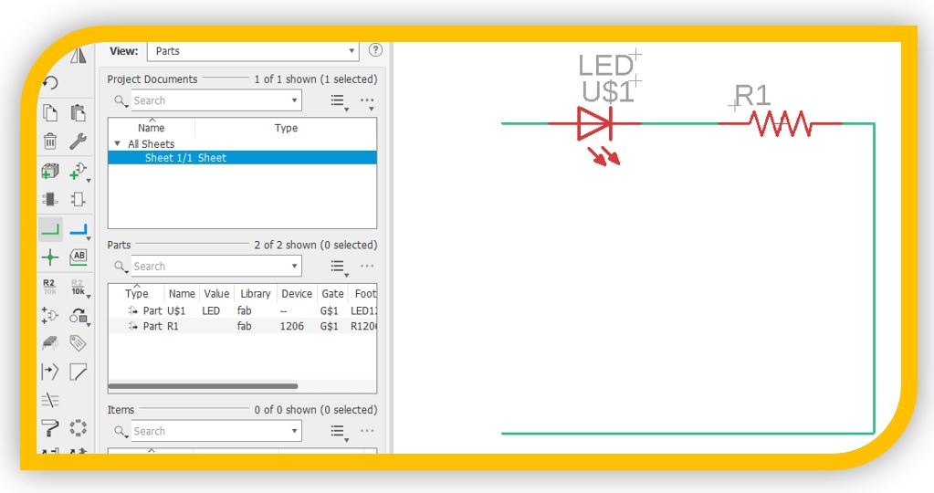
To join the components together, I can use the net tool (symbol "L" lying green).
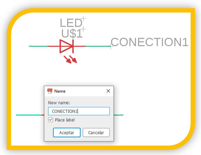
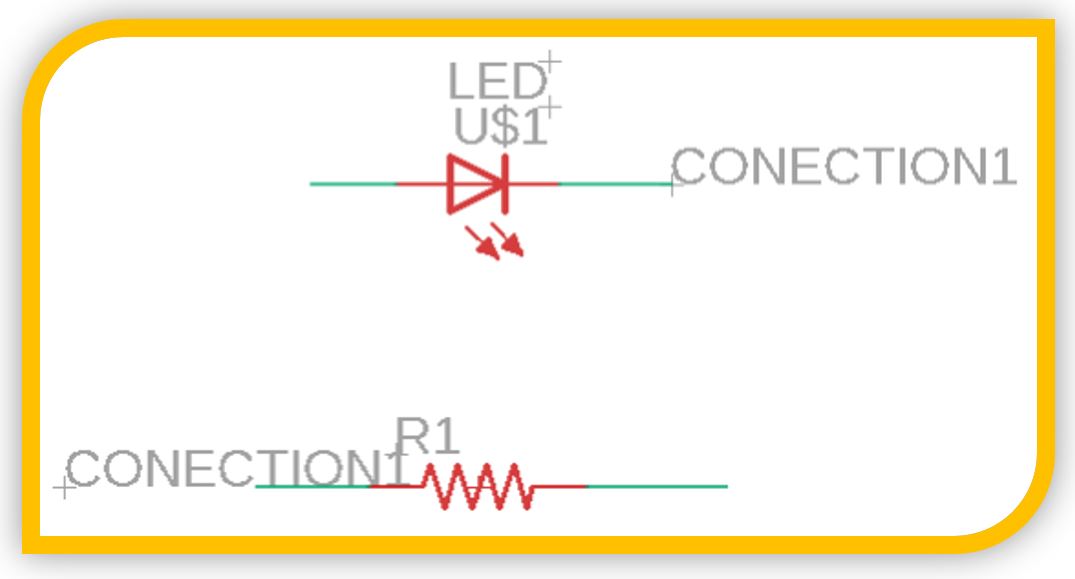
Or another option, is to put labels with names at the ends of the component, if the labels are called the same, they will be interconnected between them.
With these basic concepts, I am going to start drawing a schematic with the Atiny 44, with an LED to make the "Hello" board.
Fully designed schematic:
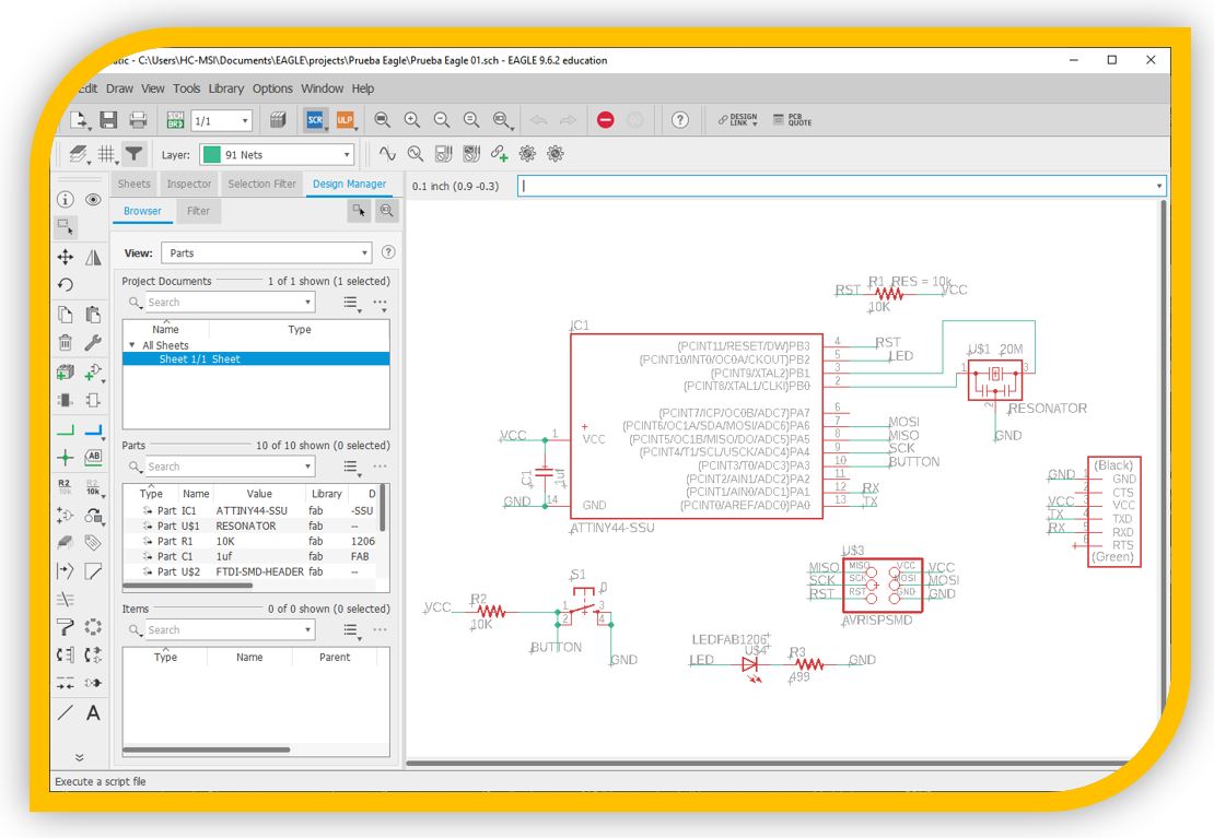
I have used both labels and net connections.
After completing the schematic, I run the command generate switch to board.

Now a new window will open with a black background that represents the board on which to put the components. The components of the schematic will appear in the lower left, displaced.
If the labels and the net were correctly placed, in the schematic drawing, the components will be connected by a yellow line that shows how the components are connected to each other.
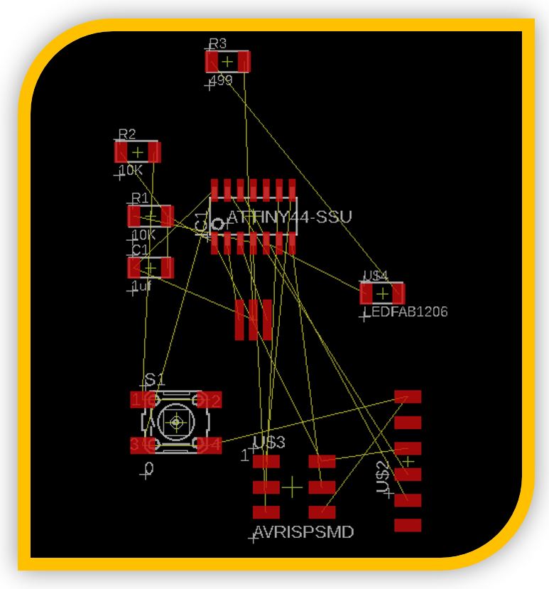
Those connections are what we will have to join by drawing the tracks of the circuit. For this we have two modes, automatic mode, autorouter and manual mode:
The Autorouter mode will join the components automatically, according to the configurations that we mark. For example, only in layer 1 top, with (effort) effort low and with 8 iterations.
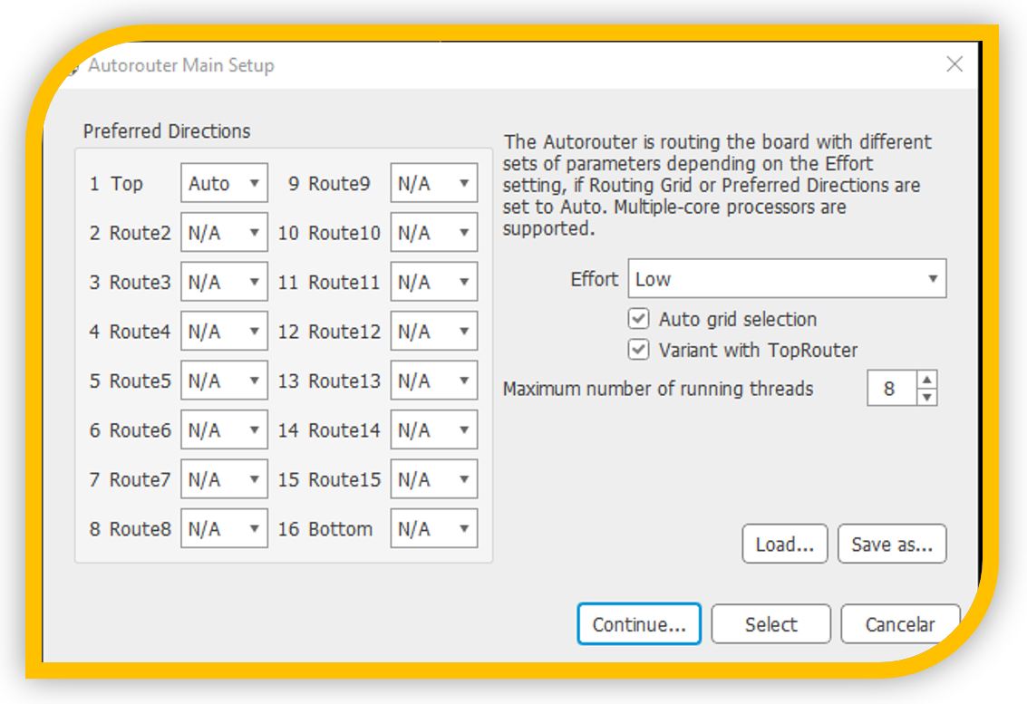
In this case, it shows me 5 routing variants:
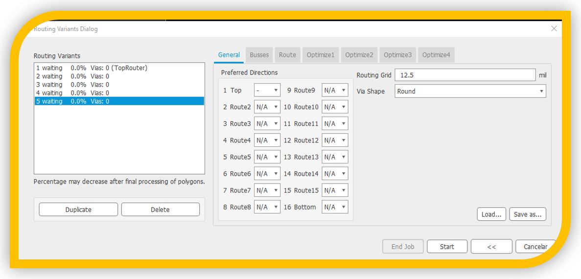
Each of them can be configured with its automatic routing parameters, and then, if start is pressed, the process will begin:
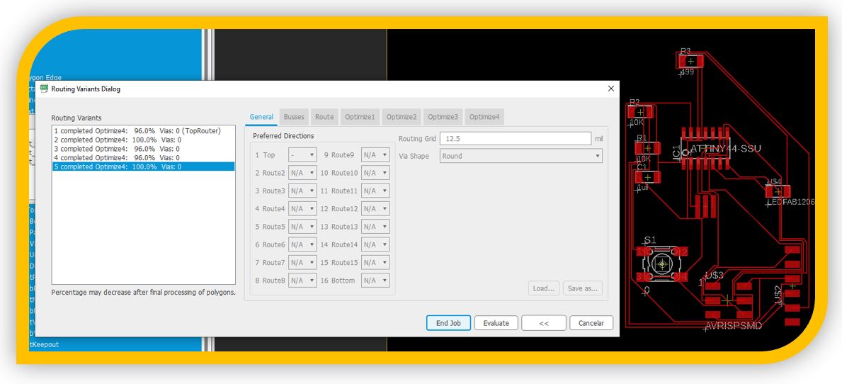
2 of 5 are 100%, I'm going to see option 2:
** I observe that, although this is good, the size of the tracks is very small for the milling machine and they may go wrong.
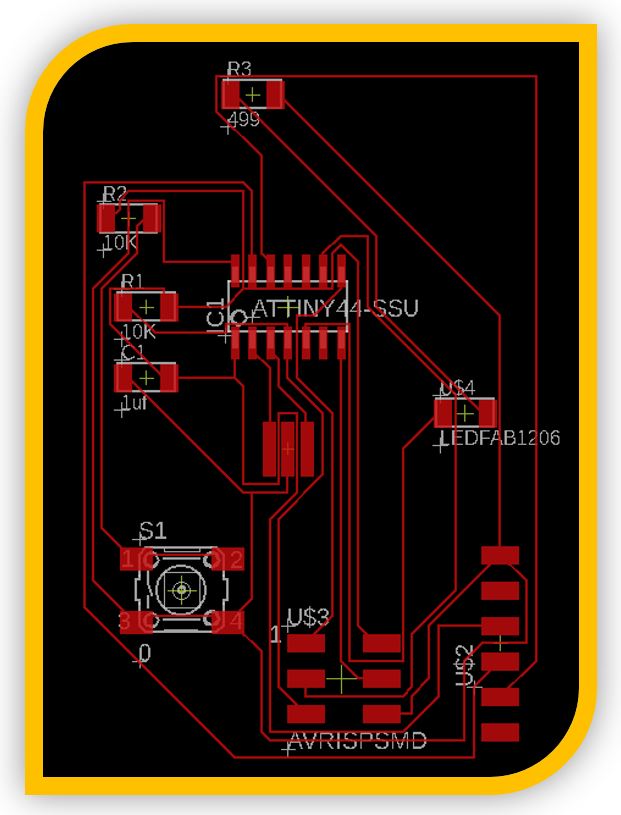
On the Dimension layer, you can modify the strokes and the shape for the plate, to create shapes other than a rectangle.
*** To avoid that the tracks of the tracks are too fine, I am going to load the settings recommended in the FabAcademy documentation for the size of the tracks. I can do this from the design rules window.

Besides, if necessary, the values can be modified as desired.

I redraw my plate with the new rules:

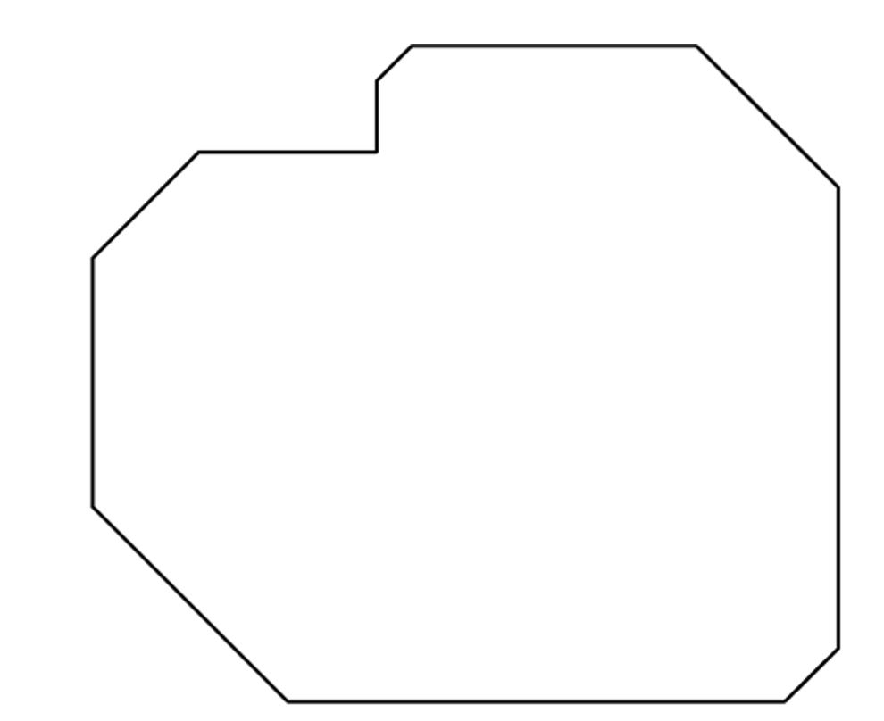
Confirmed the unions, I create my image in negative for the engraving of the tracks:

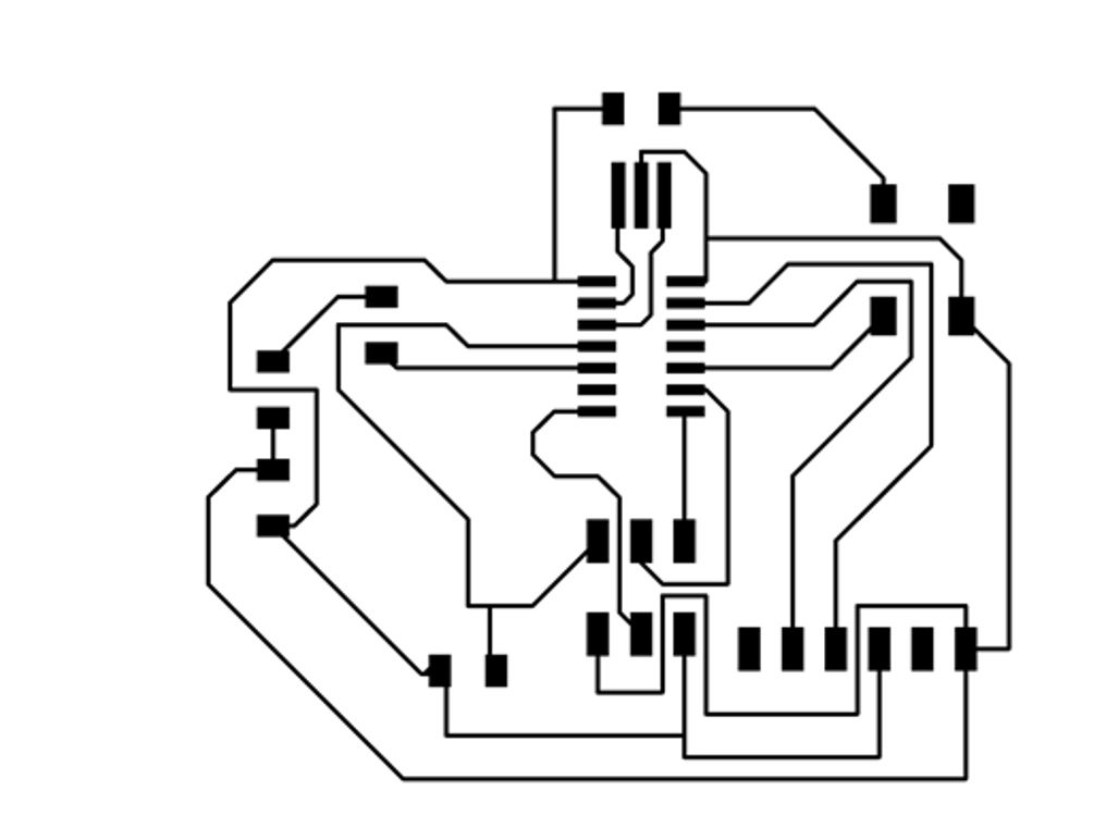
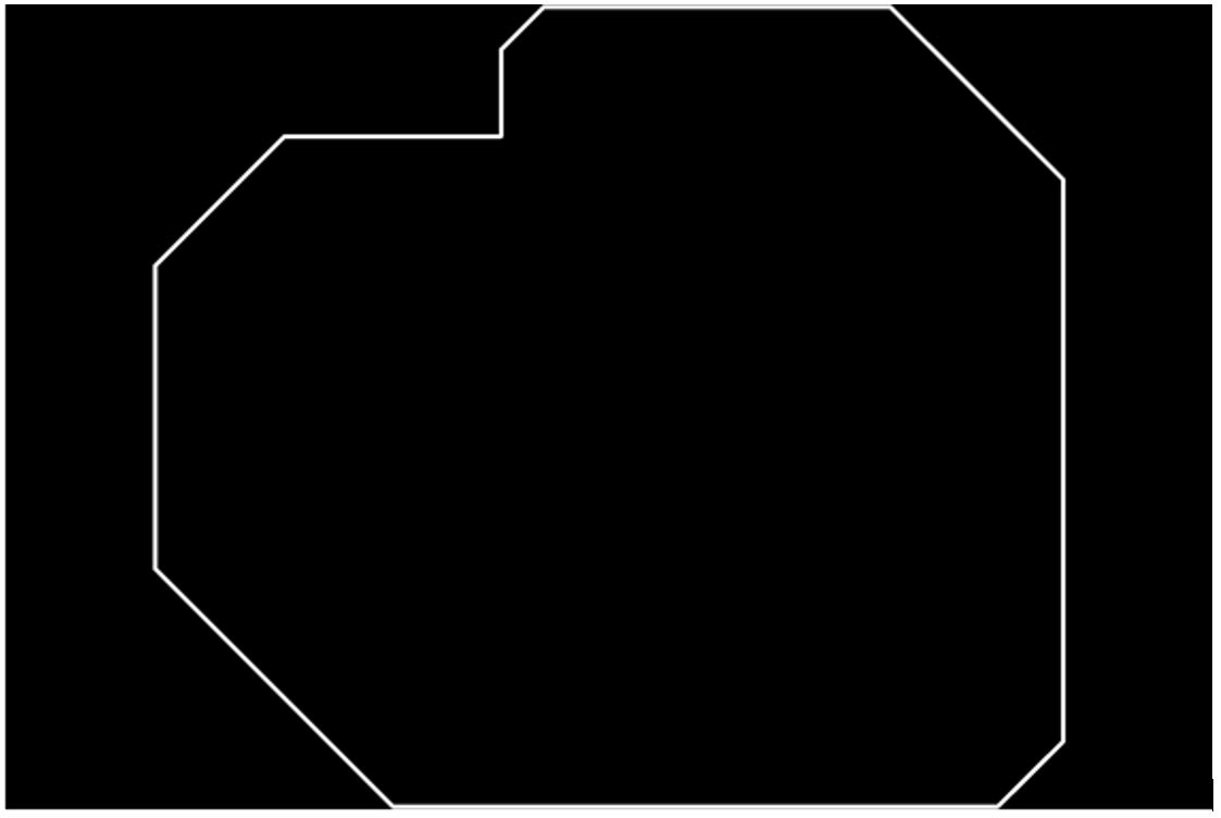
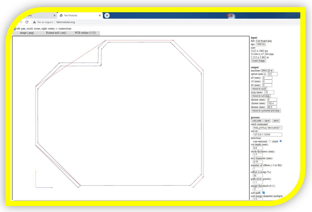
And my image for cutting the plate:
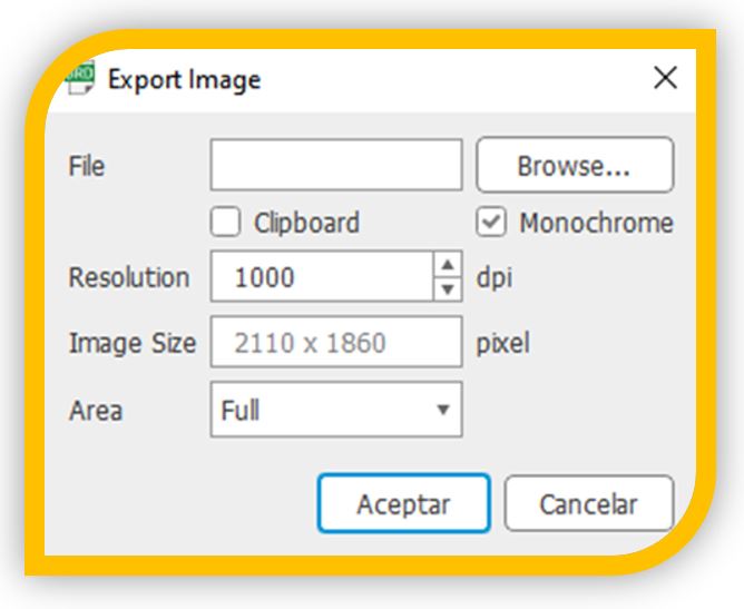
*** IMPORTANT NOTE: when exporting the image from Eagle, it must be specified that it be done in monochrome and at a resolution of 1000 dpi:
3.1-Electronic circuit milling:
I used the Fabmodule to generate the milling code. Upload the png of the circuit.
■ NOTE: I used fabmodule because my colleagues used it last year but now there is a much more advanced option than fabmodule and more advisable:
http://modsproject.org/ or http://mods.cba.mit.edu/
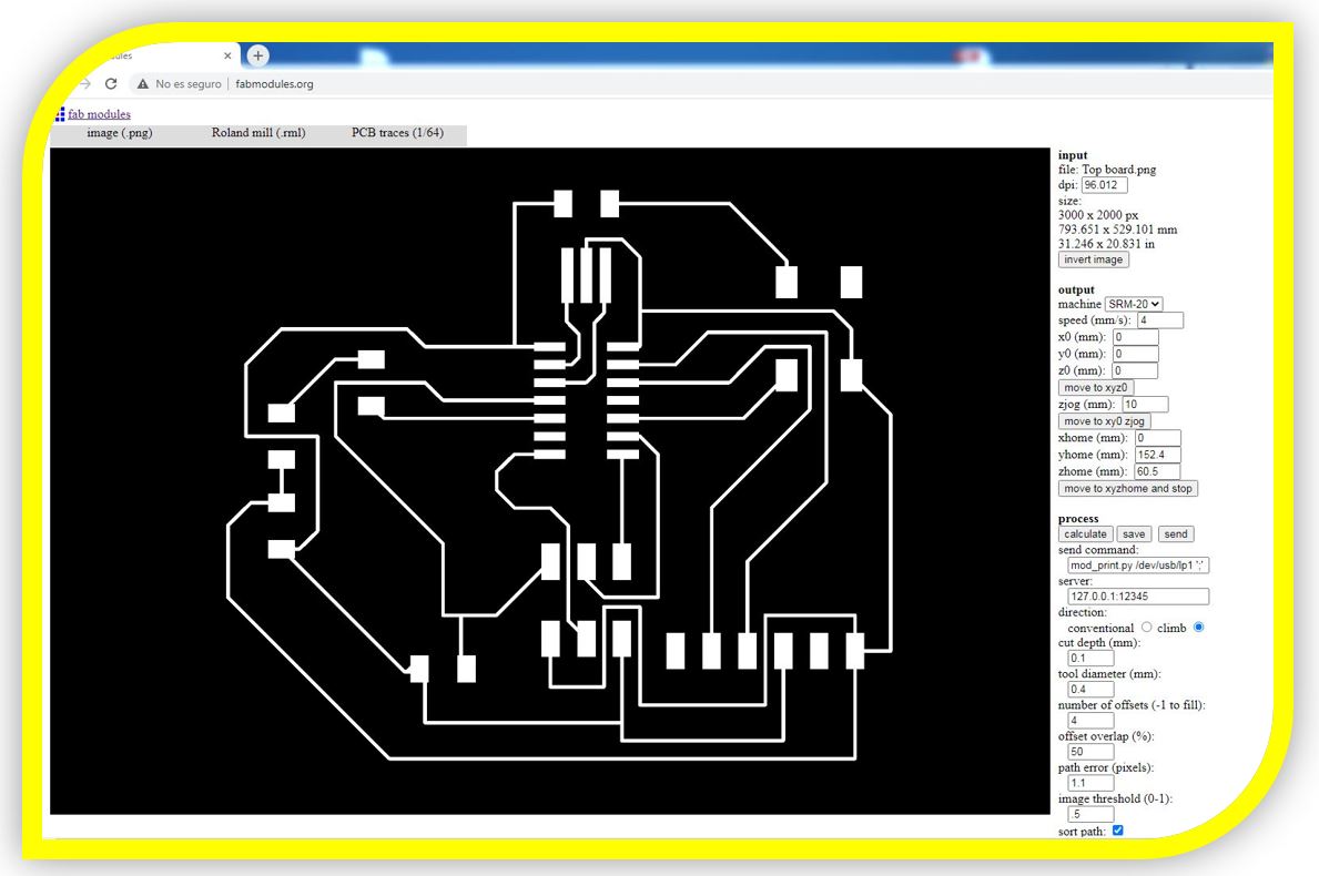
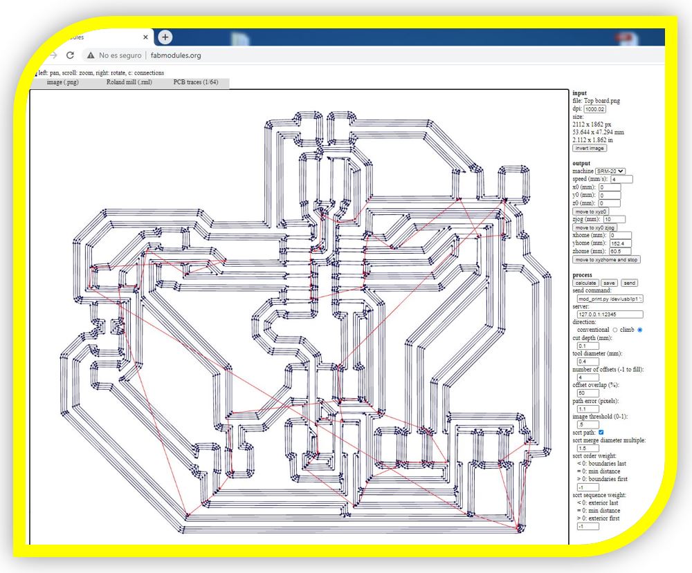
I configured the parameters and calculated to generate the code to send to the milling machine software
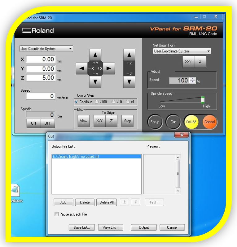
Export the codes to the mill control software, calibrate the 0 of the axes, and run
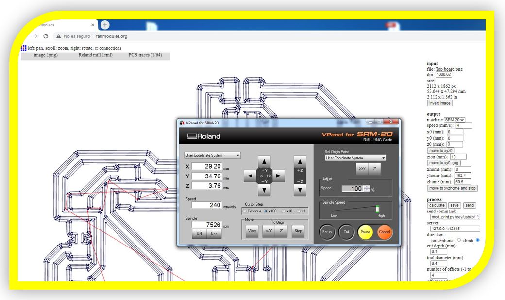
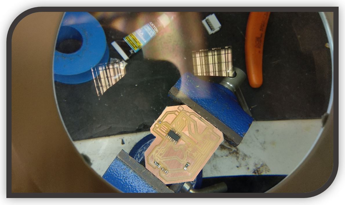
Top layer milling. With the mil of 0.4mm.
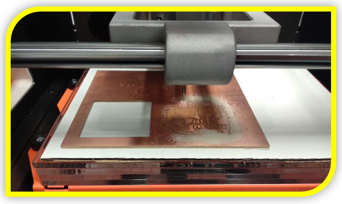
Board cutting with the 0.8mm mil.
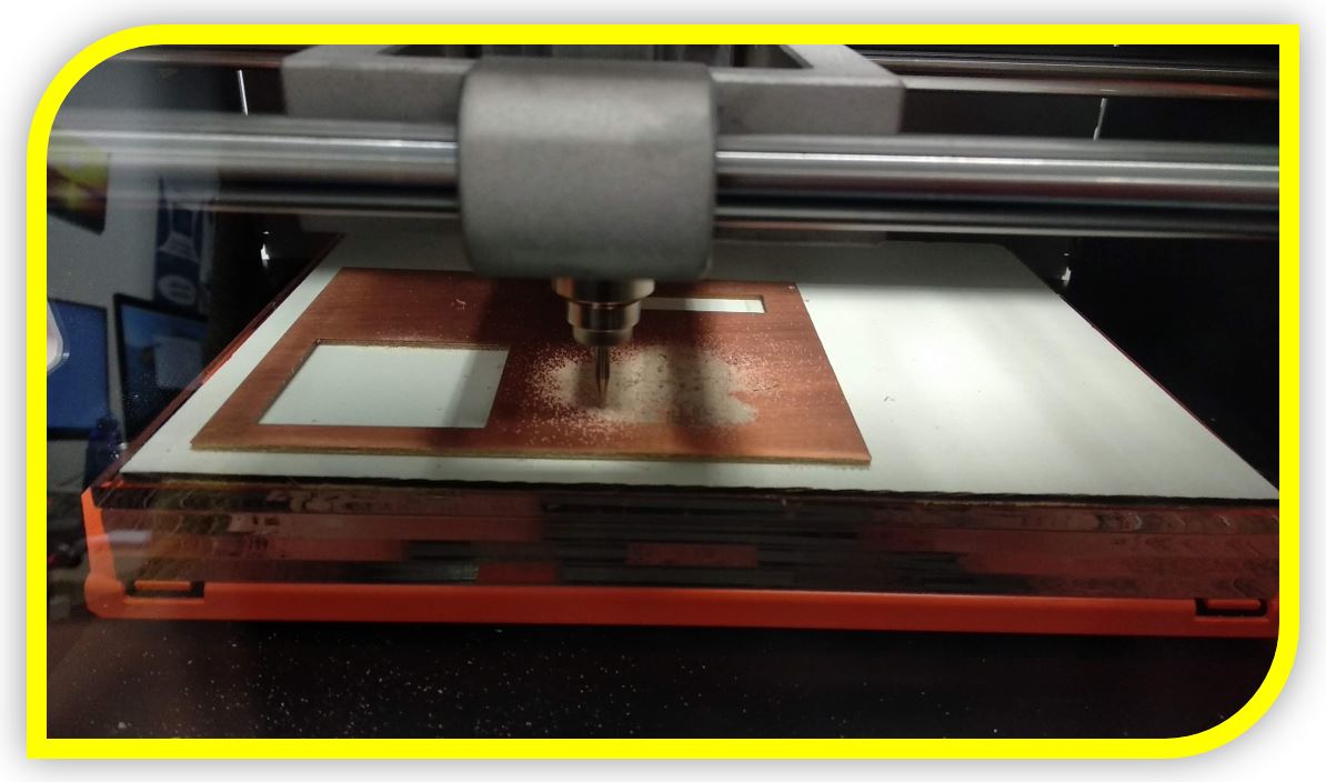
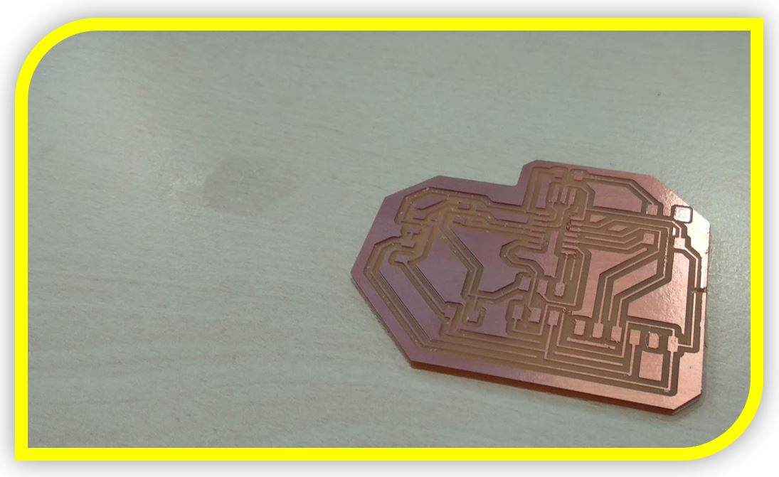
The result:
3.2-Board soldering:
To solder the components of the board, use a tin soldering iron, fine tin filament, an electronic magnifying glass, some tweezers to place the components and most impor tantly, flux for soldering.
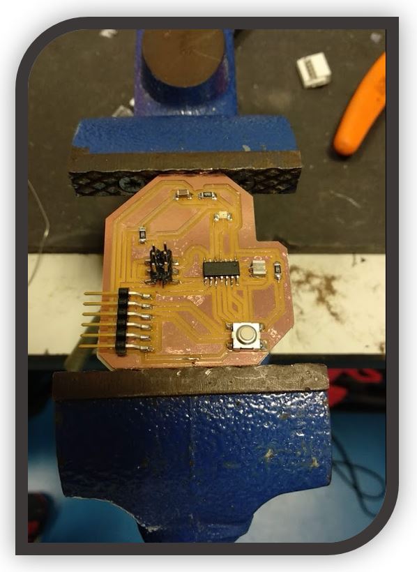
The components that I use are the following:
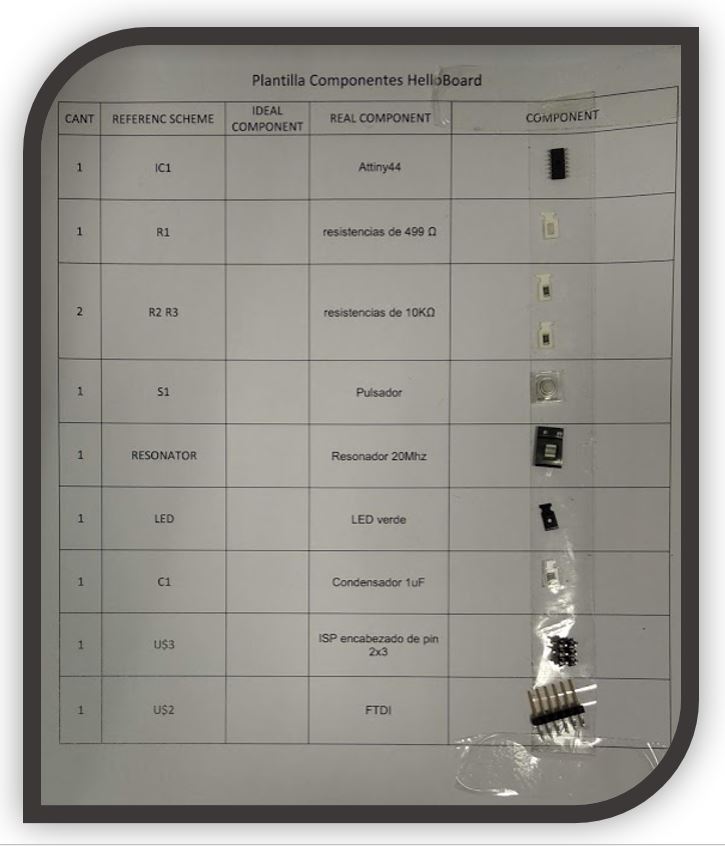
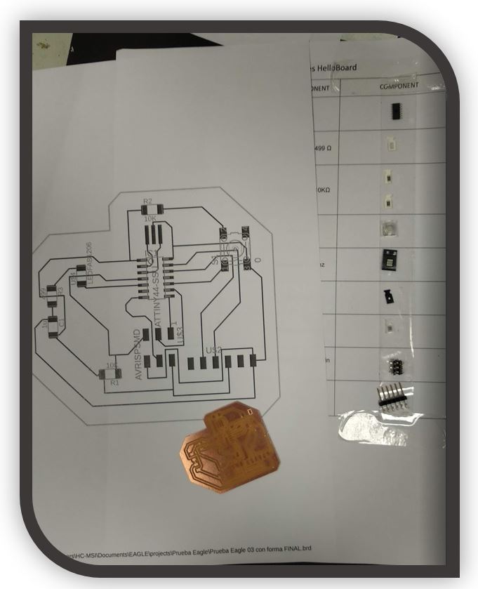
Placing the first components
All board welded
3.3-Programming the board:
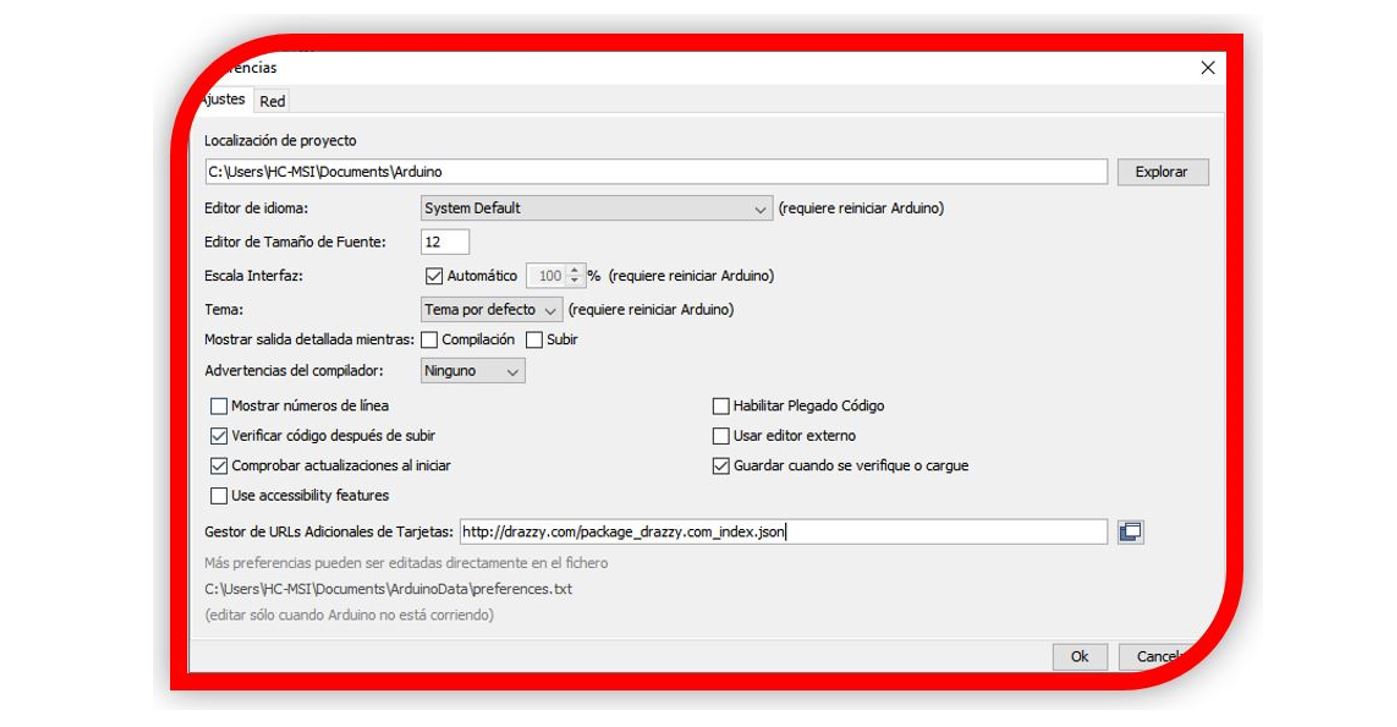
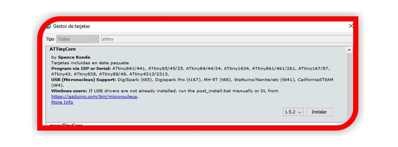
I install the libraries: https://github.com/SpenceKonde/ATTinyCore
I have to copy the following link, in the preferences window of Arduino ID. As seen in the image.
http://drazzy.com/package_drazzy.com_index.json
In the Tools window, I look for the Attiny boards and install them.
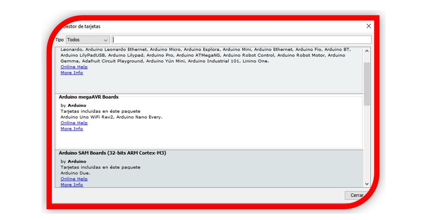
In this case:
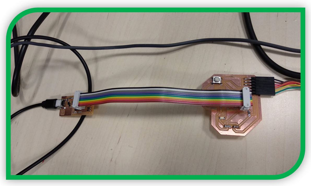
With the libraries already installed, I can now program the board.
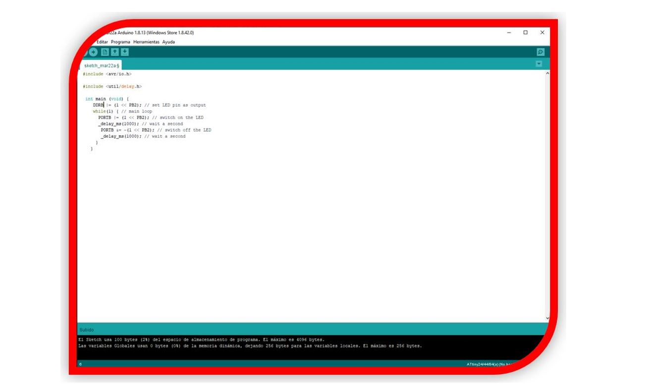
Then it is only to connect the electronic board to the programmer, as in the previous week, compile to verify and burn.
4.-Circuit simulation:
I tried two free options.
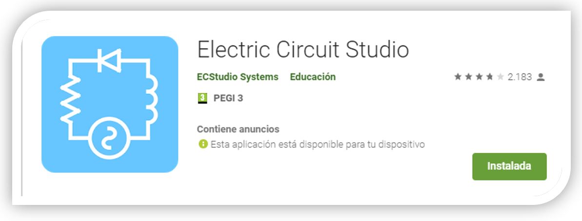
1. Electric Circuit Studio
It is an electrical circuit simulator, which I found by searching in Android apps.
https://play.google.com/store/apps/details?id=com.ecstudiosystems.electriccircuitstudio&gl=ES
The circuits and measurements can be worked from the mobile phone.
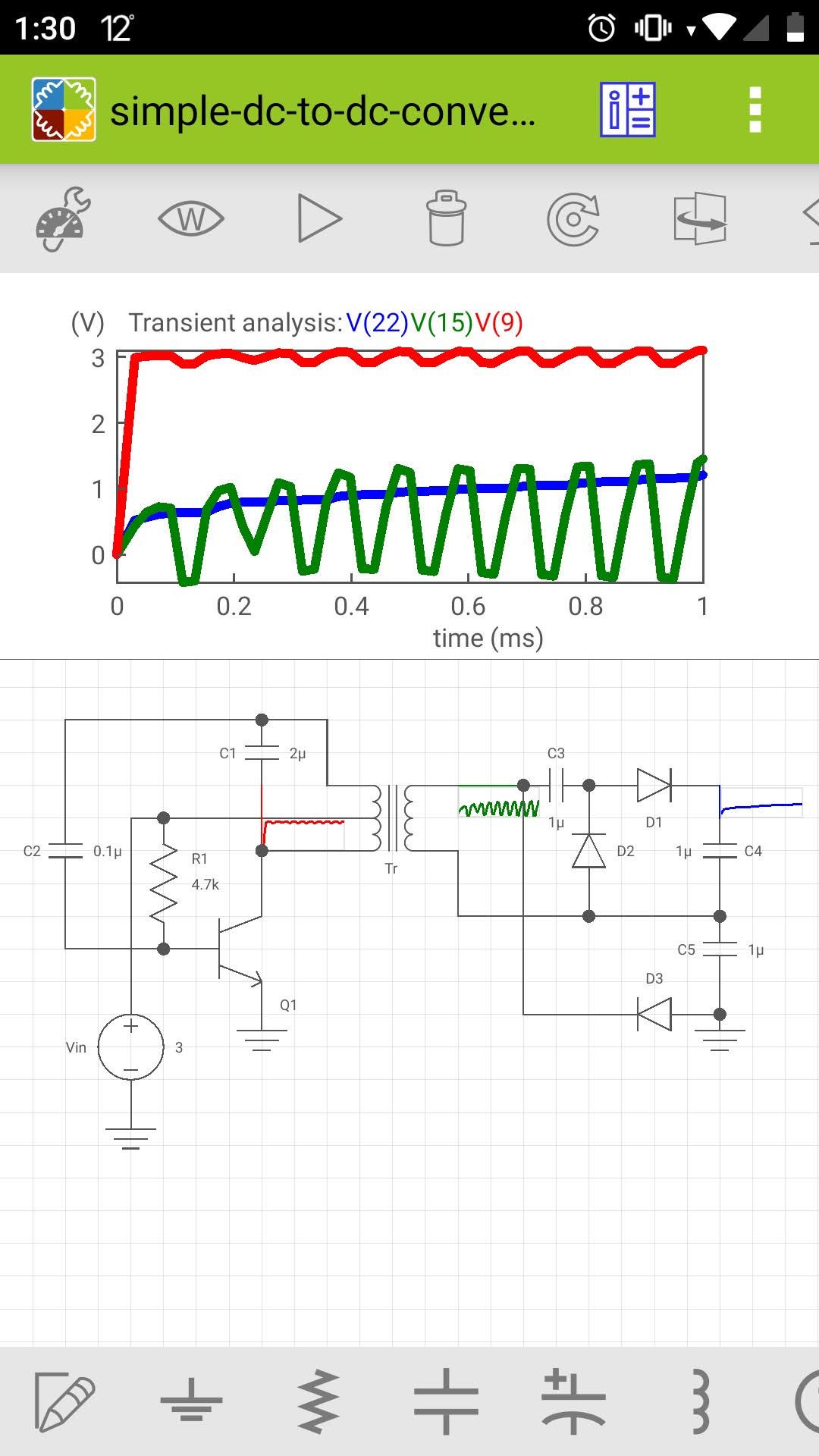
The first example I tried was that of a DC converter, an example created.
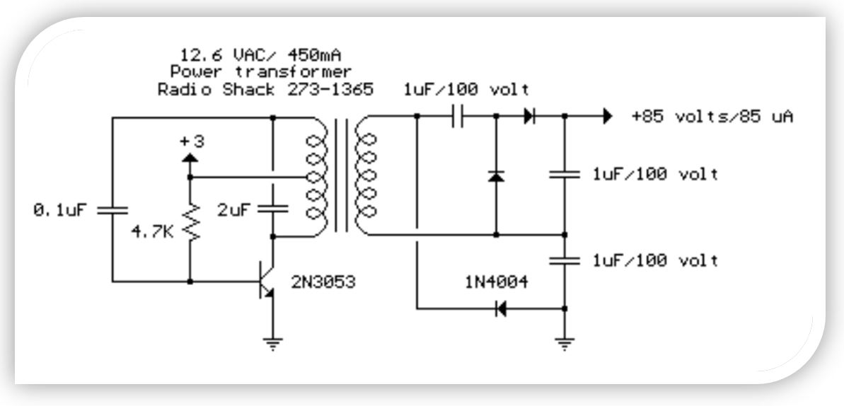
Simple DC to DC Converter:
The circuit below is a DC to DC converter using a standard 12 VAC center tapped power transformer wired as a blocking oscillator. The circuit is not very efficient but will produce a high voltage usable for low power applications. The input battery voltage is raised by a factor of 10 across the transformer and further raised by a voltage tripler consisting of three capacitors and diodes connected to the high voltage side of the transformer. The circuit draws about 40 milliamps and should operate for about 200 hours on a couple of 'D' alkaline batteries. Higher voltages can be obtained by reducing the 4.7K bias resistor. More information on blocking oscillators can be found here: Blocking Oscillators
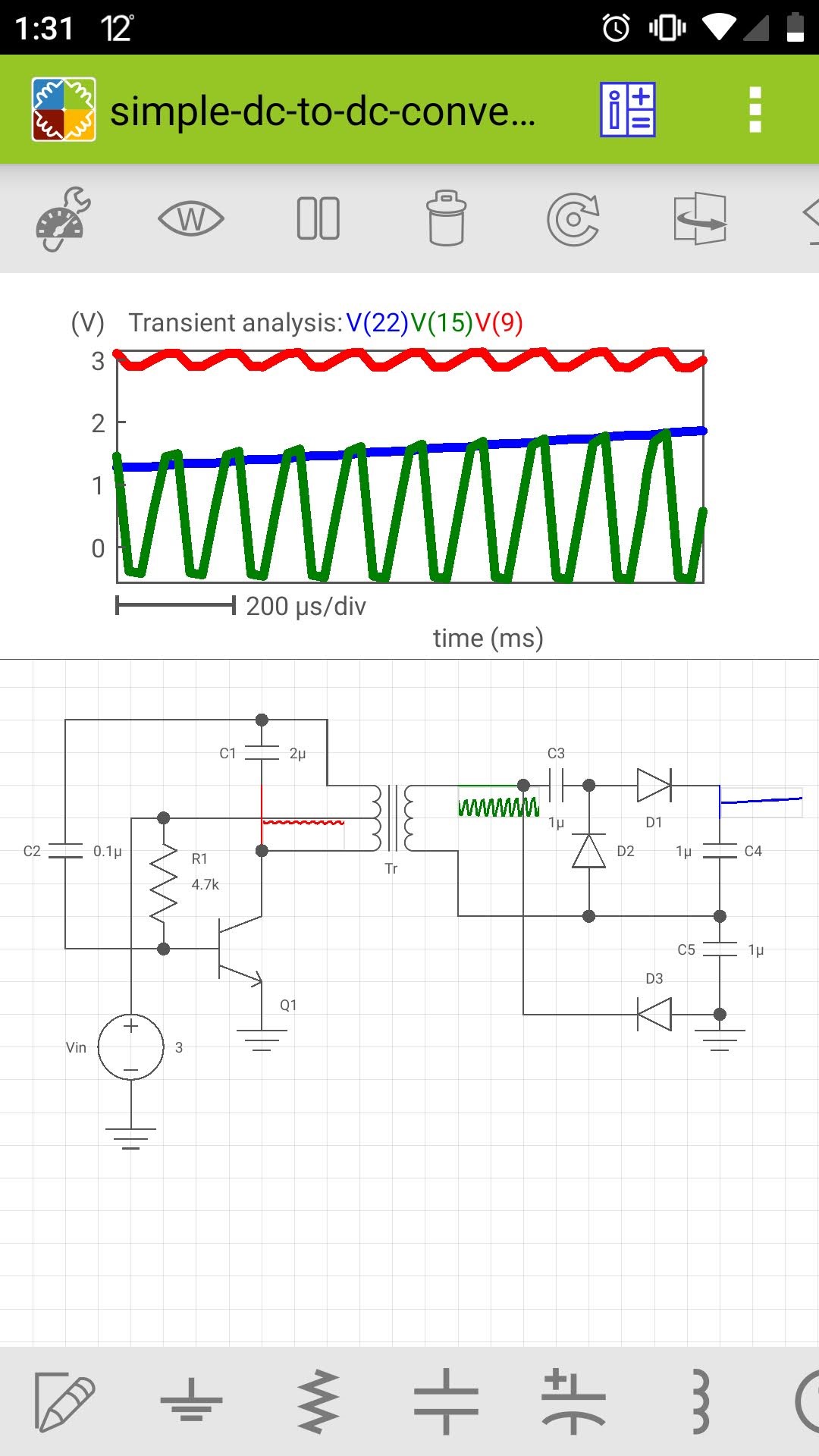
Simulating on my mobile phone, I obtain the following graphs for the input voltage, the output voltage and the secondary voltage of the transformer.
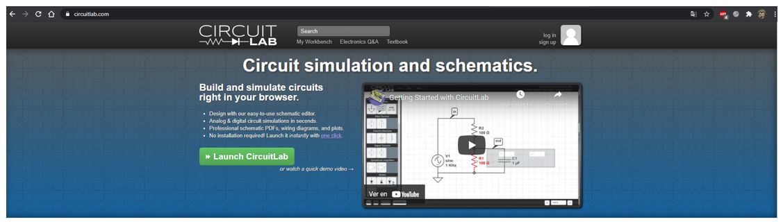
2. Circuilab:
It is a free website that allows you to use the Circuilab simulator in a new window that allows you to work with the simulation of basic circuits. (https://www.circuitlab.com/ )
On the right side, you have a tool with the library of components that can be attached. (Activating the Build button).

and when pressing the Simulate button, the options to configure the simulation appear.
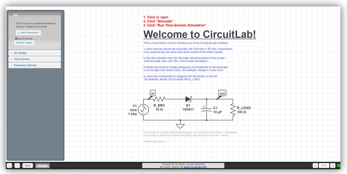
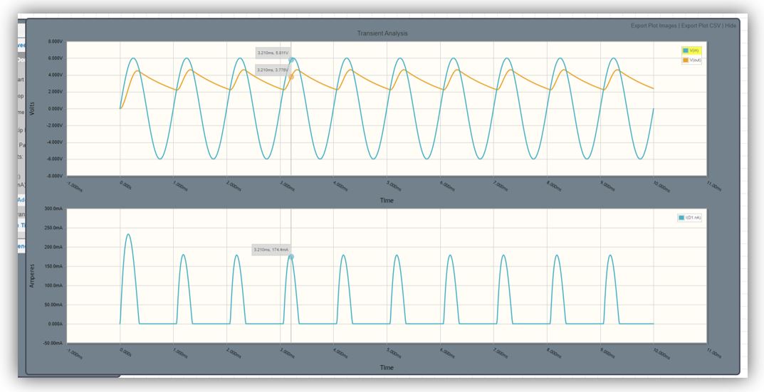
I'm going to simulate the example that comes on the page.
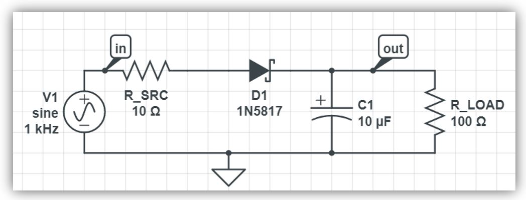
In the graph above, you can see the input voltage (Vin) in blue, and the output voltage (Vout) in red.
In the graph below, the current in the diode (Id1) is shown.
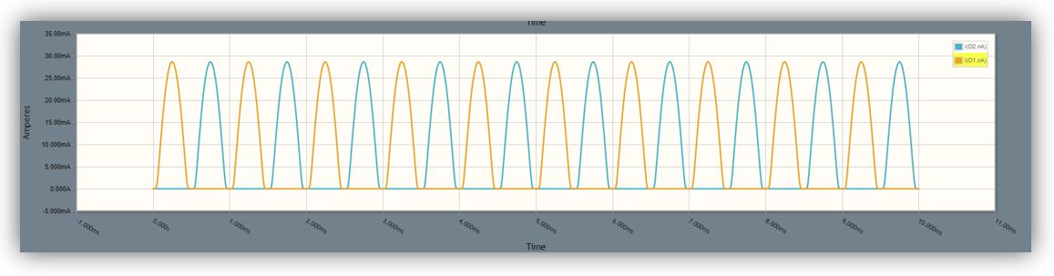
Now I am going to draw a simple circuit. I am going to use an AC source, a resistor and two diodes

I have connected a probe to the output of the source to see the voltage at the input (the 5V of the source). I have connected another probe to the output, to see how the voltage drops due to the action of the resistor.
Also I have connected another point to measure the intensity in the resistor.
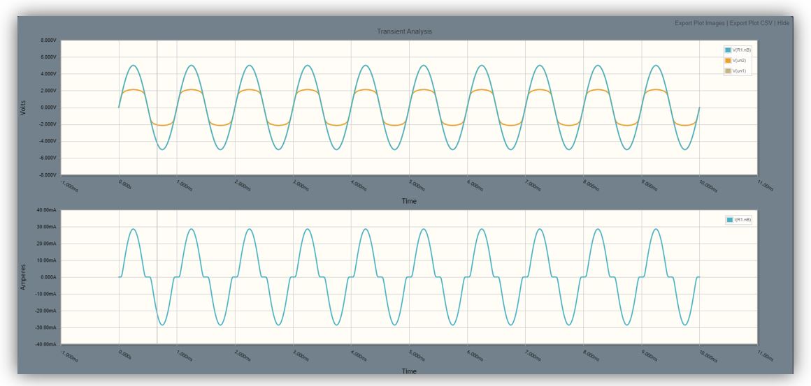
To see when each diode acts, I have placed a measurement point on each of them. You can see which of them is activated in each cycle of the sine wave.
5.- FILES
Firmwares ATTiny 44 & 45 and rulesFiles PNG board ATTiny44
Led_on_of code
MyATtiny 44 HelloBoard
6.- Experience and conclusions from WEEK6
I have made a new milled electronic board and programmed it. I was truly happy to see that the physical result has worked. It has been a good experience to learn more about making electronic boards and how to program them. Luckily no problems.
As an additional, I looked for circuit simulators that were free and I was surprised with the couple of results that I found. It is a week in which I have improved my knowledge about electronic boards.
“What went wrong”: At first I did not handle the automatic routing tool well. But little by little I have been improving with its use although almost always it is necessary to give it a manual review.
“What went well”: The manufacture of electronic circuits with Eagle was comfortable and easy for me.
“What will you do differently next time”: It would be interesting to try other software such as OrCAD and some payment simulation software, although they are usually expensive.