Week 4
Electronics Production
This week, for electronic production, we dealt with PCB milling machine and electronic components. We did soldering as well as programming.
The individual assignment for this week was to make an in-circuit programmer by milling and stuffing the PCB,
and to test it.
I started by using a PCB design and using mods to send the design in png format to the milling machine.
Using Modella MDX20
The Roland Modela MDX-20 is a small milling machine and a 2 1/2D precision scanner.This machine is mostly used for milling circuit boards, though it can also mill in other soft materials like machinable wax. For milling circuit boards you should export you design into a black&white monocroome png. For milling out 3 dimensional molds you should export your design as .stl. The second use of this machine is scanning. It uses a thin needle to gently touch the object and calculates from this a 2 and a half dimensional model. Though slow at processing, it can create a high detailed model. We use the fab modules to give commands to the Modella and run the cutting program. This machine is very delicate and the bits are very fragile, take care in removing the milling cutters and correcting the zero setting. Modella MDX 20 behaves like an ordinary 3-Axis CNC machines, Each axis is driven by a stepper motor and the cutting program tells the machine where to go by giving coordinates to the machine in real time. We have two milling processes in cutting a PCB, The first one is milling the traces to get the circuit board pattern, and the second is cutting out the board from the base material. For milling traces, we use the 1/64th inch (0.4mm) bit and for cutting 1/32th (0.8mm) inch bit. The Modela MDX20 is a Desktop 3D scanning and Milling machine by Roland. Easy to use, compatible with popular softwares, powerful and can directly connect to the computer via RS232C cable.
For this week, the circuit was given in image format.
.png)
I opened mods and sent this file to the machine and set the origin and started with tracing the circuit. For this I used the 1/64 mills bit to trace the inner circuit. This was also selected in mods.
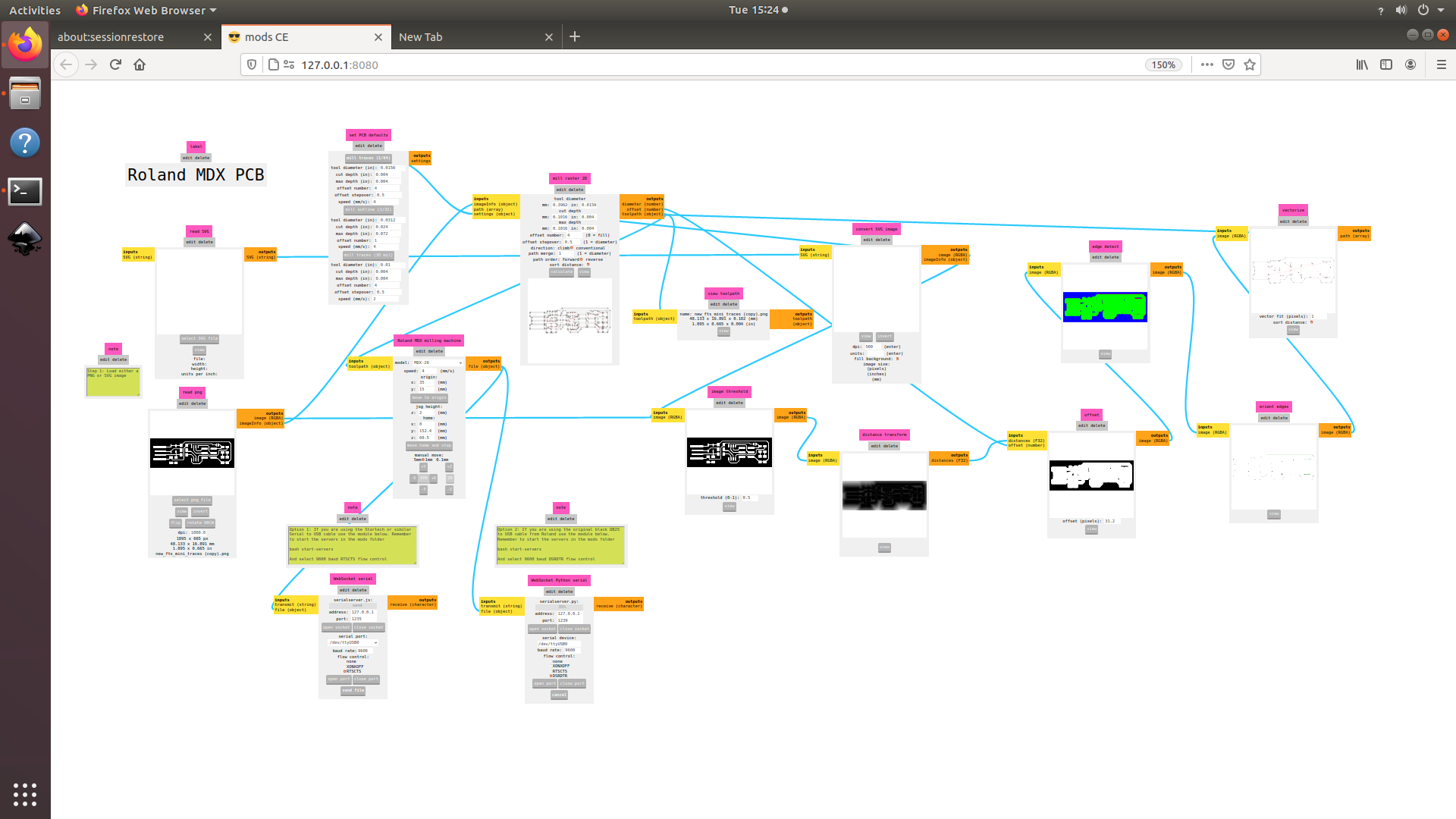
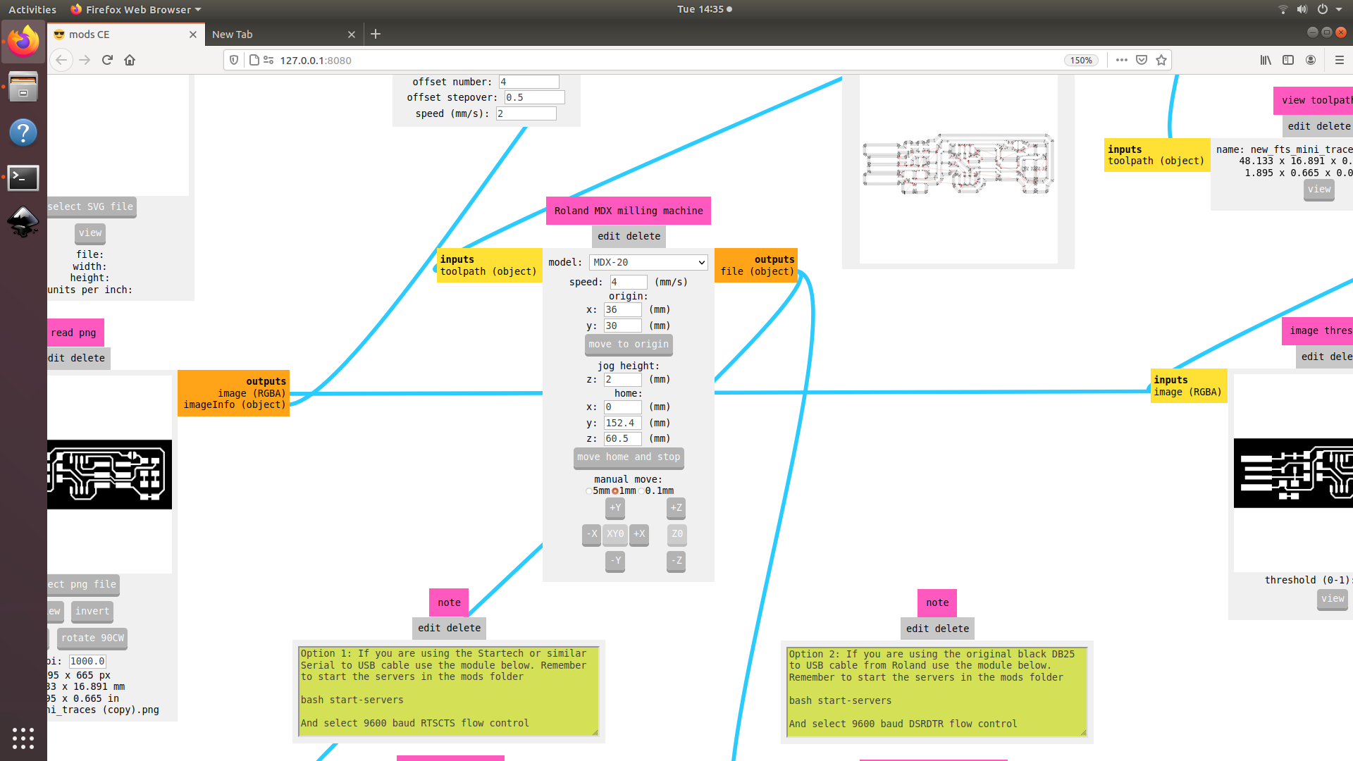
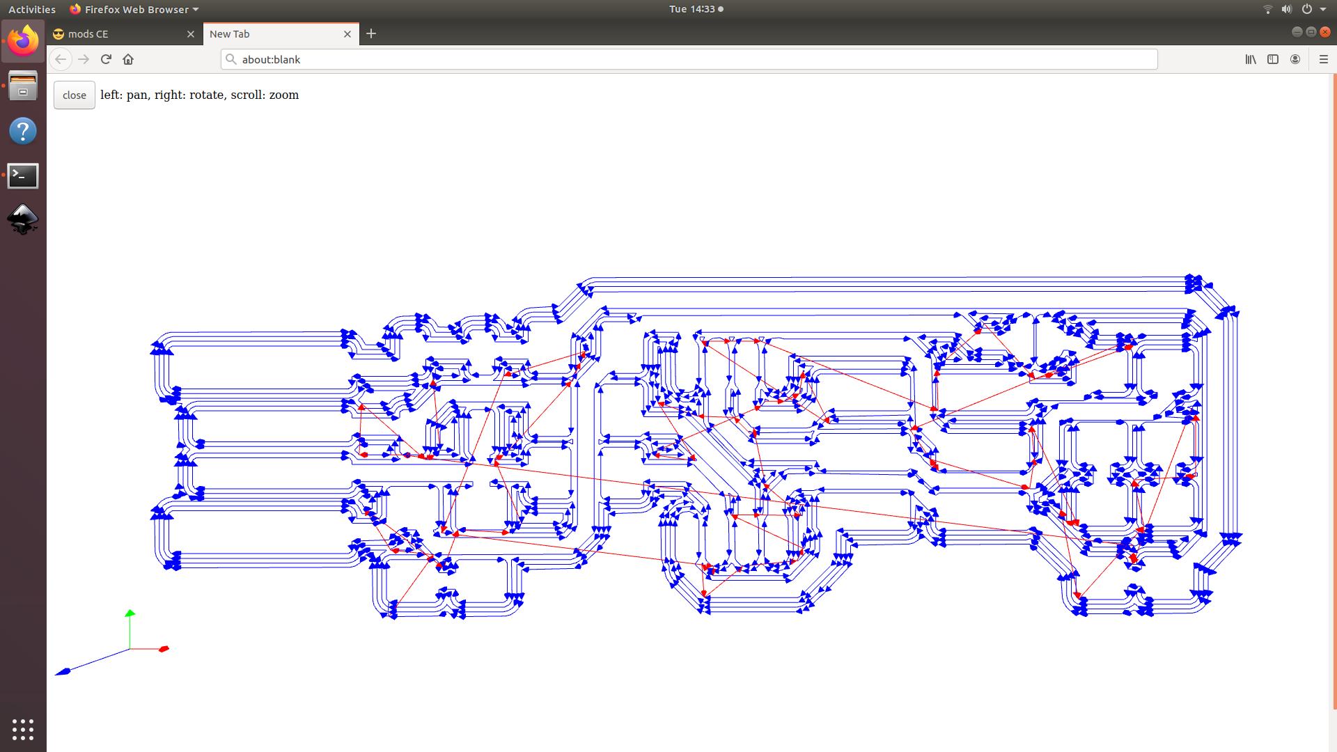
Once the design was uploaded, the lines were calculated and this was the view.
I then started the process by controlling it through mods.
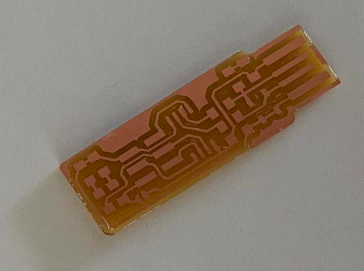
The final circuit board looked like this.
Soldering components
Once the PCB was done, I took all the components required.
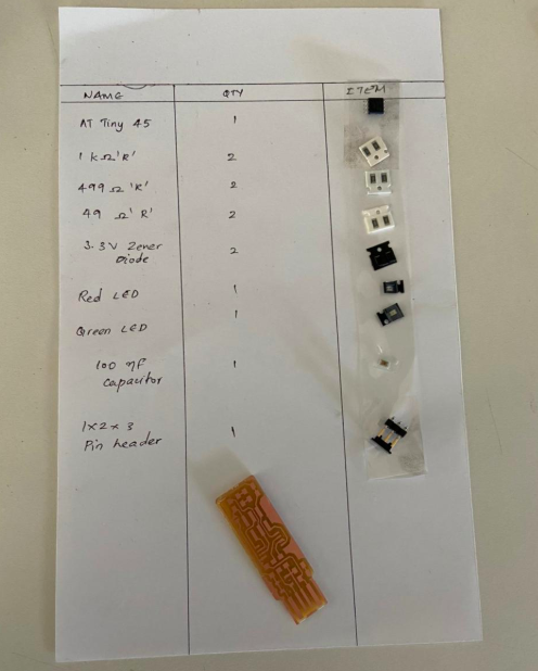
The next step was to assemble the components on the board and solder it.

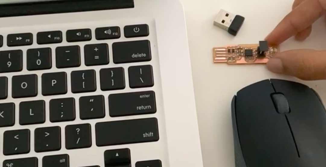
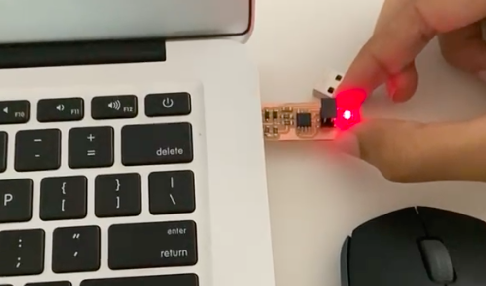
Once the soldering was completed, I tested it to see if there is any issues with the circuit.
Group Assignment
This week's Group Assignment was to characterize the design rules for our PCB production process. Initially we milled our test pad with 1/64 bit and chose to mill one board with offset as 4. Then we tried the 1/32 bit.
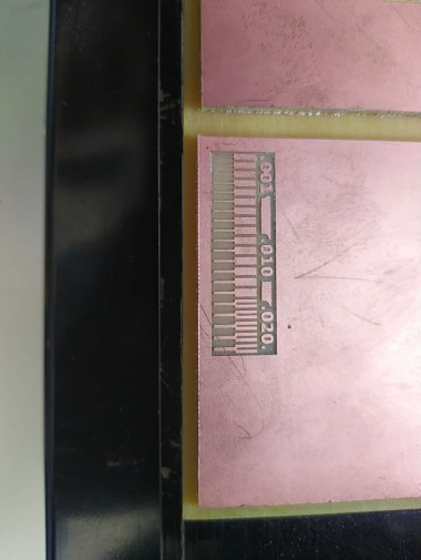
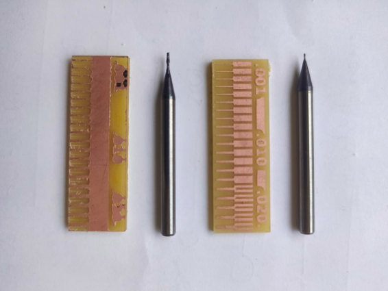
This image clearly shows the difference in milling resolution of 1/32 and 1/64 bits. Usually we use the 1/64 bit for milling trace and 1/32 for cutting and drilling. So it is okay of drilling and cutting.
Programming the PCB
Plug the board into a USB port. USB2.0 is preferred over 3.0 if you have one, and use an extension cable so that you do not put strain on your board especially if your port is upside down. If you installed the red LED, it should be lit up now. If not, check the solder jumper and make sure that it is bridged. If your computer complains about a USB device drawing too much power, unplug the board and check for shorts. Connect the programmer to the ISP header on your board. Note that there are two different orientations in which you can connect the cable; it is imporatant that you get pin 1 in the right place. Pin 1 is the MISO pin and it should be connected to the MISO pin of the board you are programming. Once you finish soldering the components, It is time to test the connections and program the board. Look carefully at the board to see if all the connections are proper. For Programming I referred the link First we need to install all necessary software for programming, which include "Avrdude" and "GCC" To install these softwares in Ubuntu, Open the terminal and follow the steps :
sudo apt-get install flex byacc bison gcc libusb-dev avrdudeNow we need to download and unzip the firmware To download and unzip the FABISP firmware, Open the terminal and follow the steps :
sudo apt-get install gcc-avr
sudo apt-get install avr-libc
sudo apt-get install libc6-dev
cd ~/DesktopThe "Makefile" in the downloaded firmware is set up to work with AVRISP2 by default, Since we are using Atiny45 this firmware wont work. So you can use this file My programmer cannot communicate with the computer directly, so I connected it to an already programmed programmer which can communicate with the computer and translates the messages to my programmer.
wget http://fab.cba.mit.edu/classes/863.16/doc/tutorials/fabisp_programming/fabISP_0.8.2_firmware.zip
unzip fabISP_0.8.2_firmware.zip
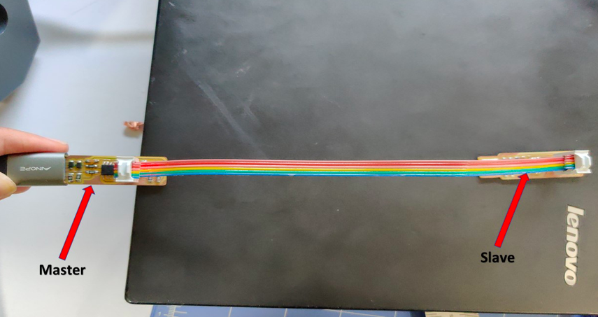
The "Makefile" in the downloaded firmware is set up to work with AVRISP2 by default, Since we are using Atiny45 this firmware wont work. So you can use this file
Programming FABTINY ISP
Follow the steps to run the device:
to the unziped firmware folder and open the terminal.
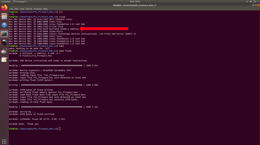
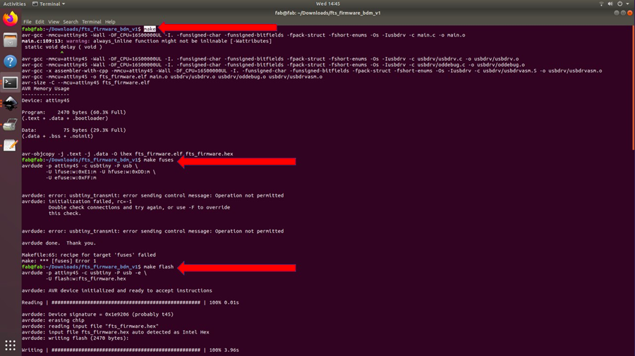
type "make"
type "make flash"
type "make fuses"
"make rstdisbl"
Blow the resent fuse
We need to change the bit that will turn the ATtiny45's reset pin into a GPIO pin.This will disable our ability to reprogram this ATtiny45 in the future, hence make sure everything is working before doing this. Connect your ISP programmer to your board one more time, and in the Terminal run. For that you need to type:
make rstdisbl.
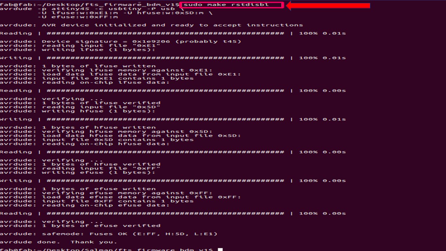
This does the same thing as the make fuses command.with that, avrdude will never be able to talk to this chip again through the ISP header. Now our programmer is finished. To check the disabled pin. We can use the following command.
make flash