Week 10
Input Devices
In the tenth week of Fablab, we got introduced to various sensors to get inputs. We all tried a sensor each to understand the working and look out for applications. I used the doppler Radar sensor and made a motion detector.
Individual Assignment
The individual assignment for this week was to design and use a sensor, add a sensor to a micro controller board that I have designed and read it
Doppler Radar Sensor
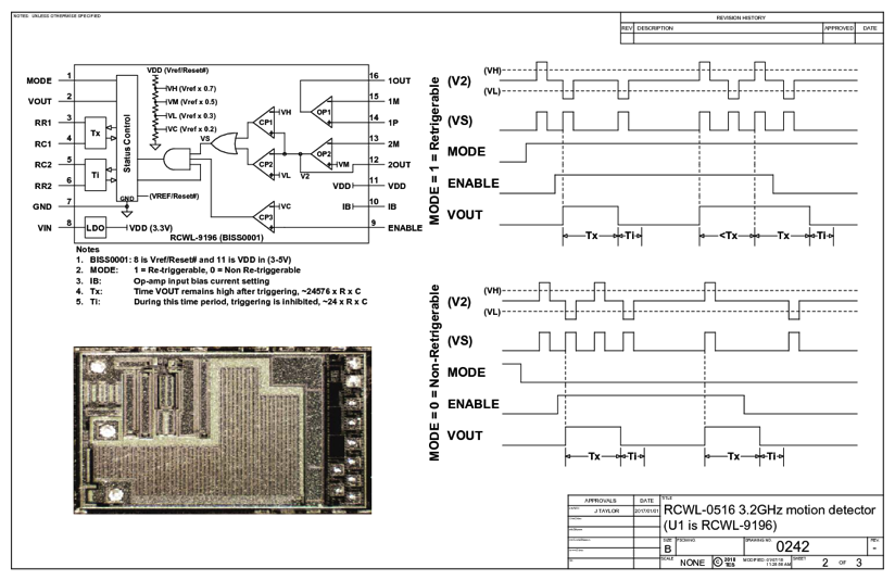
The RCWL-0516 is basically a motion detection sensor. It can recognize motion via doppler microwave technology with the help of walls or other materials. It will be triggered not only by the presence of people but also by other active objects. RCWL-0516 sensor utilizes the Microwave Doppler radar technology to recognize active objects. The Doppler radar operates by transferring a microwave signal to a target and then monitoring the change in the frequency of the returned signal. The imbalance in the received signal frequency can also support to estimate of the target’s velocity with respect to the radar. This sensor module utilizes an RCWL-9196 chip that helps repeat triggers and a 360-degree detection area with no blind spot. It can recognize motion via walls and other materials and have a susceptibility range of 7 meters.
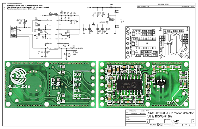
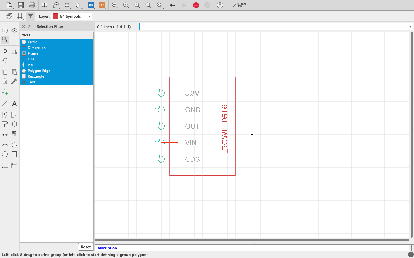
The schematic of the sensor board that I used is shown below.
The specifications of the sensor is as follows:
Input Voltage – 4V to 28V
Operating current – 3mA (max.)
Operating frequency – 3.2GHz
Transmission power – 30mW (max.)
Regulated output voltage – 3.3V, max. 100mA
Sensing distance – 5 to 7 meters
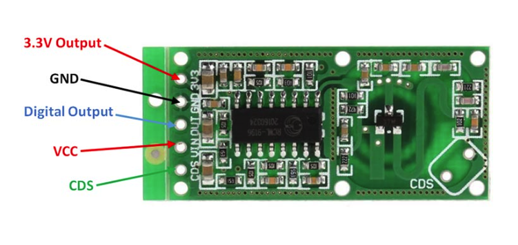
The module pinout of the sensor is given in the image below
I started off by designing a circuit for the same using Eagle. First, I selected all components from the library and then connected all the components. All major components were available in the fab library, but I had to draw and create the library for the sensor. I checked the number of pads and the details and then created a library with RCWL-0516.
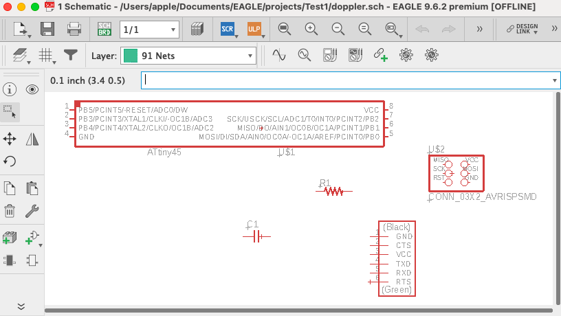
Once the schematic was completed, I arranged and autorouted the circuit. I had to do it a few times and get some adjustments done, to finally get it done.
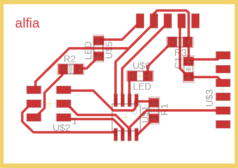
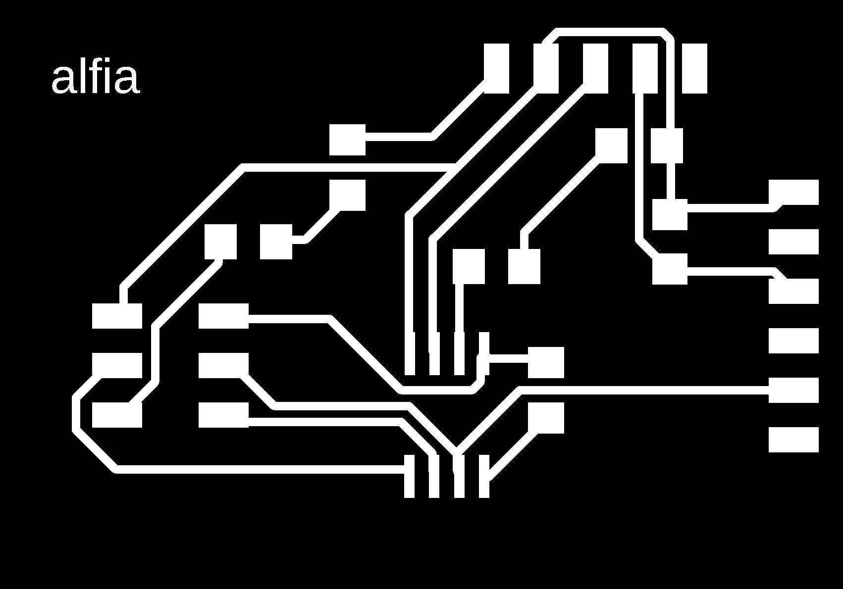
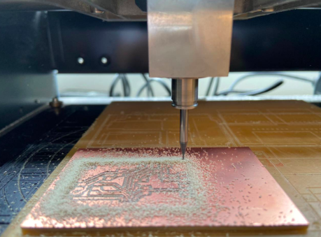
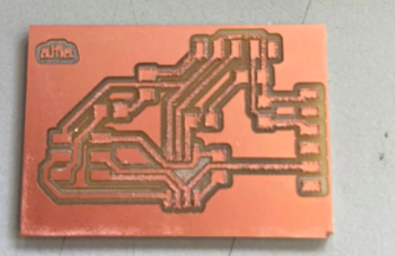
After exporting the circuit trace, I went ahead and milled the board.
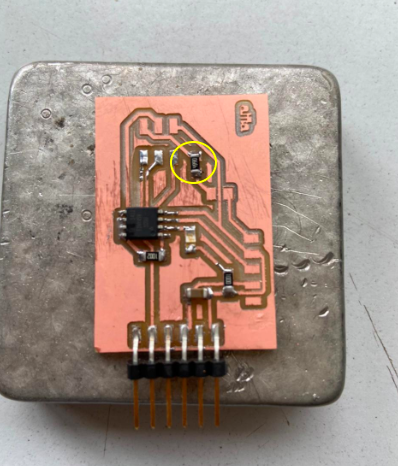
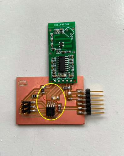
My initial design includes an LED and resistor which was accidentally connected to VCC and 3.3 V which I didnt notice at first. I noticed this issue after I had the board milled and started soldering. To get this corrected, I first shorted the circuit by replacing the LED and resistor using two 0 ohm resistors. Then A copper wire to connect other two unconnected regions of the circuit.
Once all the soldering, troubleshooting and fixing circuit was done, I had to program the board and see if it was working. I did the program in Arduino and first burnt the bootloader and then uploaded the program. The program I used is given below.
int Sensor = 4; //Input Pin
int LED = 3; // Led pin for Indication
int flg = 0; //Change detection flag
void setup() {
pinMode (Sensor, INPUT); //Define Pin as input
pinMode (LED, OUTPUT); //Led as OUTPUT
}
void loop() {
int val = digitalRead(Sensor); //Read Pin as input
if((val > 0) && (flg==0))
{
digitalWrite(LED, HIGH);
flg = 1;
}
if(val == 0)
{
digitalWrite(LED, LOW);
flg = 0;
}
delay(100);
}
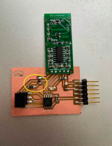
Once it was uploaded, I tested the sensor and it worked!
Some Calculations
If ft is the transmitted frequency, fr is the reflected frequency (as measured by the common transmit/receive antenna on the sensor), v is the speed of the target relative to the sensor (negative if receeding, positive if advancing toward sensor), c is the speed of light and fd = (fr-fd) is the doppler shift, then:
fr = ft (c + v) / (c - v)
fd = fr - ft = 2v ft / (c - v)
If ( c << v) then fd ≈ 2v ft / c
Assume typical human motion speed of v = 1 m/s. ft = 3.181GHz, c = 2.998E8 m/s, then fd = 10Hz.
Files
The ino file can be downloaded from here
The schematic and board files can be downloaded.