8. Embedded programming
Group Assignment : compare the performance and development workflows for other architectures
We tried three types of architectures as below.
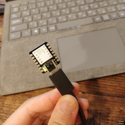
Seeeduino XIAO
The Seeeduino XIAO is the smallest member of the Seeeduino family. It carries the powerful ATSAMD21G18A-MU which is a low-power microcontrollers. On the other hand, this little board has good performance in processing but needs less power. As a matter of fact, it is designed in a tiny size and can be used for wearable devices and small projects.
ref:Seeeduino XIAO Official Site
Environment Setting
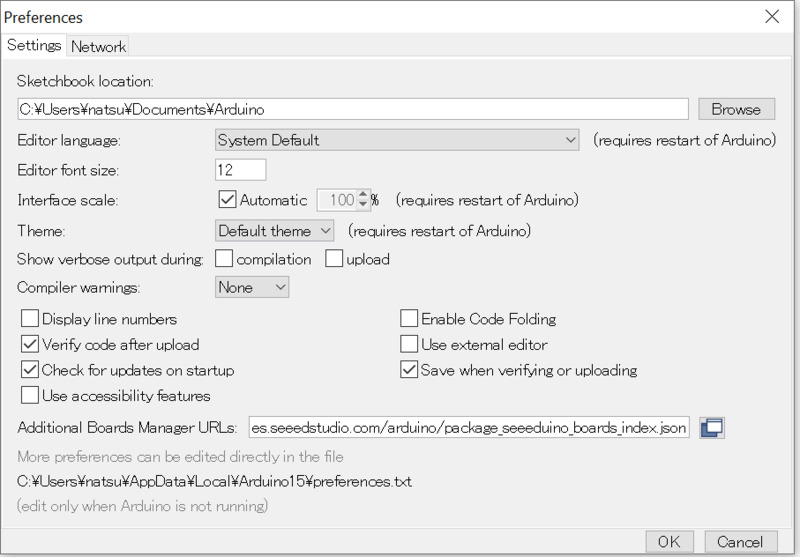
1.Add Seeeduino to Arduino IDE
Arduino IDE>Preferences>Additional Boards Manager
Add URL below.
https://files.seeedstudio.com/arduino/package_seeeduino_boards_index.json
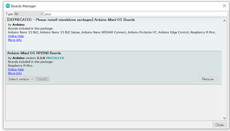
2.Install the board
Tools>Board>Boards Manager Search “Seeeduino XIAO” and install the board.
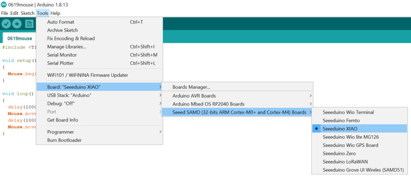
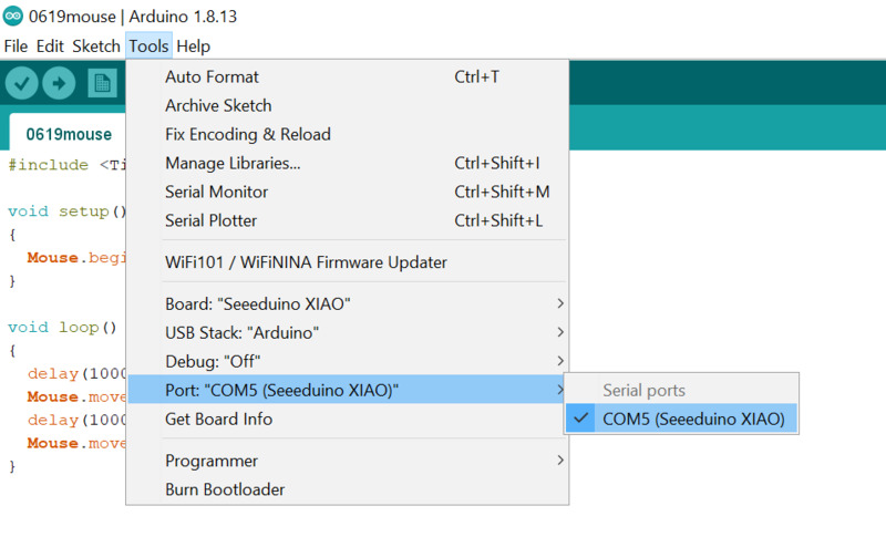
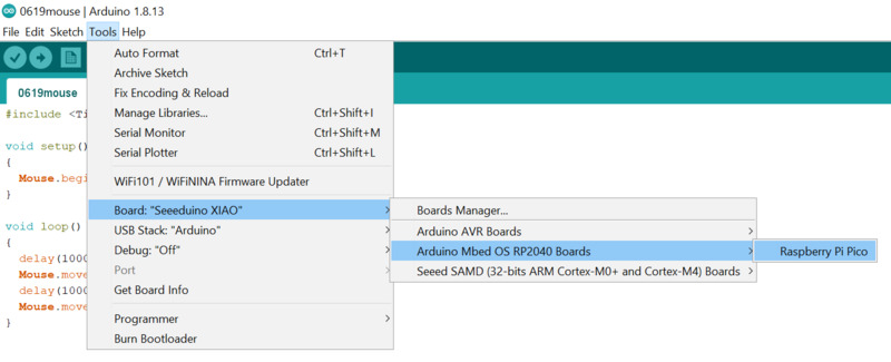
3.Select the board and port
Tools>Board
Select “Seeeduino XIAO”
Tools>Port
Select appropriate port which is shown.
Make LED Brink
Program
void setup() {
  // initialize digital pin LED_BUILTIN as an output.
  pinMode(LED_BUILTIN, OUTPUT);
}

// the loop function runs over and over again forever
void loop() {
  digitalWrite(LED_BUILTIN, HIGH);   // turn the LED on (HIGH is the voltage level)
  delay(1000);                       // wait for a second
  digitalWrite(LED_BUILTIN, LOW);    // turn the LED off by making the voltage LOW
  delay(1000);                       // wait for a second
}
Result
Select a pin and make another LED brink
There are four built-in LED on Seeeduino Xiao. In this program, we tried to select a pin and make specific LED brink.
Program
const int ledPin_L =  13;      // Yellow
const int ledPin_R =  12;      // Blue
const int ledPin_T =  11;      // Blue

void setup() {
  // initialize digital pin LED_BUILTIN as an output.
  pinMode(ledPin_R, OUTPUT);
}

void loop() {
  digitalWrite(ledPin_R, HIGH);   // HIGH OFF
  delay(3000);
  digitalWrite(ledPin_R, LOW);    // LOW ON
  delay(1000);
}
Result
Make a Mouse
Next we tried to make the mouse with Seeeduino Xiao.
ref. Seeeduino XIAO | マウスふるふるを作る
Firstly, we needed to install the library for it.
ref. TinyUSB Mouse and Keyboard library
Program
#includevoid setup() { Mouse.begin(); } void loop() { delay(1000); Mouse.move(50, 0); delay(1000); Mouse.move(-50,0); }
Result
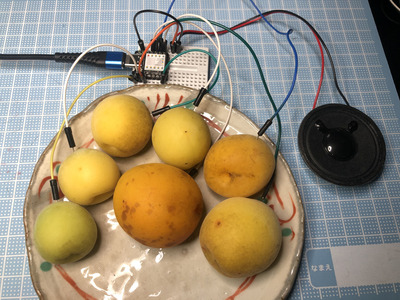
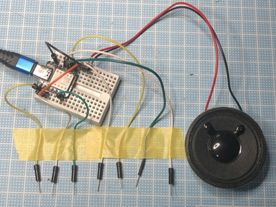
Make a Fruit Piano on Seeeduino XIAO’s Q-Touch Function
Seeeduino Xiao has Q-Touch Function. With using it we could make piano with the fruit!
ref. How to Make a Fruit Piano on Seeeduino XIAO’s Q-Touch Function
Program
#include "Adafruit_FreeTouch.h"
#define SPEAKER 2
Adafruit_FreeTouch qt_1 = Adafruit_FreeTouch(A0, OVERSAMPLE_4, RESISTOR_50K, FREQ_MODE_NONE);
Adafruit_FreeTouch qt_2 = Adafruit_FreeTouch(A1, OVERSAMPLE_4, RESISTOR_50K, FREQ_MODE_NONE);
Adafruit_FreeTouch qt_3 = Adafruit_FreeTouch(A6, OVERSAMPLE_4, RESISTOR_50K, FREQ_MODE_NONE);
Adafruit_FreeTouch qt_4 = Adafruit_FreeTouch(A7, OVERSAMPLE_4, RESISTOR_50K, FREQ_MODE_NONE);
Adafruit_FreeTouch qt_5 = Adafruit_FreeTouch(A8, OVERSAMPLE_4, RESISTOR_50K, FREQ_MODE_NONE);
Adafruit_FreeTouch qt_6 = Adafruit_FreeTouch(A9, OVERSAMPLE_4, RESISTOR_50K, FREQ_MODE_NONE);
Adafruit_FreeTouch qt_7 = Adafruit_FreeTouch(A10, OVERSAMPLE_4, RESISTOR_50K, FREQ_MODE_NONE);
int BassTab[] = {1911, 1702, 1516, 1431, 1275, 1136, 1012}; //bass 1~7

void setup() {
  Serial.begin(115200);
  pinMode(SPEAKER, OUTPUT);
  digitalWrite(SPEAKER, LOW);
  //  while (!Serial);
  Serial.println("FreeTouch test");
  // initialize digital pin LED_BUILTIN as an output.
  pinMode(LED_BUILTIN, OUTPUT);

  if (! qt_1.begin())
    Serial.println("Failed to begin qt");
  if (! qt_2.begin())
    Serial.println("Failed to begin qt");
  if (! qt_3.begin())
    Serial.println("Failed to begin qt");
  if (! qt_4.begin())
    Serial.println("Failed to begin qt");
  if (! qt_5.begin())
    Serial.println("Failed to begin qt");
  if (! qt_6.begin())
    Serial.println("Failed to begin qt");
  if (! qt_7.begin())
    Serial.println("Failed to begin qt");
}

int qt_Threshold = 850;

void loop() {
  int qt1 = 0;
  int qt2 = 0;
  int qt3 = 0;
  int qt4 = 0;
  int qt5 = 0;
  int qt6 = 0;
  int qt7 = 0;

  qt1 = qt_1.measure();
  Serial.print(qt1);
  Serial.print(",");

  qt2 = qt_2.measure();
  Serial.print(qt2);
  Serial.print(",");

  qt3 = qt_3.measure();
  Serial.print(qt3);
  Serial.print(",");

  qt4 = qt_4.measure();
  Serial.print(qt4);
  Serial.print(",");

  qt5 = qt_5.measure();
  Serial.print(qt5);
  Serial.println();

  qt6 = qt_6.measure();
  Serial.print(qt6);
  Serial.println();

  qt7 = qt_7.measure();
  Serial.print(qt7);
  Serial.println();

  if (qt1 >= qt_Threshold) {
    sound(1);
  }
  if (qt2 >= qt_Threshold) {
    sound(2);
  }
  if (qt3 >= qt_Threshold) {
    sound(3);
  }
  if (qt4 >= qt_Threshold) {
    sound(4);
  }
  if (qt5 >= qt_Threshold) {
    sound(5);
  }
  if (qt6 >= qt_Threshold) {
    sound(6);
  }
  if (qt7 >= qt_Threshold) {
    sound(7);
  }
}
void sound(uint8_t note_index)
{
  for (int i = 0; i < 50; i++)
  {
    digitalWrite(SPEAKER, HIGH);
    delayMicroseconds(BassTab[note_index]);
    digitalWrite(SPEAKER, LOW);
    delayMicroseconds(BassTab[note_index]);
  }
}
Connection
Results
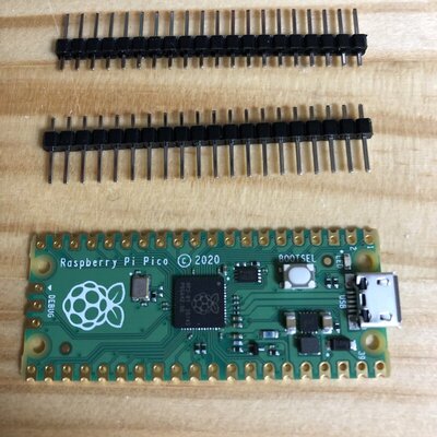
RaspberryPi Pico
Raspberry Pi Pico is a low-cost, high-performance microcontroller board with flexible digital interfaces. … RP2040 microcontroller chip designed by Raspberry Pi in the United Kingdom. Dual-core Arm Cortex M0+ processor, flexible clock running up to 133 MHz. 264KB of SRAM, and 2MB of on-board Flash memory.
Environment Setting
1.Install the board
Arduino IDE : updated to ver. 1.8.13
Tools > Board>Boards Manager > Search “Pico” > install “Arduino Mbed OS RP2040 Boards” (ver. 2.2.0)
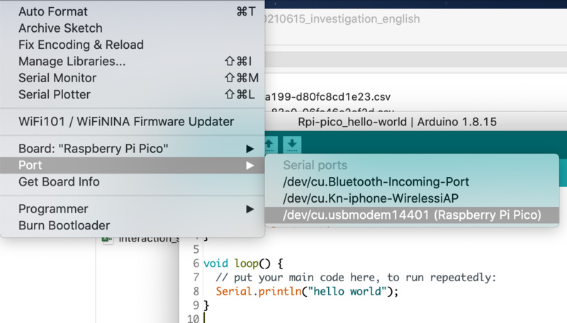
2.Select the board and port
Tool > Board > Arduino Mbed OS RP2040
Boards > Raspberry Pi Pico
Tools>Port
Select appropriate port which is shown.
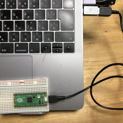
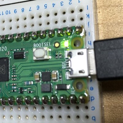
Connection
PC - USB port - usb cable - Rpi Pico (micro USB)
connecting USB cable with pushing “BOOTSEL” button on Pico board
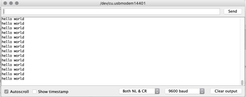
Show “Hello World” on the serial monitor
Program
void setup() {
  Serial.begin(9600);
}

void loop() {
  Serial.println("hello world");
}
Results
Make LED brinkBlink
program
void setup() {
  pinMode(25, OUTPUT);
}

void loop() {
  digitalWrite(25, HIGH);
  delay(500);
  digitalWrite(25, LOW);
  delay(500);
}
Results
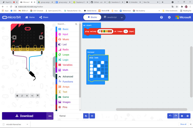
The Micro Bit
The Micro Bit (also referred to as BBC Micro Bit, stylized as micro:bit) is an open source hardware ARM-based embedded system designed by the BBC for use in computer education in the United Kingdom.
Program
We could easily write program by operating the blocks on the screen!
Is was easily understandable and visual-friendly interface.