6. Electronics design
The group assignment for week 6 was to use the test equipment in our lab to observe the operation of a microcontroller circuit board.
For test equipment, we have a multimeter and oscilloscope.
Multimeter
Fab lab Kannai has two multimeters. 1.TDX-200 ・We can check connectivity, voltage (range: large to small) , current and resistance. ・No beep, you have to check the error by the number on screen.
2.SANWA PM3 ・we usually use this one. ・We can check connectivity, voltage (range: large to small) and resistance.
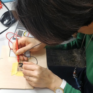
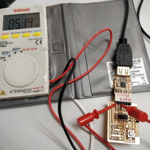
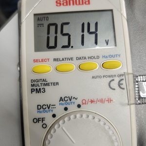
Checking the electromotive force of circuit board.
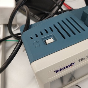
Oscilloscope
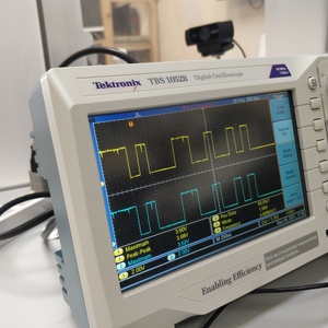
This is our oscilloscope at Fablab Kannnai.
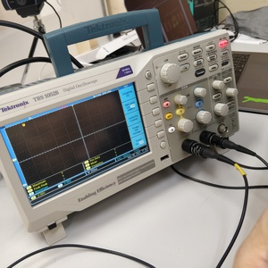
Press the power button on the top.
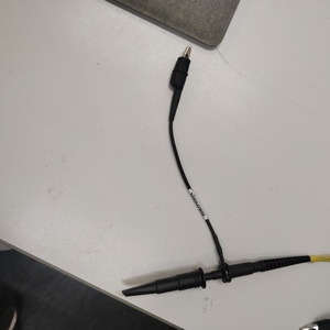
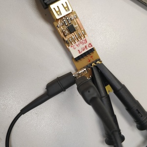
For checking with oscilloscope, we used hello.USB-serial.FT230x. Then we connected RX(Receiver) and TX(Transmitter) like the picture below.
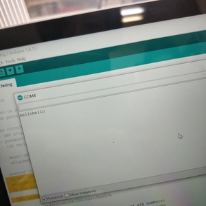
Then open Arduino IDE, select port, open Serial Monitor type one of 1-9. A-Z, a-z… -> and Send.
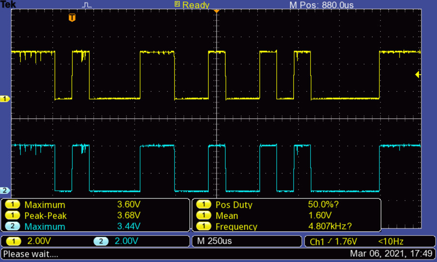
Signals showed in oscilloscope!
We can take the screenshot of the monitor. The following is when we typed “1 “and started a new line. The left half means “1” and right half means new line in binary. To find binary please check ASCII code.
This is when we tried Serial Communication Echo back and typed “hello”.
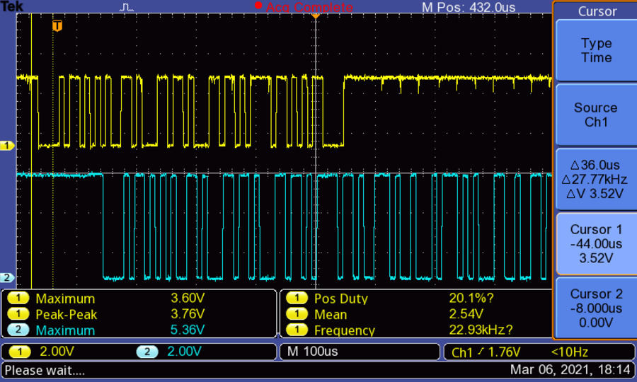
I was really amazed that I can read the letters from waveform on the monitor of oscilloscope. It was like cryptography and I felt like I can use this misterious waveform for design for textile or something to tell somebody hidden message…!