My individual part:
I have documented it in the Wired communication section.
- Design, build, and connect wired or wireless node(s) with network or bus addresses:
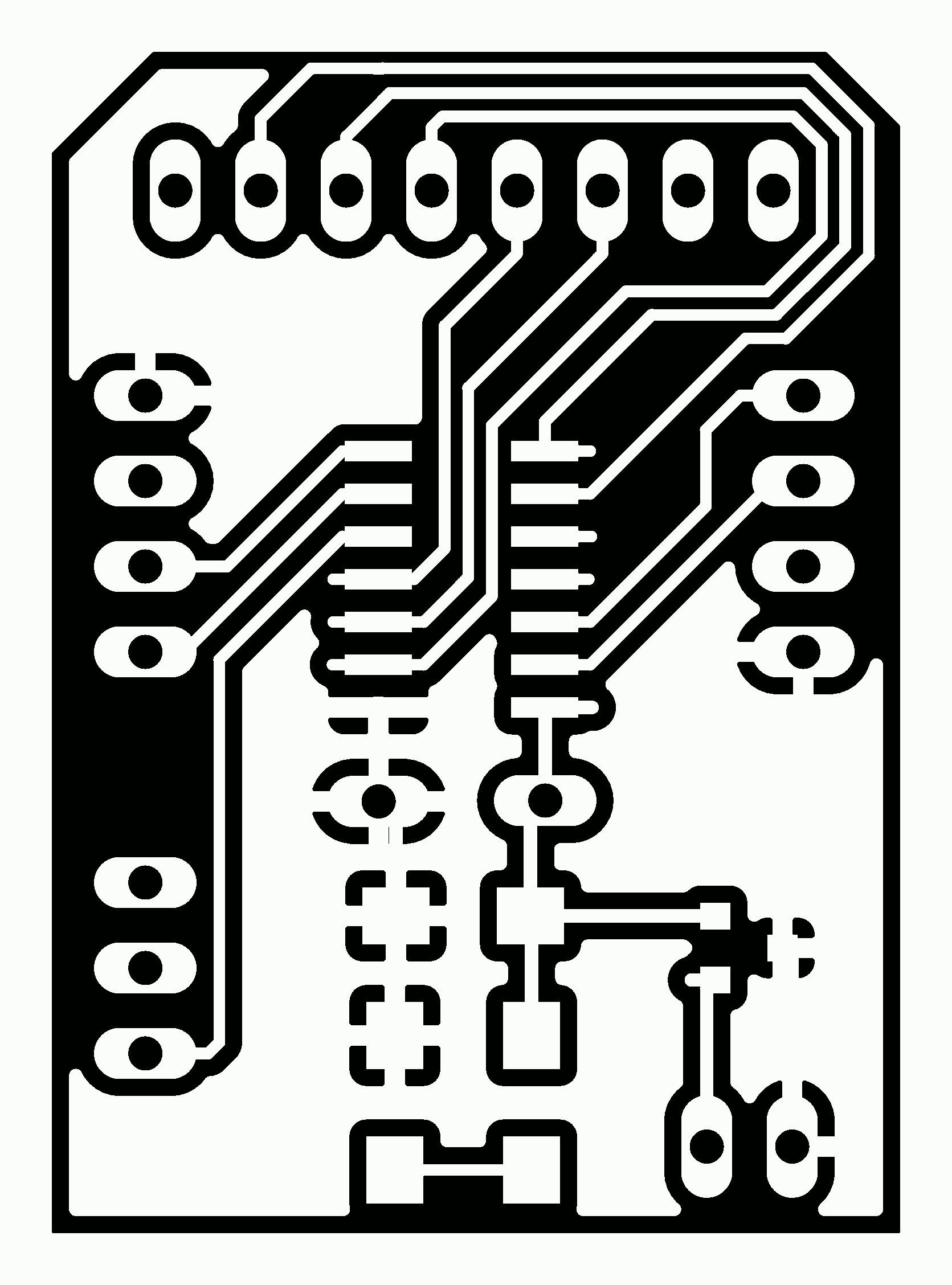
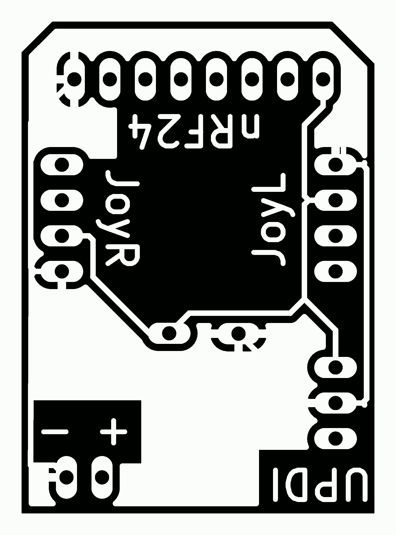
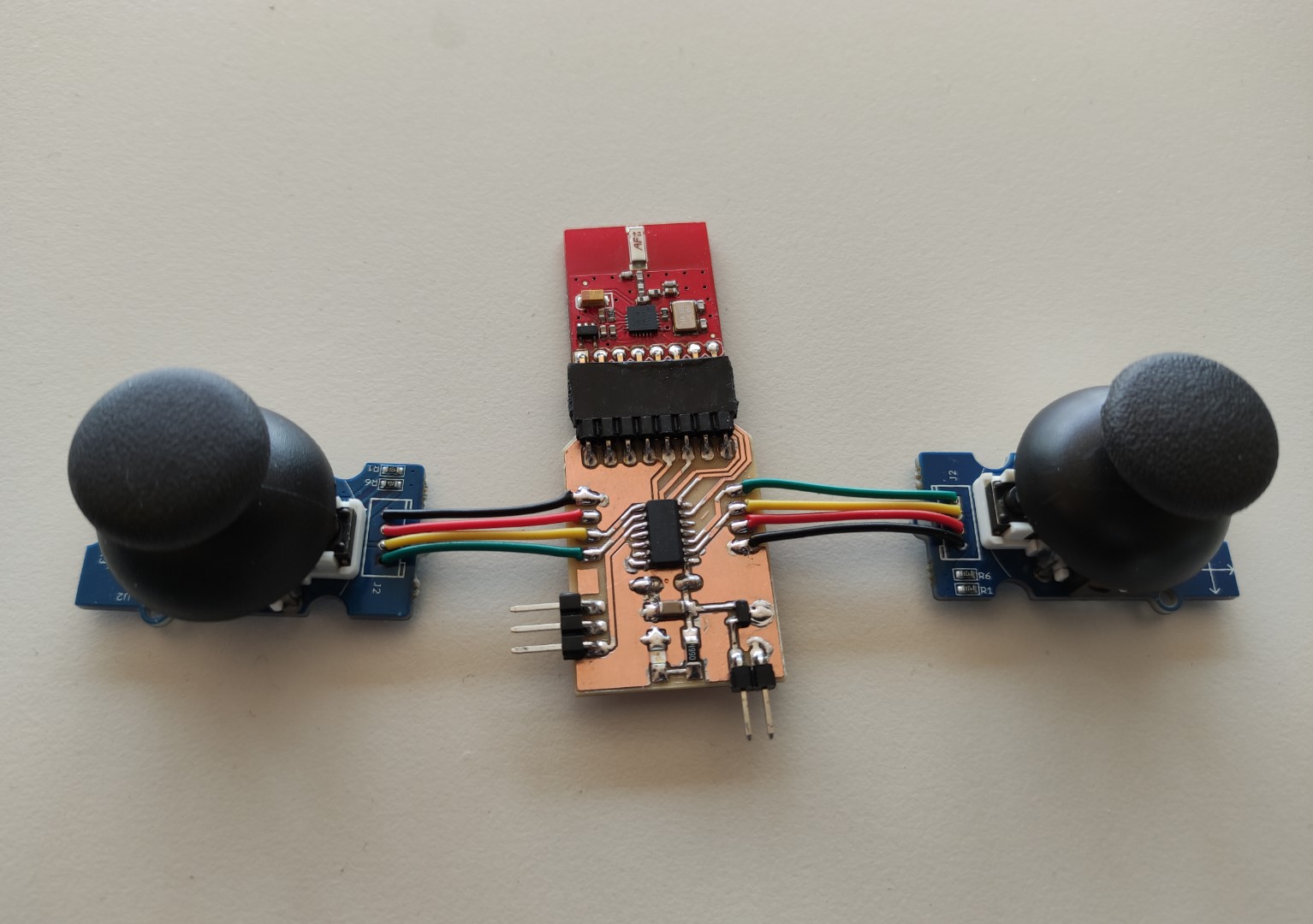
Since my final project consists on two parts: (1) the Omni-directional vehicle itself and (2) a remote control, for this assignment I made a remote control double-sided-board, which contains: Joysticks as Input and uses a nRF24 module for wireless communication.
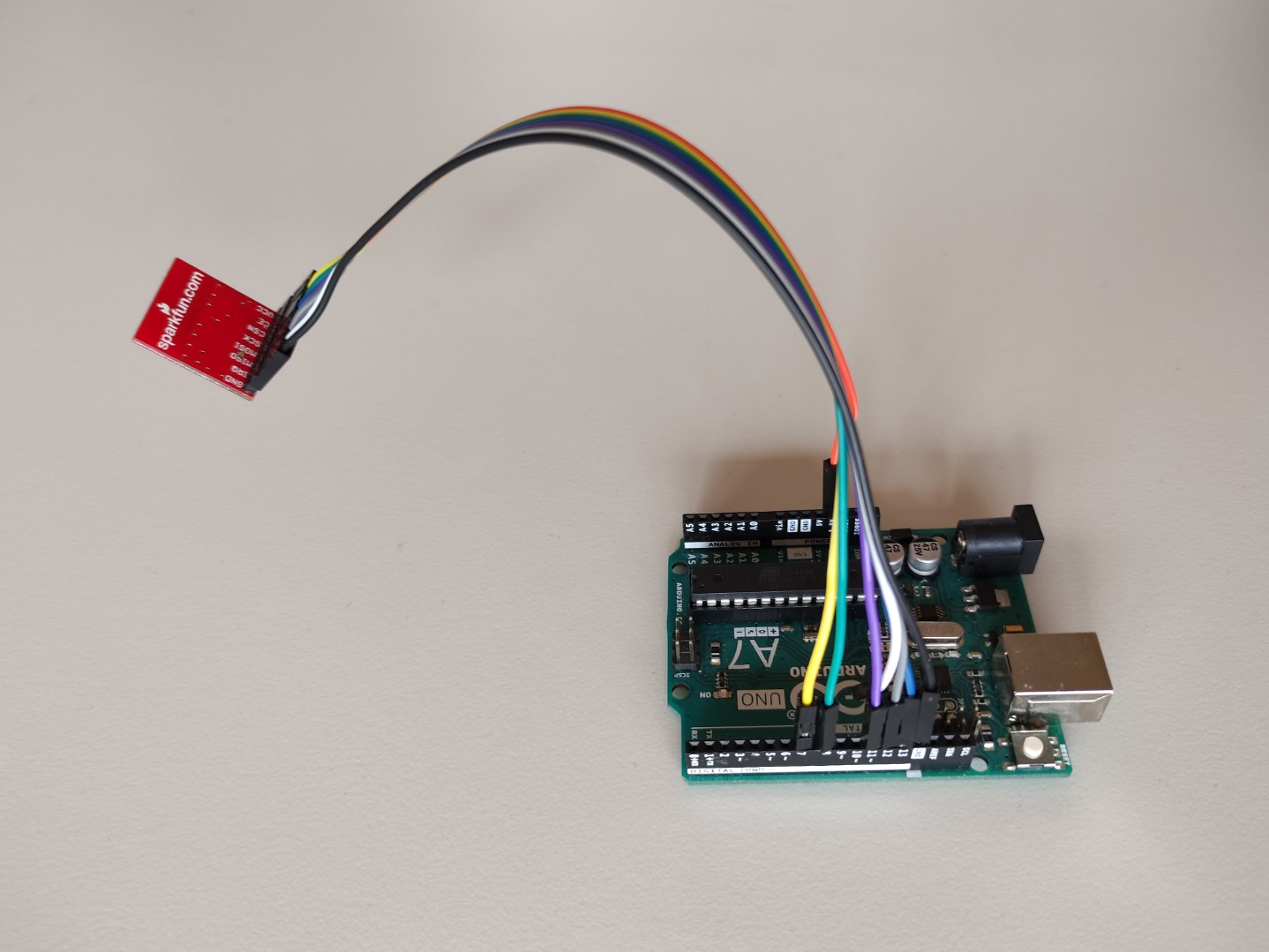
For testing a right communication performance, I used an Arduino UNO board with the same radio module as receiver.
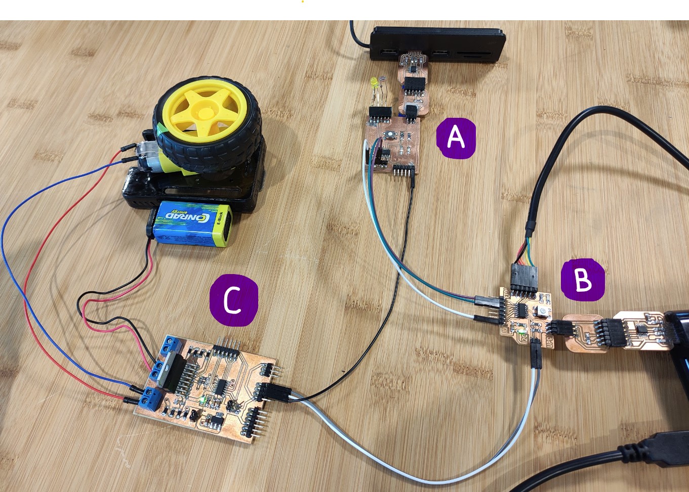
For this group assignment we had to communicate our boards with each other. They had to be from two different students, but since in this node we are three students, we just did it all together 😄
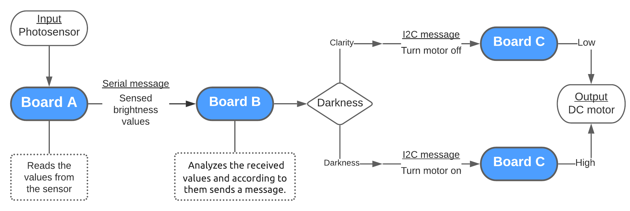
Sends the sensed values through serial connection to Board B.
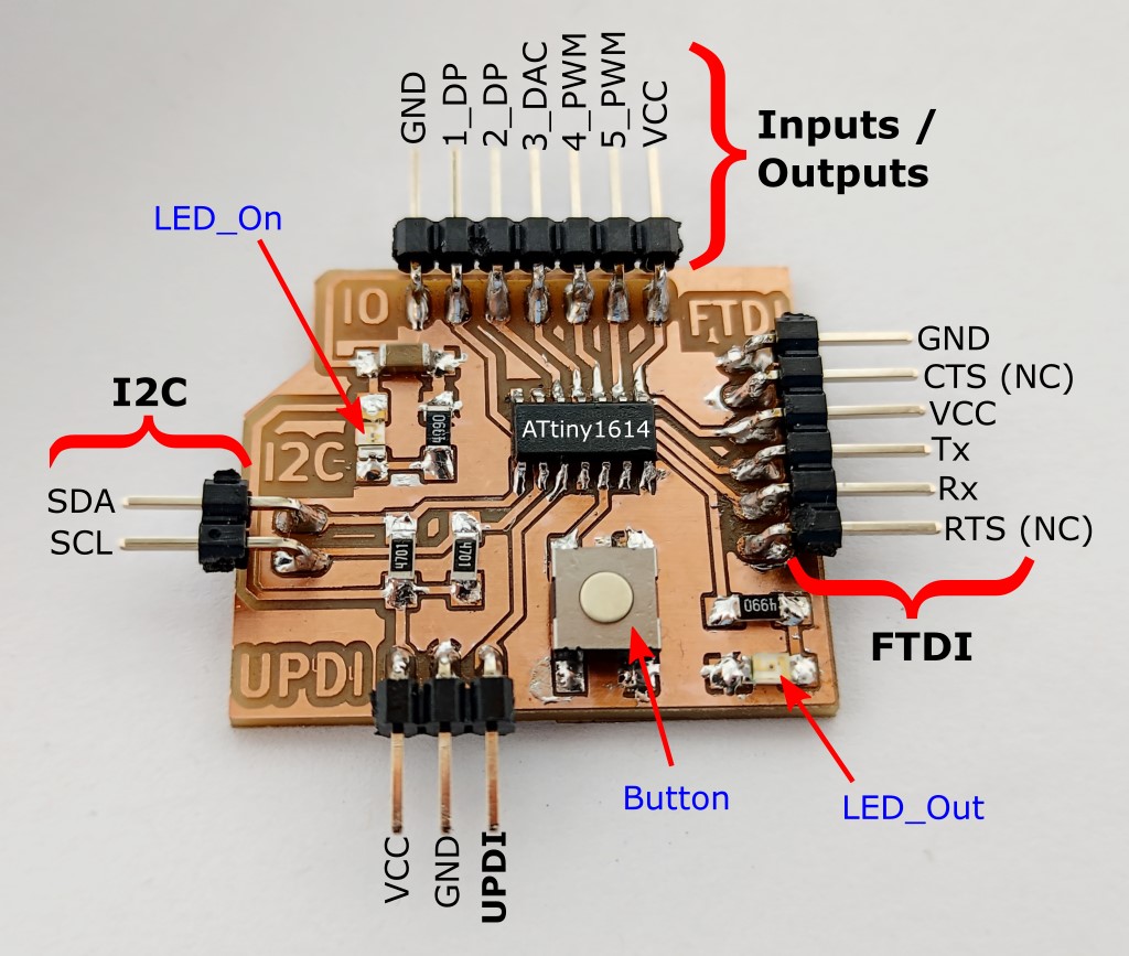
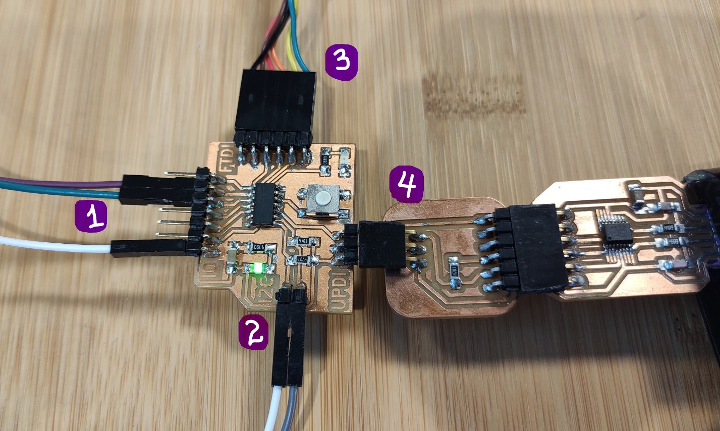
Board B:
1) is the Serial connection to Board A, receives sensed light intensity values; the board analyzes the values and according to them sends a message through ->
2) I2C connection to Board C, to turn the motor On or Off.
3) is FTDI for Serial monitor.
4) is UPDI for programming.
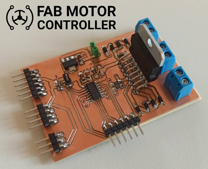
Board C:
Receives the messages from Board B to turn the DC motor On and Off.
Has a DC motor connected, powered by a 9V battery.
// ==========================// SENDER// ==========================#include<SoftwareSerial.h>SoftwareSerialsoftwareSerial(0,1);// RX, TXconstintsendPin=10;// LED pinconstintldrPin=9;// LDR pinvoidsetup(){Serial.begin(9600);softwareSerial.begin(9600);pinMode(sendPin,OUTPUT);pinMode(ldrPin,INPUT);Serial.println("Sender ready");}voidloop(){// Read ldr valueintldrStatus=analogRead(ldrPin);/** Serial Monitor for debugging **/Serial.print("[SENDING] Data: ");Serial.println(ldrStatus);// Displays the value of "ldrStatus" on the serial monitor/** Send data to Reciver **/softwareSerial.write(ldrStatus);if(ldrStatus<=500){digitalWrite(sendPin,HIGH);// for debugging//Serial.println("[STATUS] Its DARK Turn ON the LED");}else{digitalWrite(sendPin,LOW);// for debugging//Serial.println("[STATUS] Its BRIGHT Turn off the LED");}delay(200);}
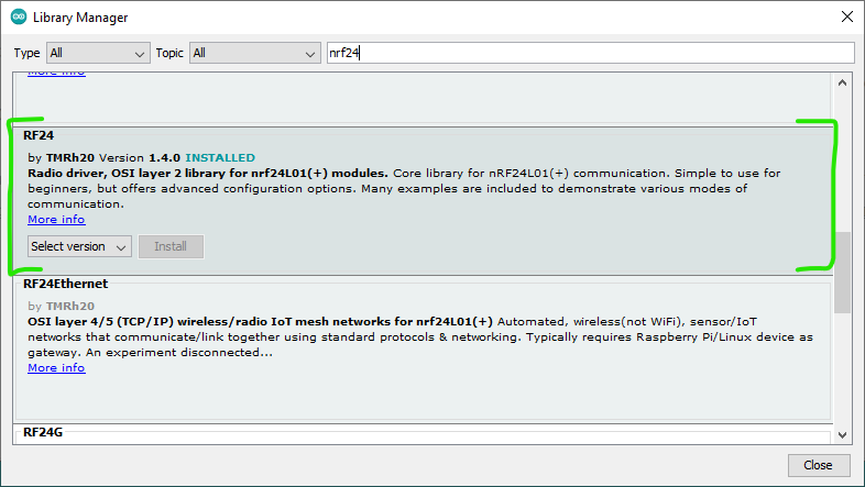
First I had to install the library that my colleague developed as his practice for this week.
In the case of my board, since I was already using the Rx and Tx of the microcontroller for the FTDI connection with the laptop for Serial monitor, I have used softwareSerial(Rx, Tx) to have serial communication with Board A.
To be able to connect another node to my board I could simply use another softwareSerial(Rx, Tx) with two of the three pins left that I have.
// ===========================// Receiver// ==========================/* Made by Jefferson Sandoval in collaboration with Harley Lara * for the Embedded Networking and Communications group assignment * during the FabAcademy2021 * * This code was uploaded to a board with an Attiny1614 microcontroller * board. Board documentation: * http://fabacademy.org/2021/labs/kamplintfort/students/jefferson-sandoval/assignments/week07/ * * My documentation for this assignment: * http://fabacademy.org/2021/labs/kamplintfort/students/jefferson-sandoval/assignments/week14/ */#include<SoftwareSerial.h> //Include library to create an extra serial communication#include<FabMotorController.h> //Include library to control Motor controller boardSoftwareSerialsoftwareSerial(0,1);//Assign softwareSerial(RX, TX) pinsFabMotorControllerMotorControl;//Create an objectconstintled=10;//Declare constant for the built-in LEDintdata;//Declare ingeter variable to read data from serial connectionvoidsetup(){Serial.begin(9600);//Begin serial communication (used for monitor)softwareSerial.begin(9600);//Begin the extra serial communicationpinMode(LED,OUTPUT);//Set LED as outputSerial.println("Reciever ready");//Starting serial monitor messageMotorControl.begin(0x04);// Initialize I2C communication at address 0x04}voidloop(){while(softwareSerial.available()){data=softwareSerial.read();// Read data from Sender (Board A)}//Print the received values from Board ASerial.print("[RECEIVER] data: ");Serial.println(data);if(data<=125){//If the received value is less than 125 (darkness)...digitalWrite(LED,HIGH);//Turn on the built-in LEDMotorControl.run(OUTPUT1,100);//Send message to Board C to turn on the motor}else{//else...digitalWrite(LED,LOW);//Turn off the built-in LEDMotorControl.run(OUTPUT1,0);//Send message to Board C to turn off the motor}delay(100);}
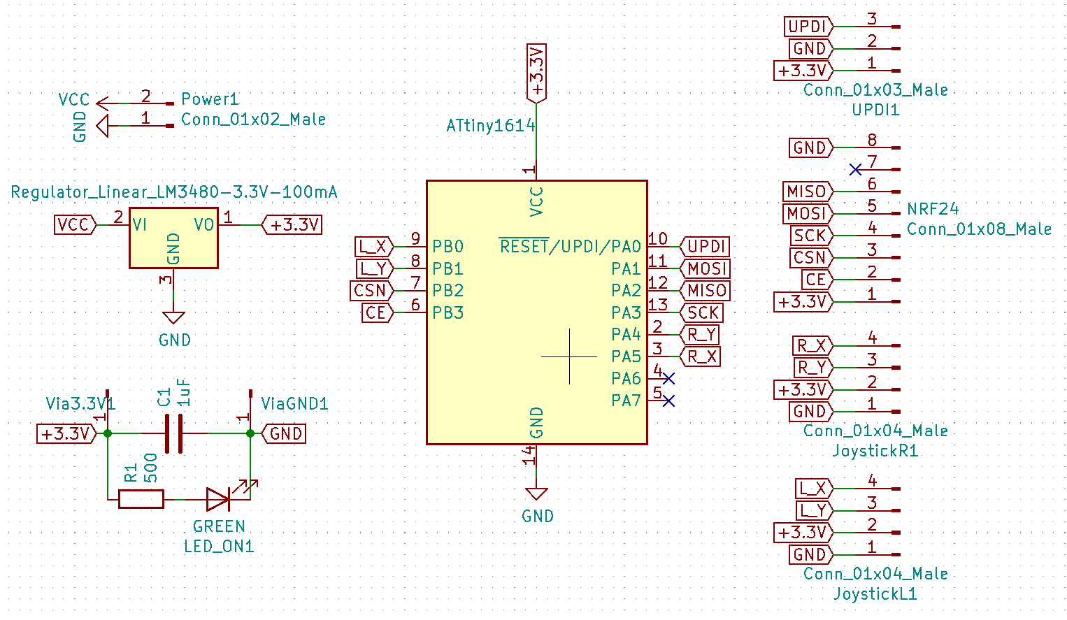
Requirements, considerations and component selection:
I used a nRF24 module for communication (which is not really part of my board itself, but I needed to determine it beforehand 😅); then arrangement of the pin headers for the this module is made is such a way I can plug it in without using cables).
Since the nRF24 module works at 3.3V, then I needed a 3.3V voltage regulator, but ☝🏼 also the Joysticks work at 3.3-5V, aaand also the ATtiny1614 can work at that voltage. I mention it because my first thought was using also a 5V regulator for the microcontroller.
I used the ATtiny1614 microcontroller cause it has the necessary pins for this application.
UPDI connection for programming, and pin headers for Power where I plan connecting 1S Lipo battery (~3.7V).
1uF capacitor for voltage stabilization.
Also as I have made on me previous boards, I added a LED to indicate when it’s connected.
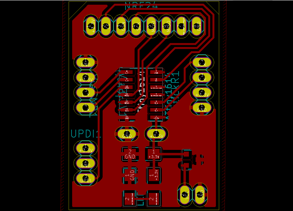
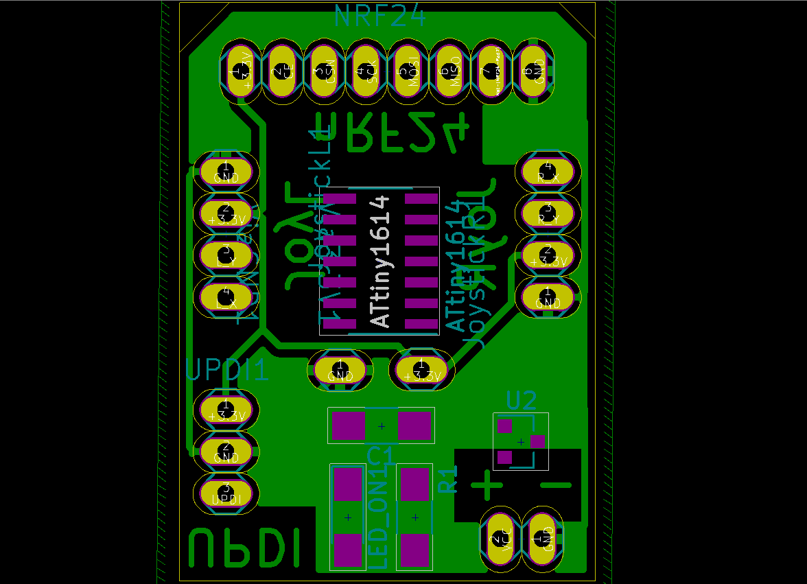
I have used TH pin headers to connect both sides of the boards, as a solution to not having rivets on hand.
I have used the footprint of TH pin headers for the Joysticks, but the idea was just soldering short cables so I get more freedom to arrange them.
/* Made by Jefferson Sandoval for the Embedded Networking and Communications assignment * during the FabAcademy2021 * * This code was made for testing my board for a remote control for my final project which is an * Omni-directional three-wheeler. * * Uploaded to my board which, using a nRF24 module and two joysticks, serves as transmitter * sending data to an Arduino UNO board. * * Documentation: * http://fabacademy.org/2021/labs/kamplintfort/students/jefferson-sandoval/assignments/week14/ *///Libraries for Communication part (nRF24)#include<SPI.h>#include<nRF24L01.h>#include<RF24.h>RF24radio(4,5);//Create radio object with and CE & CSN pinsconstbyteaddress[6]="00111";//Transmitter communication addressvoidsetup(){radio.begin();//Initialize radio objectradio.setPALevel(RF24_PA_LOW);//Set radio rangeradio.openWritingPipe(address);//Set address to receiverradio.stopListening();//Set module as transmitter}voidloop(){intValues[3];////Declare variable for data to send//Read values from Joysticks and convert them to percentage.//I used 200 cause the joystick can rotate only 50% on any direction.Values[0]=map(analogRead(0),0,1023,-200,200);//Left and Right movement from Joystick_1Values[1]=map(analogRead(1),0,1023,-200,200);//Forward and Backward movement from Joystick_1Values[2]=map(analogRead(7),0,1023,-200,200);//Rotation movement from Joystick_2radio.write(&Values,sizeof(Values));//Send array of Values to Receiverdelay(300);//Send values every 0.3 seconds}
/* Made by Jefferson Sandoval for the Embedded Networking and Communications assignment * during the FabAcademy2021 * * This code was made for testing my board for a remote control for my final project which is an * Omni-directional three-wheeler. * * Uploaded to an Arduino UNO board which, using a nRF24 module, serves as receiver reading data * from another board with 2 joysticks as input. After reading the received values, it prints on * Serial monitor a message that indicates the corresponding vehicle movements. * * Documentation: * http://fabacademy.org/2021/labs/kamplintfort/students/jefferson-sandoval/assignments/week14/ *///Libraries for Communication part (nRF24)#include<SPI.h>#include<nRF24L01.h>#include<RF24.h>RF24radio(7,8);//Create radio object with and CE & CSN pinsconstbyteaddress[6]="00111";//Receiver Communication addressvoidsetup(){Serial.begin(9600);//Begin Serial communication at 9600 baudsradio.begin();//Initialize radio objectradio.setPALevel(RF24_PA_LOW);//Set radio rangeradio.openReadingPipe(0,address);//Set address to transmitterradio.startListening();//Set module as receiver}voidloop(){intValues[3];//Declare variable for data to receiveif(radio.available()){radio.read(&Values,sizeof(Values));//Read array of Values from Transmitter//Print on Serial monitor a message according to the direction of movement of the joysticksif(Values[0]>=15){Serial.println("Forward");}if(Values[0]<=-15){Serial.println("Backward");}if(Values[1]>=15){Serial.println("Right");}if(Values[1]<=-15){Serial.println("Left");}if(Values[2]>=15){Serial.println("C-CW rotation");}if(Values[2]<=-15){Serial.println("CW rotation");}}delay(300);//Read values every 0.3 seconds}
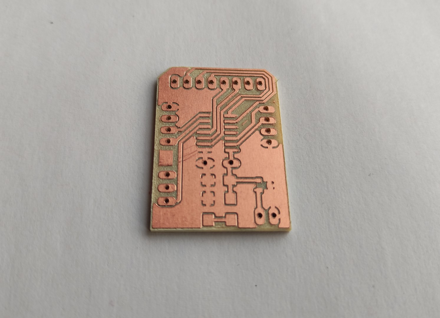
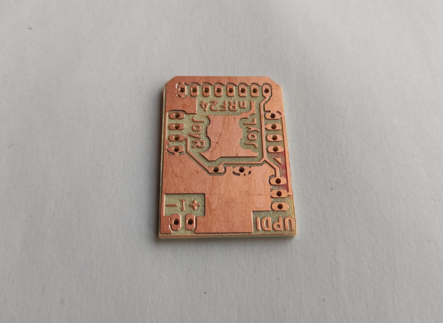
During the testing of this board I found out that when using the Vcc and GND of the UPDI connection, the voltage regulator smokes, so I powered it up from the Power pins and used a jumper cable for the UPDI. This left me two important considerations that I will take for the official board for the final project:
Take as Input for the [3.3V] voltage regulator the Vcc from the UPDI.
Since I’ll use the Vcc and GND from the UPDI connection and use them for the battery, I will delete the current Power pins which will also save some space on the bottom of the board (taking in count the female pins I have to use to connect the battery).
Also for future applications, If it’s needed a separated power supply (for example 12V), the voltage regulator should contain two pin headers to close the circuit when connecting the external supply and open it when programming.