- Project development
Getting the idea
This section has been pre-worked during my Principles and practices assignment.
First of all, I brainstormed for inspiration by looking for FabAcademy final projects from previous years and watching electronics project videos on YouTube, also thought about blending it with one of the projects whose development I am part of as part of my job at the Hochschule Rhein Waal; these were the possible ideas to follow:
- Coin Sorting Machine.
- Assistant for blind people.
- Wheeled robot.
- Soil sampler module.
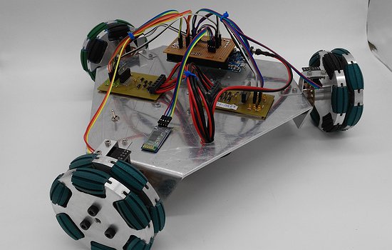
Because of the wide applicability and possible future improvements, I chose making an Omni-directional three-wheeled robot, of which I made one during the Fundamentals of digital fabrication 2020 course; but since I wasn’t completely satisfied with the results, I have made an improved version of this previous work based on my Outlooks of it.
I’m also interested on learning ROS and, even when there are devices available for it on the internet, I think that using a vehicle made by me is going to help me more to understand and it could also produce a greater appreciation to it.
Sketching the idea
This section has been pre-worked during my Principles and practices assignment.
Note: The following sketches were drawn thinking of using W1 as a front, but during development when I wanted to add a temperature sensor I realized that it is better to place the front in the middle of two wheels, then the final project is working with the front between W1 and W2.
Project idea:
- The front of the vehicle is on W1 and is controlled by radio transceivers.

Omniwheel:
- An omni-wheel is made up of two parts: a main wheel (driven by its respective motor) and smaller rollers (driven not by its motor, but the rotation of the other omniwheels), which gives it the dual axis movement capacity:

- Wheels rotation logic according to the direction of movement of the vehicle:

Development
This section has been pre-worked during my Applications and Implications assignment.
What does it do?
The robot moves with three axes of freedom:
- X _ Forward and Back ward.
- Y _ Sideway.
- Rotation _ Clockwise and CounterClockWise.
The movements are controlled by a remote control using nRF24 radio transceivers for the communication, and Joysticks as inputs that indicate direction and speed.
Who’s done what beforehand?
I have found a few similar projects in the Archive of FabAcademy, but all the ones I found were four-wheelers, and mine one is a three-wheeler (which doesn’t seem to be super relevant, but it’s different when it comes to the mechanical and coding part).
I found a three-wheeled “Robot Omnidirecional” documented in the FabLab U. de Chile page, that although it is not a FabAcademy project, it’s anyway open source and made with the basic tools in a FabLab:
I leave the auto-translated description of the project (originally in Spanish):
The robot is capable of moving with three independent degrees of freedom, one corresponding to the forward-backward movement, another to the left-right movement and another corresponding to the rotations. The motor control is done using an Arduino board that receives remote instructions from the application developed for Android.
The project was developed for the Robotics and Mechatronics Project Workshop."
I will be making me own boards, make a physical remote instead of an app and use a distance sensor for collision avoidance (in addition to other things, like the materials for the frame, design, and so on).
What did you design?
I designed:
- Main body if the Robot (Electronics + case).
- OmniWheels.
- Remote control (Electronics + case).
What materials and components were used?
Robot:
- Frame: 3mm acrylic.
- Microcontroller on board: ATtiny3216.
- Motors: JGA25-370.
- Motor drivers: TB6612FNG.
- Distance sensor: GP2Y0A21YK infrared distance sensor.
- Communication: nRF24.
- Power: 3S lipo battery (~11.1V).
- Wheels: PLA + TPU, and 3mm rods.
Remote control:
- Frame: 3mm acrylic.
- Microcontroller on board: ATtiny1614.
- Communication: nRF24.
- Grove - Thumb joysticks.
- Power: UR18650 single cell lipo battery.
How much did they cost?
The plan was to make the project cost less than $100 but since it’s a development project and it was needed to 3D print some tests and so on, the cost has increased to $115.
Where did they come from?
I have bought some components on Amazon and Digikey, and others I have obtained from the FabLab (whose main seller is Digikey).
Commercial components:
- nRF24 modules.
- Thumb joysticks.
- Batteries.
- Motor drivers.
What parts and systems were made?
- Frames for robot and remote control.
- Microcontroller boards for robot and remote control.
- Omniwheels.
What processes were used?
- Computer aided design, 2D and 3D: Wheels and frames.
- Laser cutting: Frames.
- 3D printing: Wheels.
- Electronics design: Boards for remote control and Robot.
- Input devices: Joysticks.
- Output devices: Motors.
- Embedded Communication: nRF24 transceivers.
What questions were answered?
-
Q: Is the acrylic a good material for the robot?
A: It has been a good material so far.
- It satisfies my intention of being able to show the inside.
- I have not had any collision accident, so I don’t know how resistant it is. Although we already know that, in this cases, acrylic is more a beautiful material than resistant… also we know that it also depends on the structure of the body. -
Q: Will the design+materials of the wheels be good enough to work indoor and outdoor?
A: Yes, it was. It’s worth to mention that my outdoor environment was also very flat (but well, it’s not big enough to be driven over very rough roads) -
Q: Will the torque of que motors (1.4Kg*cm each) be enough to work on no-flat surfaces (which are inevitable in outdoor environments)?
A: Yes! As I said before, outdoor environment was also very flat, it has only a lot of small rocks. -
Q: Since I plan controlling the robot using ROS after the FabAcademy… Is my project going to be completely and easily adaptable for that purpose? Will I need to change/add something else?
A: This is a question that I will clear when I start working on the ROS application.
What worked? What didn’t?
- Everything I made is currently working.
- There’s one thing that I that I have not been able to finish yet: the collision avoidance part. I had an accident with the original motor drivers for the robot. I was using the TB6612FNG, but they burned during a test then I made a designed a new board with the L298N (which needs diodes, contrary to the others), so I spent my time on that new design, tests and adjusting the code for the new drivers.
I share a video testing the performance of the system at maximum speed (255):
- A quick comment… Eventually, I realized that the nRF24 radio transceiver modules are not really the best in this case. I lose connection from ~2 meters, a better option would be a radio transceiver wit external antenna or ☝🏼 moving the electronics to the outside so the case doesn’t block the signal.
What happened when?
For my time management, at the beginning, I tried to make it very formal and clean with a digital schedule that I into small tasks that I made during the assignments, whose deadlines would be the end of the week:
| Week | Task |
|---|---|
| Principles and practices | Propose and sketch the final project idea. |
| Computer Aided design | Draft Model of the final project. |
| Input devices | I made a first test with the Joysticks that I used later for the remote control. |
| Output devices | I made a motor controller board to test with the L298N drivers that I used later for the robot. |
| Embedded Networking and Communications | I the board Version#1 of the remote control the remote control using nRF24 modules. |
| Applications and Implications week | - I cut the Frames for the robot and remote control. - I made the final version of the remote control board. |
| Invention, Intellectual Property and Business Models | -I made a draft of the Slide and video. - I stablished the license for my project. - I printed the OmniWheels |
| Project Development | I made the board for the robot. |
Later I found that this method doesn’t really work for me, it’s a bit tedious and I don’t really like digital ways to manage the development of a project (unless it’s a group project, but still for my very personal tasks I wouldn’t do it digitally).
I tried an old school way. I have used a printed calendar that I keep on my desk so I can check it every time:
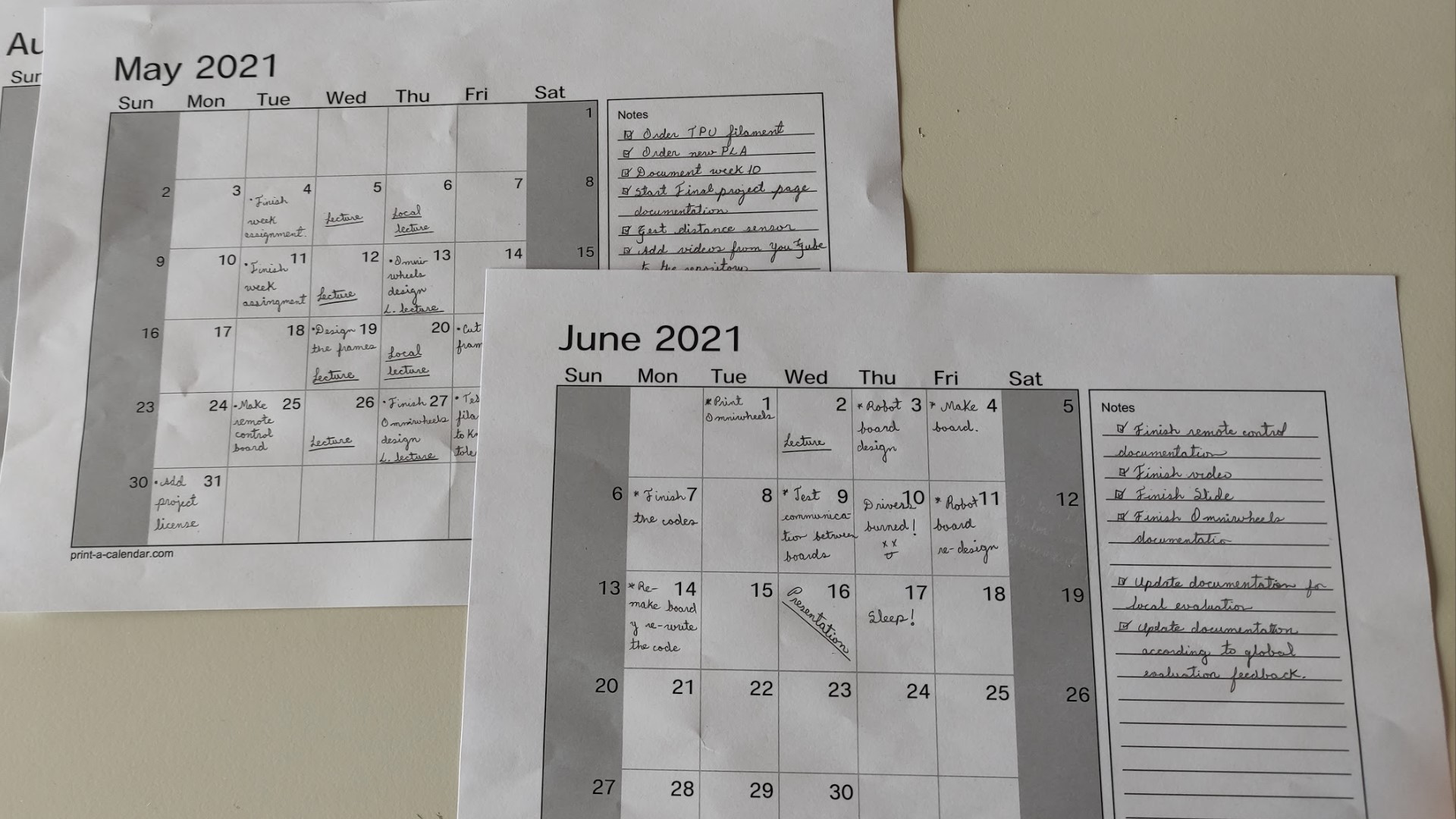
I have made it using print-a-calendar.com.
- I wrote each assignment on its deadline.
- I also made some extra notes and reminders for every task.
This method really helped me a lot cause every time I was aware of the whole current stage and the missing tasks. I found a paper + a pencil very easy and simple to make notes anytime, regardless of whether I am using the computer or not.
How was it evaluated?
- It should be able to move with 3 degrees of freedom.
- It must be controlled by its remote control.