11. Input devices
- Probe an input device(s)’s analog and digital signals. Document your work (in a group or individually):
Group assignment page: here.
My individual part:
- I have probed the analog signal of a Joystick.
- I have probed the digital signal of a Sonar sensor.
- Measure something: add a sensor to a microcontroller board that you have designed and read it:
Since for my final project, the only inputs I need are two joysticks and a distance sensor, then I worked on learning how to program an ATtiny microcontroller, using the board that I have made during the Electronics design assignment.
Board used
For this assignment I programmed MyMiniBoard_X14, a board I made during the Electronics design assignment.
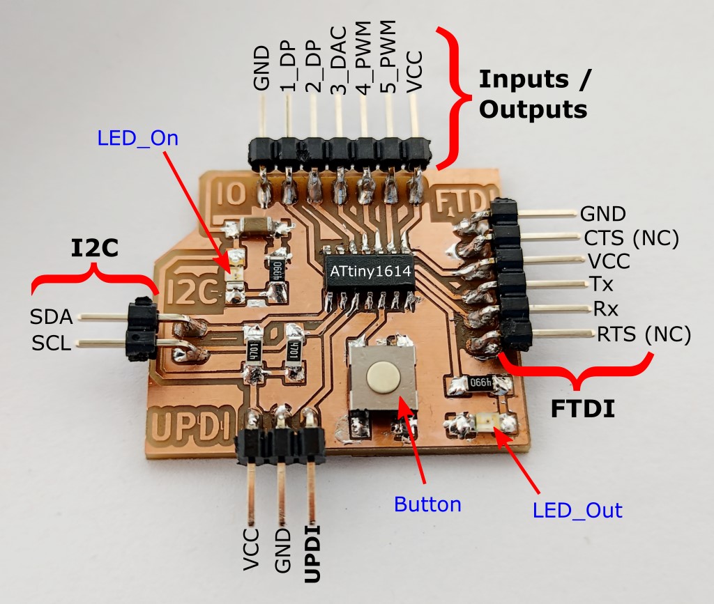
ATtinyX14 pinout
For this practice I used the ATtiny1614 from the ATtinyX14 series, but since they have the same pinout, any of them can be used on this board.

Joystick
Component: Grove - Thumb Joystick v1.1
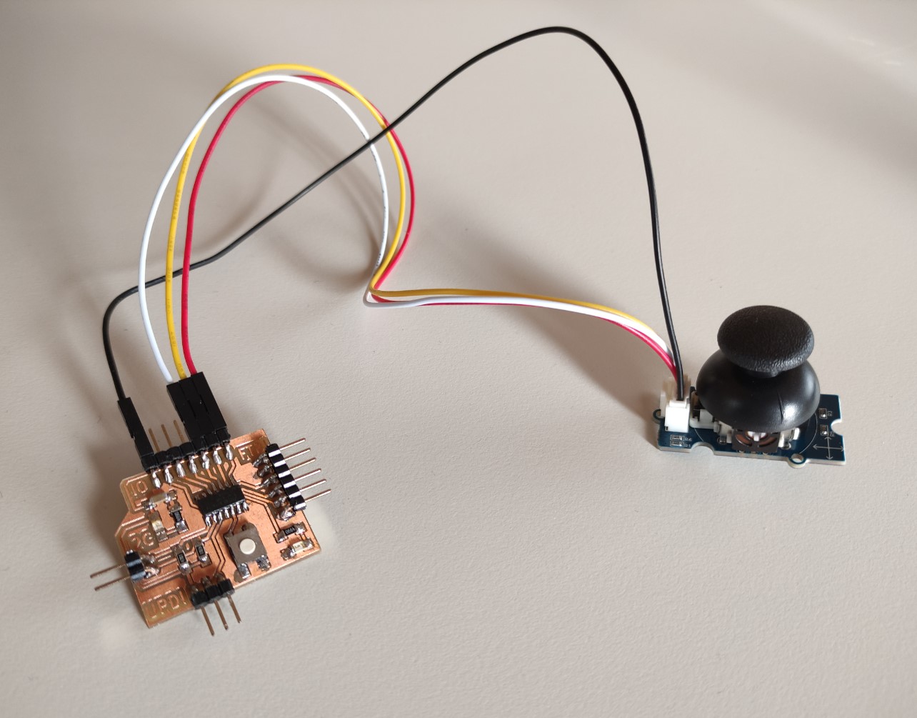
Pin configuration:
| Sensor | Board | ATtiny1614 |
|---|---|---|
| Vcc | 5V | Vcc |
| GND | GND | GND |
| x | Pin 5 | 0~ |
| y | Pin 4 | 1~ |
Code
1 2 3 4 5 6 7 8 9 10 11 12 13 14 15 16 17 18 19 20 21 22 23 24 25 26 27 28 29 30 31 32 33 34 35 36 | |
Performance
Probing the Joystick
I did the test connecting the X pin to Channel A:
Description:
- What we can see on the oscilloscope is the analog signal of one of the potentiometers of the Joystick.
- The negative and positive values that we can see in the signal is what I used in the code to know the direction and percentage of pressure.
Sonar sensor
Component: HC-SR04
Pin configuration:
| Sensor | Board | ATtiny1614 |
|---|---|---|
| Vcc | 5V | Vcc |
| GND | GND | GND |
| Trig | Pin 5 | 0~ |
| Echo | Pin 4 | 1~ |
Code
1 2 3 4 5 6 7 8 9 10 11 12 13 14 15 16 17 18 19 20 21 22 23 24 25 26 27 28 29 30 31 32 33 34 35 36 37 38 39 40 41 42 | |
Performance
Probing the Sonar
Before doing the test I made a quick research cause I didn’t really know what and how I was supposed to probe 😅, then I found a good explanation of the sonar sensors:
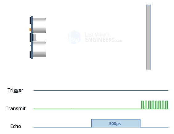
Image taken from Last Minute Engineers
In this case I wanted to watch and compare the behavior of Trigger and Echo sensor.
I made the test connecting the Echo pin to Channel A (in yellow), and the Trigger pin to Channel B (in green):
Description:
According to the code uploaded to the board:
- The Trigger sensor produces the 10 µS pulse (the green signal in the oscilloscope) every 100 microseconds.
- The Echo sensor uses the width of the received pulse (the yellow signal in the oscilloscope) to then calculate the distance to the reflected object (my hand in this case).
Files
- JoystickCode.ino
- UltrasonicCode.ino