Final project
About my project
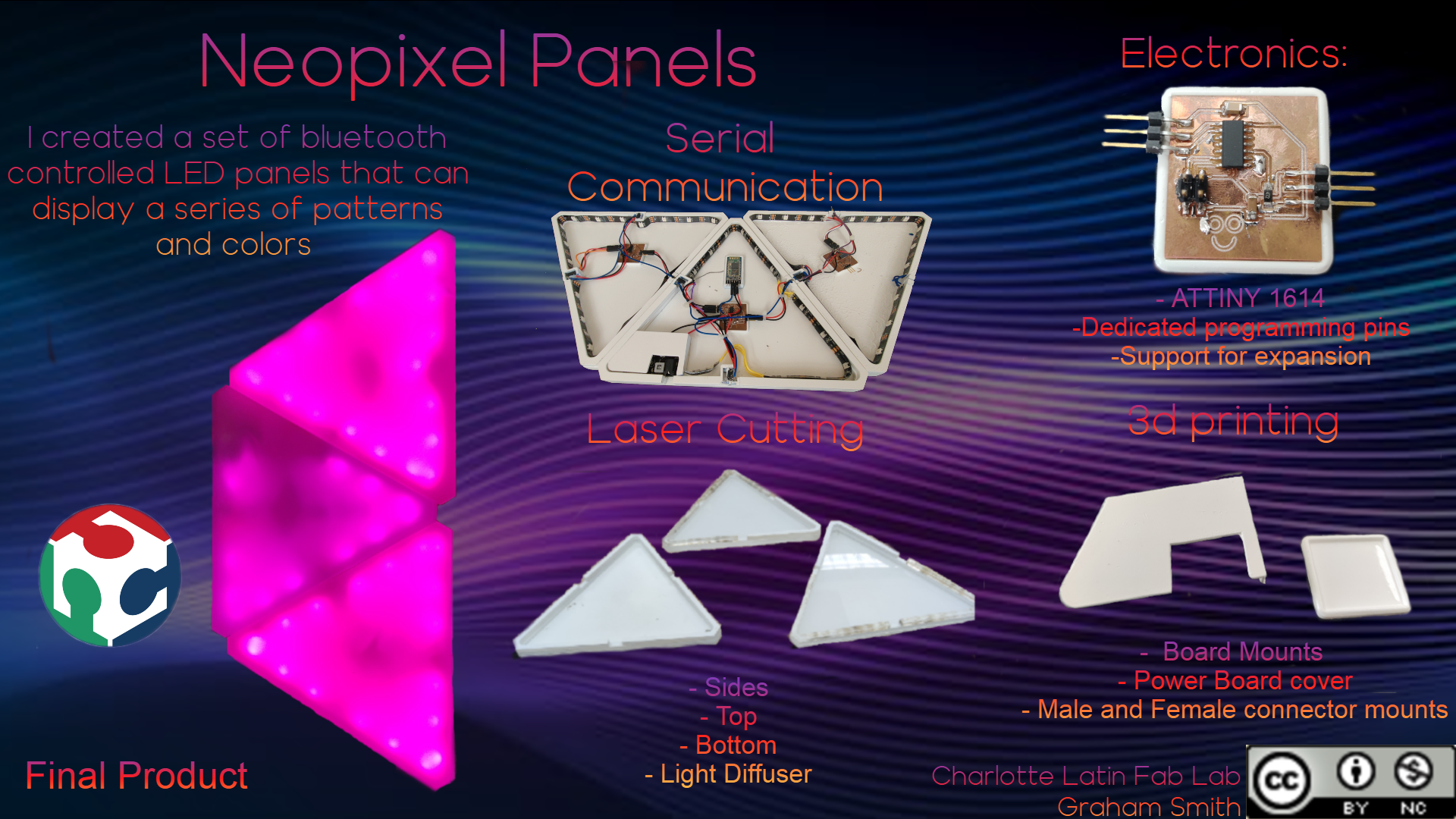
For my final project, I have decided to make NanoLeafs. NanoLeafs are LED panels that you can hang on your wall or ceiling to create a cool, customizable LED affect that can light up your room. Nanoleafs have been around for a few years now but becuase of their expensive price, not everyone has been able to access them. My main goal for this project is to create a guide so that any other engineer can replicate them on a budget. I plan on not only documenting on my site, but also on etsy or thingverse. This will allow more people to see and hopefully try out my project.
Drawings
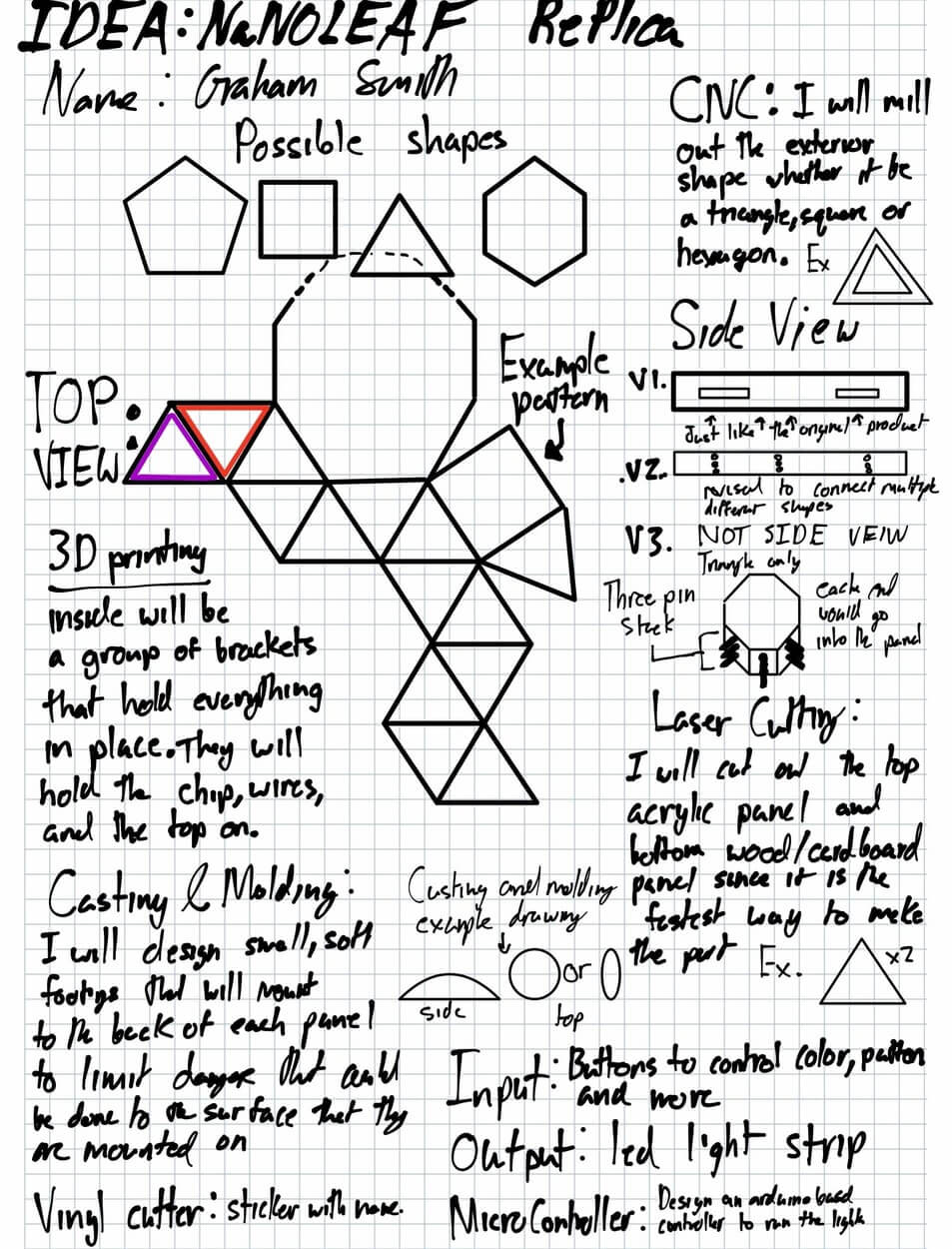
Our week one assignment was to think through our idea. I breifly summarized what each machine would do for my project but will elaborate much more on the reasons below the image.
License

Creative Commons Attribution-NonCommercial 4.0 International License
How is it going to be made?
As part of my goal for this project, I want to make it as simple and cheap as possible but still have the functionality of the original project. I will be using the CNC machine to cut out the triangle outline of the frame using a soft material like wood. Then I will sand and either stain or paint it a dark color. I will then use the laser cutter to cut out the two triangular panels per panel out of clear and black acrylic. I will then frost the top, clear panel to diffuse the lights inside. 3D printing and molding will be nessecary on the inside to hold the custom PCB in place. finally i will use custom connectors to hold each NanoLeaf together.
Rendering

Parts
| Machine | Part | Notes |
|---|---|---|
| 3D Printer | Interior Mounts | The mounts will help hold wires and the board in place |
| CNC Machine | Exterior Frame | Made of wood, will be stained/painted in a dark color |
| Laser Cutter | Acrylic Top and Bottom | Top layer will be frosted. Bottom will be made black acrylic |
| Vinyl Cutter | Tag | It will mark which panel is the ‘hub’ and which are add-ons |
| Output | LED strip | The strips will line the inside of the CNC material |
| Input | Buttons | Buttons will control brightness, color, and patterns |
| Molding & Casting | Pads | The pads will go on the back of each panel and protect it from rubbing on the surface that it is mounted on |
| Micro Controller | Arduino Based Board | The board will be the brain and control each part of the project |
Project Idea Development
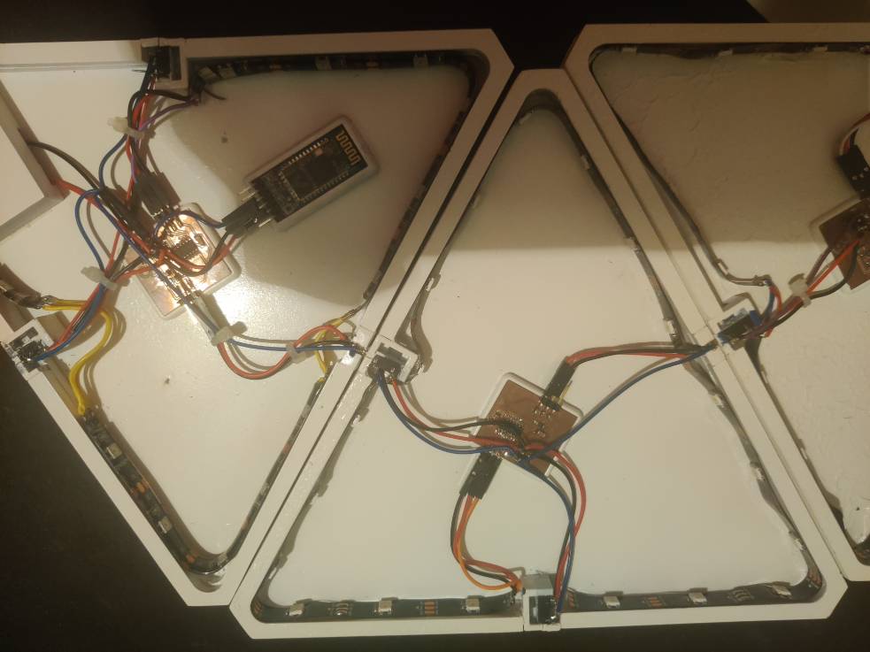
Over the course of this last week (March 16), I have spent a tremendous amount of time think through and working on my project. I started off the week by think of the sensors that I want to use and what I wanted my project to do. What I have ultimately decided is that I want to control the on and off of my project by clapping. For this I am going to need a sound sensor. For the sake of rapid prototyping, I ordered this part along with some other parts. I plan on first developing it all on an arduino with pre made components before I break it all down into custom PCBs that I will mill. The next part of my project that I really had to think through was how I was going to connect my panels. There were two ways that I thought I could do it. The first was using pins placed in specfic location along the side of my project but after careful thought, I realized that I was going to need to do something better. Then I though of using a headphone jack. After some research I deteremined that I could use a headphone jack placed in the center on each panel. This would provide an easy way of connecting the panels and allow for me to have two extra ports that I could run to each panel. I also wanted to make my panels bluetooth controlled. I already had a bluetooth HC-05 chip on hand and was able ot reference guides on instructables and the arduino forums to get it working.
![]()
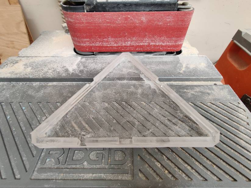
Other than just thinking through my project, I actually started creating different aspects of it. I used my labs laser cutter to quickly prototype my final project. I then took some extra LED strip hanging around to test how the light would react with the acrylic that I was using. I found out that it would be nessecary for me to adjust the opacity of the acrylis in some way. In my electrical engineering class last semester, we used this spray frosting for glass and acrylic. While it didnt work well for the project that we were doing, I was able to use it in this project. I quickly used it to cover have of the acrylic before I used the LED strip to test how it turned out.
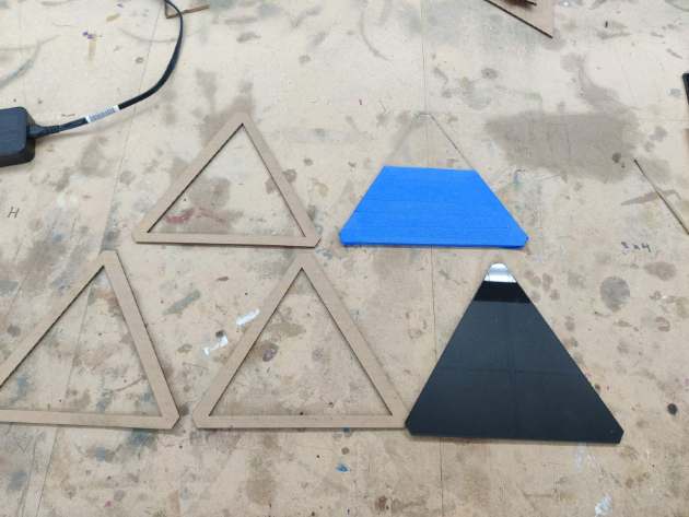
Unfortunately, it didnt turn out how I wanted so I tried using a sheet of paper. Seeing that it looked like it would work, I used our labs laser cutter on the lowest power and highest speed to cut out the paper in the same shape as the acrylic. I then put the two together and saw the results I wanted.
After I tested with different ways to diffuse the light, I tried with different spacing for the LED strip. The first and orignal LED strip I used was spaced out pretty far so I found another strip that was closer together to see how it would work. While I did like how it turned out, I felt that the first one looked better with the current situation for diffusing that I had. In the end I ended up sticking with the strip that was spaced far apart. When I make my custom board, I plan on integrating the LEDS into my circuit.
Final Project Assembly
Step 1 - The Electronics
The Electronics for this project were heavily based off of what I made in week 14 for networking. Back in week 14, I started to think through what the boards would need to do for me. Originally I was going to have the bluetooth hc5 board connect to a master board which would then connect to the node but after carefull consideration, I decided otherwise. Now I am planning on eliminating the master board and instead running everything on multiple node boards. During testing of this I found that it would work and also helped me keep timing consitent between all strips. I also elimated the idea of adding microphone so those pins were no longer needed.
Board Design
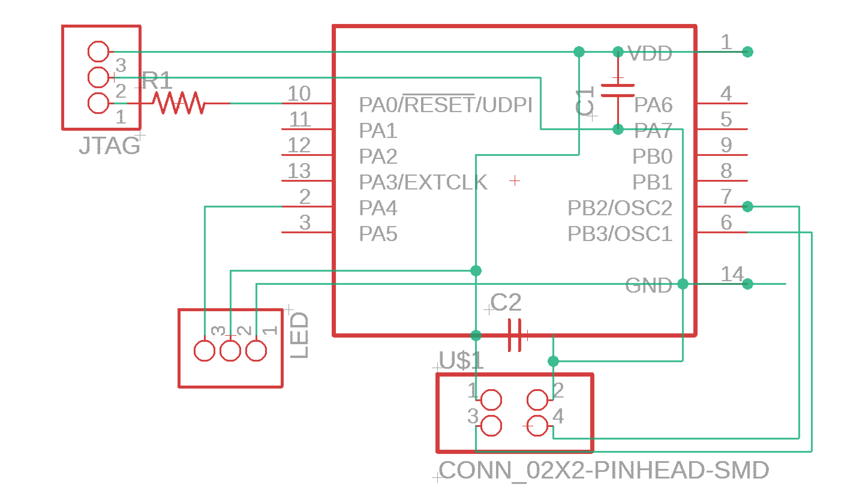
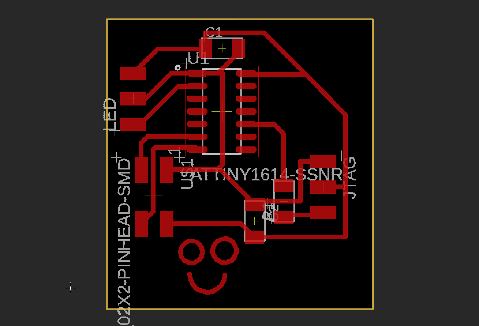
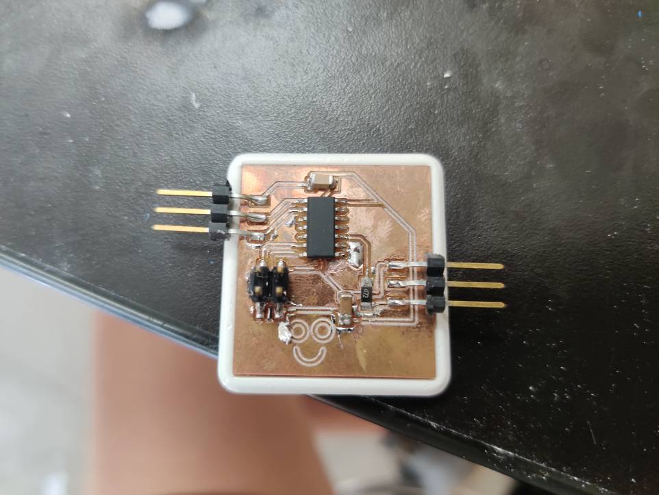
Designing my boards for this project was one of my favorite parts of my project. It was also the part that I was most concenred about. I wanted to make sure that I got it right the first time. For my main board, which was a really similar design to the node boards, I used a at tiny 1614 chip that connected to and powered the bluetooth chip and a strand of leds. The reason I chose the 1614 was because I was going to need more than just 1 tx and rx pin on the 412. I also hadnt decided yet to drop the idea of adding a microphone to my project. Other than the 13 pins that would control stuff like the LEDS and bluetooth chip, I also added a 2x2 pin setup to power and control the node boards. I also added a 1uf capacitor to help with smoothing and a 4.7k ohm resistor for JTAG.UPDI. while my friend and fellow fab student jack hollingsworth may refute this, I believe that it is key to include this resisotr. The node board was very similar to the main board except that it had far less pins and used a 412 chip. Over the course of Fab Academy, I have used the 412 countless times and it has become one of my favorites to use. For such a small package it is so powerful and can serve in so many applications. For the node board I included a built in RGB led for testing. I decided to keep this led functioning after I completely assembled my project later on. I also included the same setup for JtAG.UPDI and control pins. After I finished all these boards, I milled and tested each one. They all worked so I was ready to resume my electronics.
 Also during testing, I reconized my need for a seperate power supply. I found a board in my lab that takes 12v in and produces multiple 5 and 3.3v power sources. Another integral part of the electronic system was the tabs that connected each panel together. I had a few Ideas for this system. The first and most simple idea was using male and female jumper pins. This idea seemed to simple for me so instead so I then started to thing about using something similar to an auxilary port. This would give me everything that I would need to communicate between boards but wouldnt allow for a completely modular system. I decided that I would see what the original panels did and try to improve on the system. The offical Nanoleaf used tabs that clip into each panels. These are a good solution but out easy to break if a panel were to fall off a wall. I decided that I would use male headers that would rub up against a solid copper PCB. I thought this system created durabilty and also served its purpose well but the tabs werent making solid connection so I went back to the idea of the auxilary ports. The easiest part of the electronic system was adding the Neopixels themselves. After spending all this time working on the baords, I was ready to test. Unfortunately, they didnt work as I planned but they did work. After two days of breaking down the code to see why I couldnt work with more than 7 leds and why I couldnt use Serial, I discovered that the tiny neopixel library must have had a flaw. I talked to one of my instructors who was an electrical engineer and he too agreed that I would have to use a different chip. From a past week, I already had a board that could worked with a 1614 chip and neopixels. I tried the code on this board and it worked so I started to design a better 1614 board that I could use. Everything remained the same from the 412 board except the chip. I made a few of these and was ready to work on improving the very basic code that I had been testing with.
Step 2 - Code
The code for my project was by far the hardest part of my final project. I never had tried to make my own custom code for a big project like this before so this was a big learning experience. Before I started to write the code, I thought of what I wanted to code to do and how I wanted to interact with it. I wrote this all down on a whiteboard and also wrote down the order that I would take to slowly reach my final code
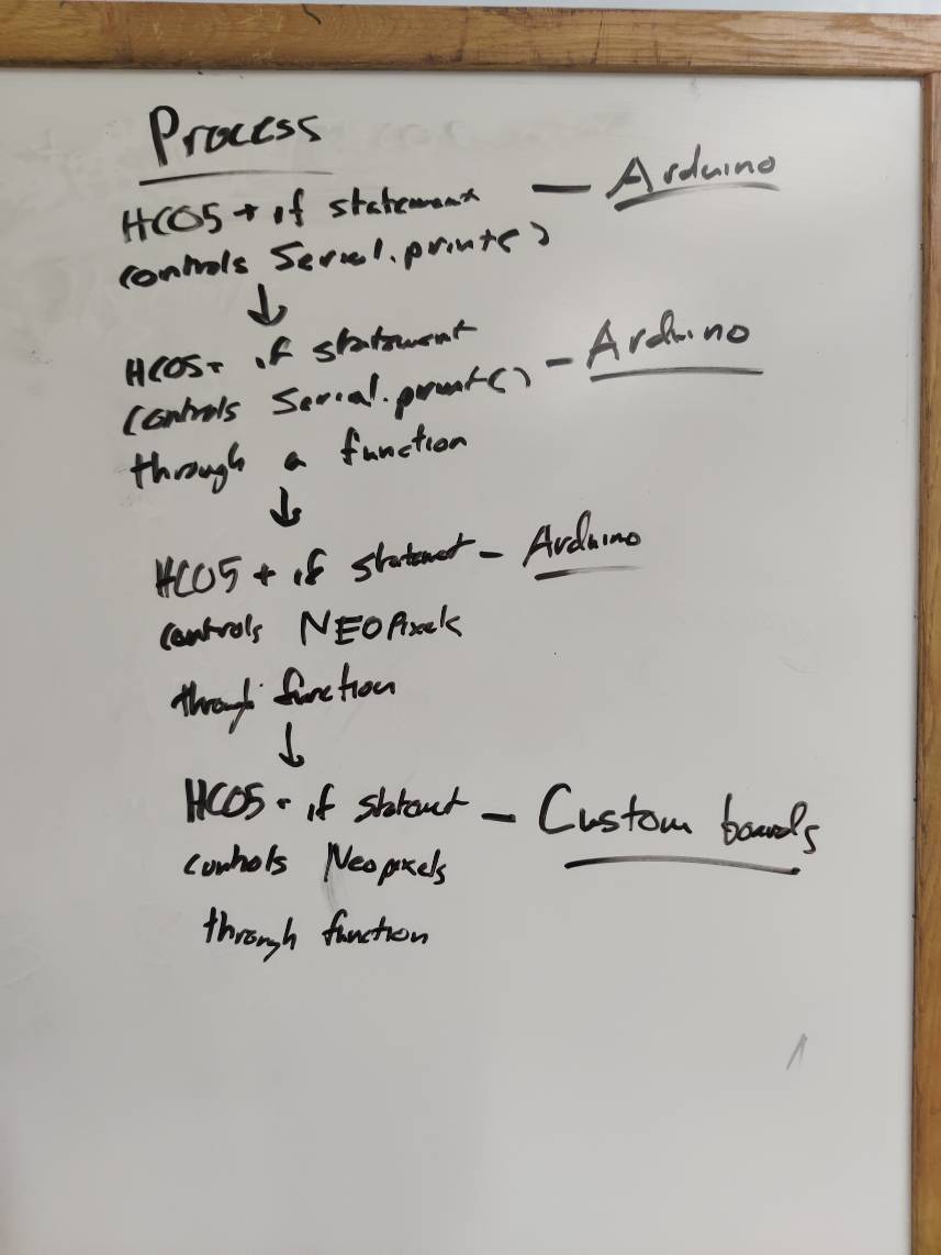
After I came up with the flow chart, I started to work on the different steps that I felt like would be the best for development of my final code. For the first step, I wanted to use an arduino and the bluetooth chip to control a series of if statements that would print something back over the bluetooth serial. The first step for this code was initialize serial and then I followed it up by reading and assigning the serial values. Then I compared those values to a number or letter like 1 which would determine if it printed.
void setup(){
  Serial.begin(9600);

}

void loop(){

  if (Serial.available() >0){
    char indata = Serial.read();

    if (indata == 'b' ){
    Serial.println("printing 1");

    }


    else if (indata == 'a'  ){
     Serial.println("printing 2");


    }

    else if (indata == '3' ){
     Serial.println("printing 3");
  }
 }
}
The next iteration of this code was to use fuctions to write into serial instead of directly under the if statement. I did this so that I could make sure I was able to call the functions that I would need for the Neopixels. The code remained the same for the setup and then in the loop I added an additional FunctionName();. I replaced the function name with task1 or task2 depending on what function I wanted it to run. Outside of the loop, I created my functions to print something very similar to what it was printing in void setup. Below is that code.
void setup(){
  Serial.begin(9600);

}

void loop(){

  if (Serial.available() >0){
    char indata = Serial.read();

    if (indata == 'b' ){
    Serial.println("printing 1");
    task1();
    delay(3000);
    }


    else if (indata == 'a'  ){
     Serial.println("printing 2");
     task2();
     delay(3000);
    }

    else if (indata == '3' ){
     Serial.println("printing 3");
     task3();
     delay(3000);


  }
 }
}
void task1(){
  Serial.println("printing task 1");
  }
}
void task2(){
  Serial.println("printing task 2");
}

void task3(){
  Serial.println("printing task 3");
}
The third version of this code controlled the Neopixel functions that I copied in from the Adafruit Neopixel strandtest. I wanted test it on an arduino first before I started to use a custom board just so that I could make sure the code was the issue if one should arise. I reference existing code from the example section of the adafruit neopixel library to add everything that I thought I would need. After I added what I thought would work, I tested it and it didnt. The issue ended up being a missing } which I easily fixed.
#define pix 16

#include <Adafruit_NeoPixel.h>
Adafruit_NeoPixel leds(pix, 0, NEO_GRB + NEO_KHZ800);

void setup(){
  Serial.begin(9600);
  pixels.begin();
  pixels.show();
  pinMode(4, OUTPUT);
  Serial.println("test);
}

void loop(){

  for(int i=0; i<pix; i++) {
  pixels.setPixelColor(i,0, 150, 0);
  pixels.show();
  }
  delay(1);

  for(int i=0; i<pix; i++) {
  pixels.setPixelColor(i,0, 150, 0);
  pixels.show();
  }
  delay(1000);

  for(int i=0; i<pix; i++) {
  pixels.setPixelColor(i,150, 0, 150);
  pixels.show();
  }
  delay(1);
  for(int i=0; i<pix; i++) {
  pixels.setPixelColor(i,150, 0, 150);
  pixels.show();
  }
  delay(1000);


  if (Serial.available() >0){
    char indata = Serial.read();
    if (indata == 'a' ){
    Serial.println("printing 1"); //Blue
    task1();
    delay(5000);
    }


    else if (indata == 'b'  ){
     Serial.println("printing 2"); // Red
     task2();
     delay(5000);
    }

    else if (indata == '3' ){
     Serial.println("printing 3"); //rainbow
     task3();
     delay(5000);


 }
}
}
void task1(){
  Serial.println("printing task 1");

  for(int i=0; i<pix; i++) {
 pixels.setPixelColor(i, pixels.Color(0, 0, 150));
 pixels.show();
  }
  delay(1);
  for(int i=0; i<pix; i++) {
 pixels.setPixelColor(i, pixels.Color(0, 0, 150));
 pixels.show();
  }
  delay(1000);

}
void task2(){
  Serial.println("printing task 2");

  for(int i=0; i<pix; i++) {
  pixels.setPixelColor(i, pixels.Color(150, 0, 0));
  pixels.show();

  }
  delay(1);
   for(int i=0; i<pix; i++) {
  pixels.setPixelColor(i, pixels.Color(150, 0, 0));
  pixels.show();

  }
  delay(1000);
}

void task3(){

  uint16_t i, j;

  for (j = 0; j < 256; j++) {
    for (i = 0; i < strip.numPixels(); i++) {
      strip.setPixelColor(i, Wheel((i + j) & 255));
    }
    strip.show();
    delay(wait);
  }

}

uint32_t Wheel(byte WheelPos) {
  WheelPos = 255 - WheelPos;
  if (WheelPos < 85) {
    return strip.Color(255 - WheelPos * 3, 0, WheelPos * 3);
  }
  if (WheelPos < 170) {
    WheelPos -= 85;
    return strip.Color(0, WheelPos * 3, 255 - WheelPos * 3);
  }
  WheelPos -= 170;
  return strip.Color(WheelPos * 3, 255 - WheelPos * 3, 0);
The 4th version of the code that I made was the same as the third except that I swapped out all the libraries and its commands for the Tiny NeoPixel library that is apart of the MegaTinyCore library. During the swapping process, I never encountered an error where the format was different since the libraries are near perfect copies of each other.
#define pix 16
#include <tinyNeoPixel.h>
tinyNeoPixel pixels = tinyNeoPixel(pix, 0   , NEO_GRB + NEO_KHZ800);

void setup(){
  Serial.begin(9600);
  pixels.begin();
  pixels.show();
  pinMode(4, OUTPUT);
  Serial.println("test");
}

void loop(){

  for(int i=0; i<pix; i++) {
  pixels.setPixelColor(i,0, 150, 0);
  pixels.show();
  }
  delay(1);

  for(int i=0; i<pix; i++) {
  pixels.setPixelColor(i,0, 150, 0);
  pixels.show();
  }
  delay(1000);

  for(int i=0; i<pix; i++) {
  pixels.setPixelColor(i,150, 0, 150);
  pixels.show();
  }
  delay(1);
  for(int i=0; i<pix; i++) {
  pixels.setPixelColor(i,150, 0, 150);
  pixels.show();
  }
  delay(1000);


  if (Serial.available() >0){
    char indata = Serial.read();
    if (indata == 'a' ){
    Serial.println("printing 1"); //Blue
    task1();
    delay(5000);
    }


    else if (indata == 'b'  ){
     Serial.println("printing 2"); // Red
     task2();
     delay(5000);
    }

    else if (indata == '3' ){
     Serial.println("printing 3"); //rainbow
     task3();
     delay(5000);


 }
}
}
void task1(){
  Serial.println("printing task 1");

  for(int i=0; i<pix; i++) {
 pixels.setPixelColor(i, pixels.Color(0, 0, 150));
 pixels.show();
  }
  delay(1);
  for(int i=0; i<pix; i++) {
 pixels.setPixelColor(i, pixels.Color(0, 0, 150));
 pixels.show();
  }
  delay(1000);

}
void task2(){
  Serial.println("printing task 2");

  for(int i=0; i<pix; i++) {
  pixels.setPixelColor(i, pixels.Color(150, 0, 0));
  pixels.show();

  }
  delay(1);
   for(int i=0; i<pix; i++) {
  pixels.setPixelColor(i, pixels.Color(150, 0, 0));
  pixels.show();

  }
  delay(1000);
}

void task3(){

  uint16_t i, j;

  for (j = 0; j < 256; j++) {
    for (i = 0; i < strip.numPixels(); i++) {
      strip.setPixelColor(i, Wheel((i + j) & 255));
    }
    strip.show();
    delay(wait);
  }

}

uint32_t Wheel(byte WheelPos) {
  WheelPos = 255 - WheelPos;
  if (WheelPos < 85) {
    return strip.Color(255 - WheelPos * 3, 0, WheelPos * 3);
  }
  if (WheelPos < 170) {
    WheelPos -= 85;
    return strip.Color(0, WheelPos * 3, 255 - WheelPos * 3);
  }
  WheelPos -= 170;
  return strip.Color(WheelPos * 3, 255 - WheelPos * 3, 0);
After I had completed all these versions of the code, I did make some minor changes to get the final version of my code.
Step 3 - Frame
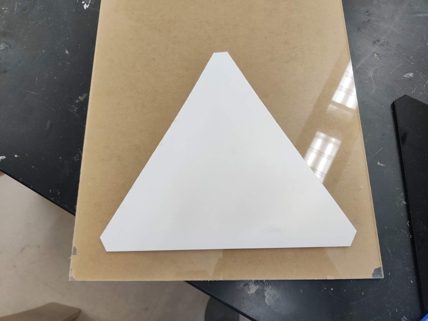
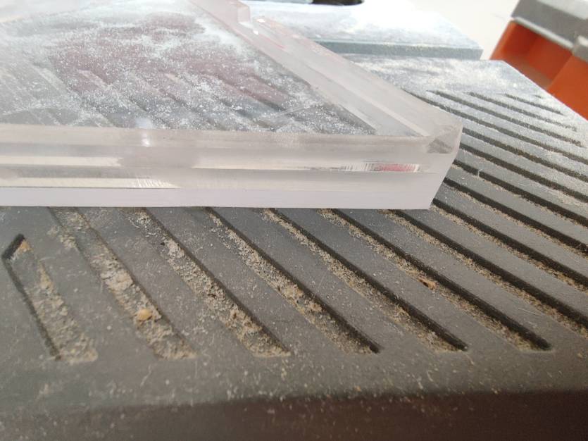
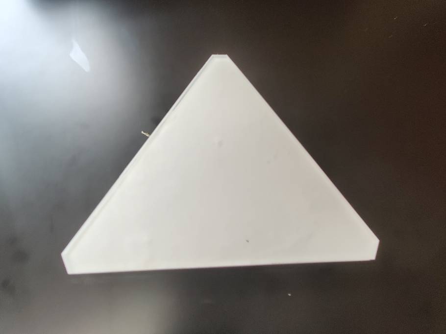
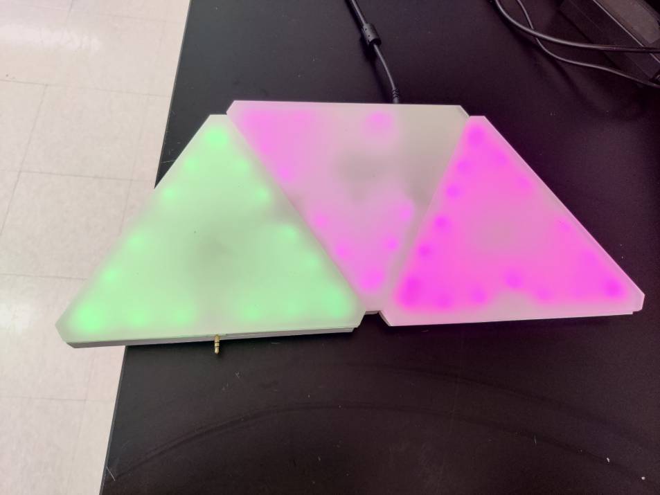
 Designing the frame and other panels was the easiest part of my final project. I started off my designing two different sizes of triangle to see which one I thought would look the best. I ended up doing the larger one that messured 203 mm on each side. This gave me enough room for all the electronics and the size looked better when on the wall. From this basic frame, I was able to start making the others parts for each panel. Each panel needs 1 base, 1 lid, l middle section, and 3 extenders. The base and lid are the same part for the design but will be painted/frosted differently for final assembly. The middle section has the same outline as the base but then has an offset that creates an open center portion. The extenders are almost the same except a small portion from the middle section is cut out. That small portion is where the tabs to connect each side are located. I designed all these parts in Fusion so that I would be able to assemble and test them. I used my labs laser cutter to cut each one out. The total cut time with the laser that I was using was just about 7 minutes per panel. I also thought about using the CNC machine but my lab didnt have the correct thickness or type of material so i stuck with acrylic. I spent at least one hour per panel sanding. I started off with a rough 120 grit sand paper to get all the lines perfectly even on each panel. After that, I went to a 220 grit paper to make it a little smoother followed by an 700 and then for the final pass a 3000 grit paper. As I worked on this, I realized that it would be possible to sand down each top of the panels instead of using a frost paint but since I had already frosted each panel, I stuck with that. After I had each panel glued together and sanded down, I was ready to paint. For all the panels, I did a light first coat of paint and then let itt dry. This layer went perfectly so I moved onto the next. The second layer I applied more paint than what I should have done and because of this combined with the hot, humid climate, the paint started to crack. While it did look cool and was fun to watch happen in real time, I needed to sand down one of the panels and try again. Later on I researched why this happens and figured out that the solvent was evaporating because of the heat. For the last coat, I made sure to do it early in the morning when the temperature was most optimal. I let each panel sit for a day before I started some final assembly.
Step 4 - Final Assembly
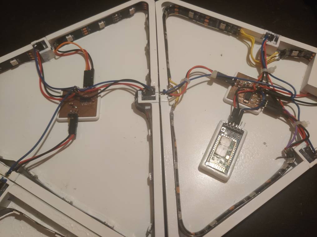
Final assembly was by far the hardest and most tedious part of my final project. The first thing that I did once I had all the components (or so I thought) was test. I started by putting in each of the 3d printed auxilary holders in. Since none of my panels were perfectly equal, I needed to sand some of these down before I could secure them in. I used gorilla glue for this part of the project because it dried fast and allowed me to keep working on parts near by instead of waiting for it to dry. After i secured those mounts, I used Nitto tape to secure down the snap fit board holder that I had designed for each board. I placed it in the middle of each of the 3 connectors so that I could make all the wiring even. After I secured the mount, I snapped each baord in. The next step was securing the power system that I was using. I decided for this section to use an existing board that we had in our lab. There were two reasons behind this. The first was our lab ran out of the regulators that I would need and second was the other connectors that I would need. This worked well because these boards are easier to access for those who hope to build there own version of my project. I used some Nitto tape again to secure that down and then I put the power supply case over that after I soldered the + and - wires onto it. For the main board that had the power supply, I also installed the mount for my HC05 bluetooth chip and the chip itself. This case was also snap fit and was connected via Nitto tape. The next part of this project was the hardest. I had to solder each wire were they needed to go. In short, each wired that was for signal was soldered to a common signal and the same goes for the ground and power. For the main panel, I plugged in the bluetooth chip and the power supply into the designated pins that I had put in my design. going forwards, I could make the design better by including a header for each in and out pin instead of having to connect them all to just one. After I did this I ran a test. It didnt work at first but that was becuase I had forgot to upload code to the new 1614 boards that I had designed. After I did this I was fortunate enough to have it all work the second time. I tested each panel to make sure that they could fit together and work. All of the ports worked except for 1 where I had accident put got gorilla glue on it. I couldnt get this off so I left it be. I also ran out of connectors so I had to leave one without. However, if I were to get more, It wouldnt take me more than 10 minutes to install and wire it. After I did all of this I started to mess around with the code. I added some rainbow functins and other cool patterns that I was able to take directly from the TinyNeopixel library example. I then started to work on an interface, I did complete it all by the time I had to present but plan to keep working on it to get it done (6.16.21).

Gallery
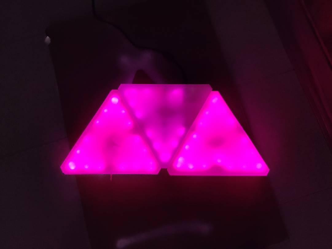
Video of it Working
For a better video showing all functions, please watch my presentation video
Issues
There were a plethera of issues that I encountered whilst I was working on my project. Most of them very easy fixs or stupid descisions but there were a few that really stood out. The first issue that I was having was the super glue was instantly bonding with the acrylic before I could line up everything. In order to combat this, I used some E6000 that took longer to cure. I also used sandpaper, which I talk about in the frame section, to make every side smooth. The second issue that I was facing was the white spray paint I was using loved to crack imediately. Upon researching this, I found that it was an issue with temperature and humidity. I tried to paint in the morning but it wasnt working. For another unknown reason, some of the panels didnt crack so I was able to get a few great looking samples. The biggest issue that I faced during this was with the code, Neopixels, and 412 chip. I was never able to run more than 7 Neopixels on one 412 while serial was running. I could run 20+ when I had serial disabled. I spent 4 days trying to prototype every possible thing with the code but never thought to check that It was an issue with serial. I still dont know the main reason this is happening becuase when I swithed to the 1614 it worked perfectly fine first try. I would assume however that it was an issue with the Tiny NeoPixel library that I was using. On top of these issues, I had many smalls ones such as parts not fitting. I was able to resolve these to and get my project done.
Simple Answers to questions that were answered in the above sections
What does it do?
My project is going to use all the skills that I have learned over the course of this class to create a set of RGB panels. Each panel will show my capabilities of 2d and 3d design, board design, and overall system integration.
Who’s done what beforehand?
Before undertaking this project, I did my research. Many people have created something similar to me in the past but the driving force behind mine was getting more out of it for less money. The actual product cost alot and even replicas that are out cost alot. They also use proprietory boards. What I am able to do is use my skills to create them for less and add more to them. Originally I planned on adding a plethera of sensors but didnt get to them. But becuase my designs are completely open source, Someone else can take over if they want. Or if its to much for them, then they can make a simpler version theirselfs.
What did you design?
I designed nearly everything from the ground up. I started off by designing my frame in fusion. Then I designed the mounts for each of the connectors and boards. After that I worked on board design. The only thing that I did not design or create myself was the power supply board, which I could do, and the neopixel strips themselves. Everything else however was designed by me specifically for this project.
What materials and components were used?
| Part | Value | Location | Price | Quantity |
|---|---|---|---|---|
| Headers | 3x1 | https://www.digikey.com/en/products/detail/oupiin/2112-2X03G00SB/13251202 | .11 | 6 |
| Capacitor | 1uf | https://www.digikey.com/en/products/detail/kemet/C1206X105K3NAC7800/2790867 | $1.2 | 1 |
| Chip | 1614 | https://www.microchip.com/wwwproducts/en/ATTINY1614 | .71 | 1 |
| Resistor | 4.9k Ohm | https://www.digikey.com/en/products/detail/te-connectivity-passive-product/RN73C1J4R99BTD/6557607 | .69 | 1 |
| Aux female | x | https://www.amazon.com/gp/product/B07KY8TH7P/ref=ppx_yo_dt_b_asin_title_o05_s00?ie=UTF8&psc=1 | 7.99 | 1 |
| Aux male | x | https://www.amazon.com/gp/product/B077XS77FG/ref=ppx_yo_dt_b_asin_title_o05_s01?ie=UTF8&psc=1 | 5.99 | 1 |
| Bluetooth Chip | HC-05 | https://www.amazon.com/dp/B01N4P7T0H/ref=sspa_dk_detail_3?psc=1&pd_rd_i=B01N4P7T0H&pd_rd_w=YpLAG&pf_rd_p=80360d1c-2d74-4d2e-9034-f92fb5248b33&pd_rd_wg=g6LuN&pf_rd_r=3N6APDSJ8BRQZ1V1G4SP&pd_rd_r=dfc00b41-e661-4a0b-ae28-079a132b89a5&spLa=ZW5jcnlwdGVkUXVhbGlmaWVyPUExUkFHWFMwVzRSMEVXJmVuY3J5cHRlZElkPUEwODIwOTk2MVlUS0ozN1VDNVM0USZlbmNyeXB0ZWRBZElkPUExMDEwODMyMlBEVURLQ0RTQjNRTyZ3aWRnZXROYW1lPXNwX2RldGFpbCZhY3Rpb249Y2xpY2tSZWRpcmVjdCZkb05vdExvZ0NsaWNrPXRydWU= | 7.99 | 1 |
| Wire | 22 Gauge | https://www.amazon.com/Electric-Flexible-Silicone-different-Electronic/dp/B07G2JWYDW/ref=sr_1_1_sspa?dchild=1&keywords=22+gauge+wire&qid=1624133207&sr=8-1-spons&psc=1&spLa=ZW5jcnlwdGVkUXVhbGlmaWVyPUFTU1NQOTkzQTUzTDAmZW5jcnlwdGVkSWQ9QTA0MTcxNTUxVzUzNElEQjY1WENUJmVuY3J5cHRlZEFkSWQ9QTA0NTYzNzMxSEVOWVBZT0YwQTFDJndpZGdldE5hbWU9c3BfYXRmJmFjdGlvbj1jbGlja1JlZGlyZWN0JmRvTm90TG9nQ2xpY2s9dHJ1ZQ== | 14.99 | 1 |
| Acrylic | 1 | https://www.amazon.com/Eapele-Acrylic-Transparent-Plastic-Protective/dp/B08NVVZNDT/ref=sr_1_3?dchild=1&keywords=acrylic+sheets&qid=1624133250&sr=8-3 | 13.99 | 1 |
| Total Cost PER PANEL | 18.54$ | Some parts can only be found in bulk, making multiple panels helps. |
What parts and systems were made?
Every system was made in my final project except for the bluetooth chip and interface which I started to customize but ran out of time. That means that the connectors, design, mounts, frame, and code are all my work.
What processes were used?
I used:
3D printing 2D laser cutting 2D PCB milling
What questions were answered?
I was always wondering how I would connect the panels together. I had many different ideas but landed on the Auxilary audio connector style. This was the best decision that I made because when I was testing, I didnt encounter any issues with them.
What worked? What didn’t?
Suprisingly most stuff worked right from the start. I talk about the things that didnt work in my issue section above but for a short recap, My first 412 board didnt work and the tabs that I was going to use as connectors didnt work either. Other than that most of everything worked after some minor tweaking.
How was it evaluated?
When Neil looked over my project during my presentation, he didnt say much. Most importantly, He didnt say that I had done something wrong, or that I had forgotten something. It sounded like he thought my project was solid final project.
Final conclusion
This project did a great job of showing myself what ive learned. Yes it was stressful during the last few weeks but I learned that I have all these skills and can create nearly anything that I want. Ive already started to hypothesize what I want to work on in the future but those ideas would be nothing without what I learned in Fab Academy. The two biggest skills that I learned this year was time management and trouble shooting. I never would have thought that I would be spending multiple days working on a simple issue. For example during my project, I spent 4 days trying to figure out why I couldnt run Serial and control more that 7 Leds at once on the 412. I still dont know the answer to that but I do know that you have to move on eventually. I switched to the 1614 and instantly that issue was gone. I also learned the importance of manageing my time. There were many days when I wanted to come into the lab and work on documenting when that time would have been better spent using the machines that the lab has to offer. Eventually I realized this and was able to get everything done by presentation day.
Files
Here are all my files that I created or used during my final project.