Input Devices
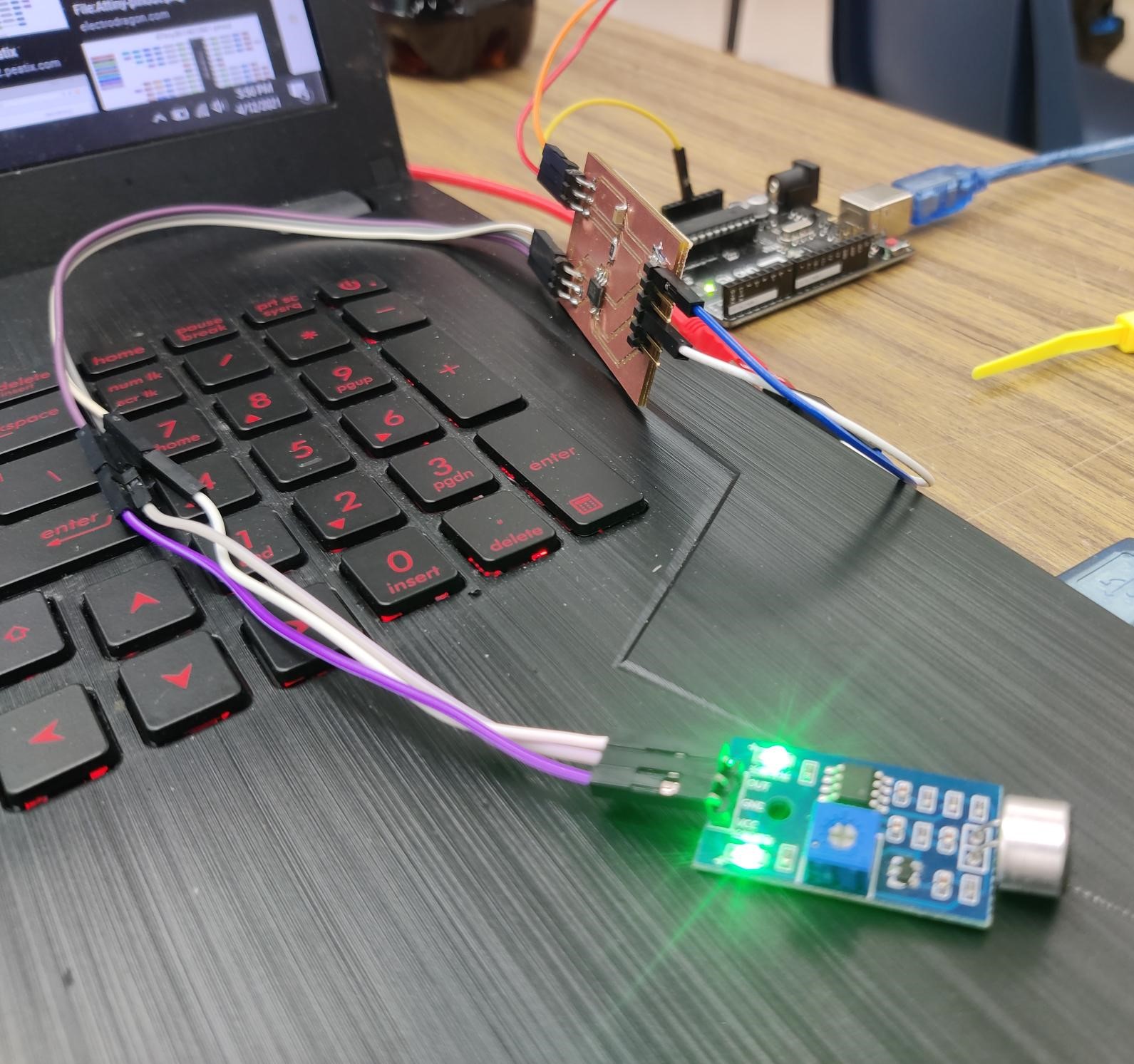
This weeks assignment was to add an input device to a microcontroller board that we designed. During my final project planning, I planned to use a microphone to pick up large spikes in volume that wouuld ressemble a clap. I when then use that to turn on or off the lights for my project. I used a ATTINY 412 chip that I have used in past week and referenced older board while making my design. For the group we needed to work on probing an input devices analog and digital outputs.
Designing my board
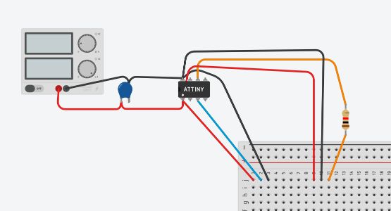
Before I began, I used tinkercircuits to create my circuit. Tinkercircuits doesnt have the tiny 412 chip so I used a tiny 45 instead. Both the chips are very similar and I encountered no isses. I started of by connect a power supply to the chip. In between this power, I connected a 1uf capaciter. I am still not to familar with the purpose of using the capaciter but I saw that there was always one in each board that we had used. I knew that I needed to add a resistor for the jtag.updi programming but I didnt include this on the tinkercircuits. I didnt think through the whole process to make sure that every part there before hand so when it came to finding the microphone, I wasnt able to use it. In the end, this brief exursion was useless and I continued on with the actual board in Eagle.
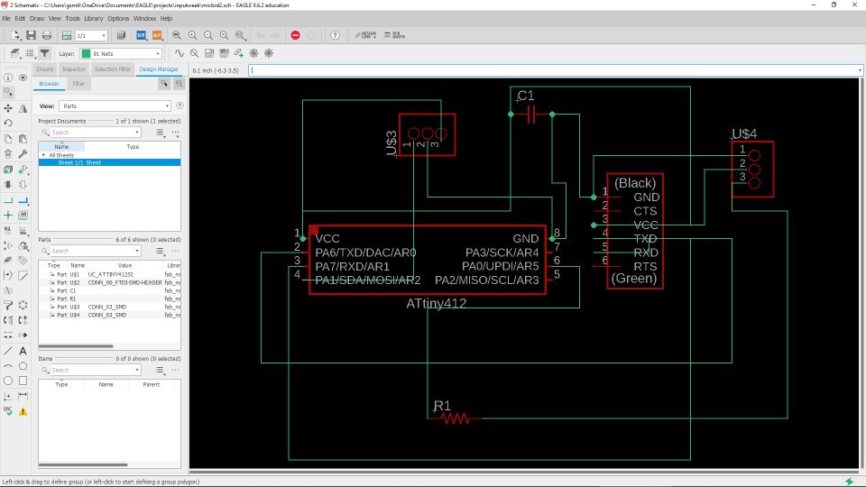
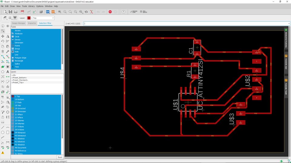
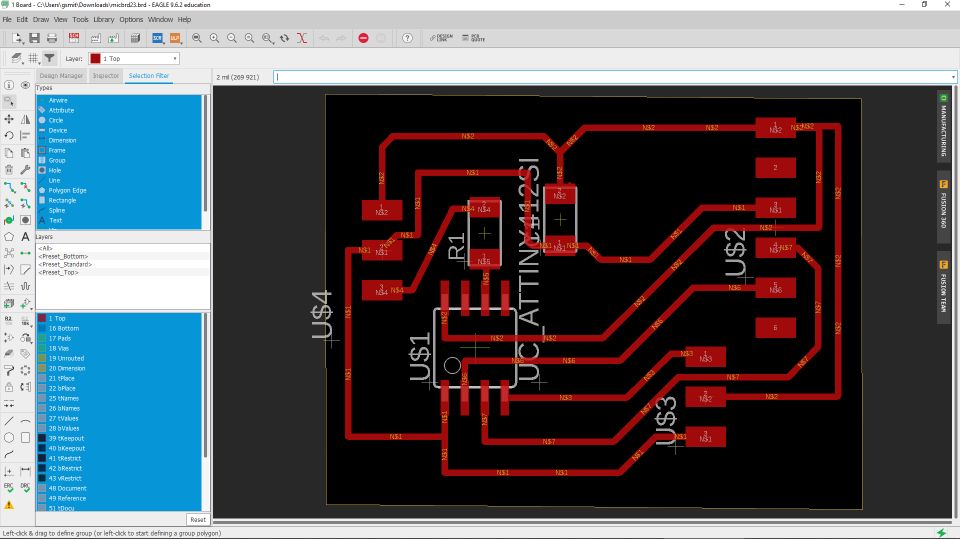
In Eagle the first thing I did was make sure that I had each component that I needed. From past experience, I knew that I had the correct resistors and capacitors but I still made sure that I had the correct chip. Since I was using a 412 chip, I needed to download the library for that which I did in the electronics design week. I also addedd two 3x1 surface mount headers and then a 6x1 FTDI header. I connected the vcc and ground from the ftdi header to the chip and then branched the other the two wires to the other two sets of headers. I interupted the two original headers with the placement of my 1uf capaciter. The next step was the wire the 4.7k from the updi pin to one of the 3x1 header pins that I had set aside. Once I had wired this all up, I wired the tx to tx and rx to rx. This really messed me up when testing but I was able to adjust it using jumper wires. In my second version of my board I fixed this. After I had everything wired up, I went back and checked through everything.
Milling my board
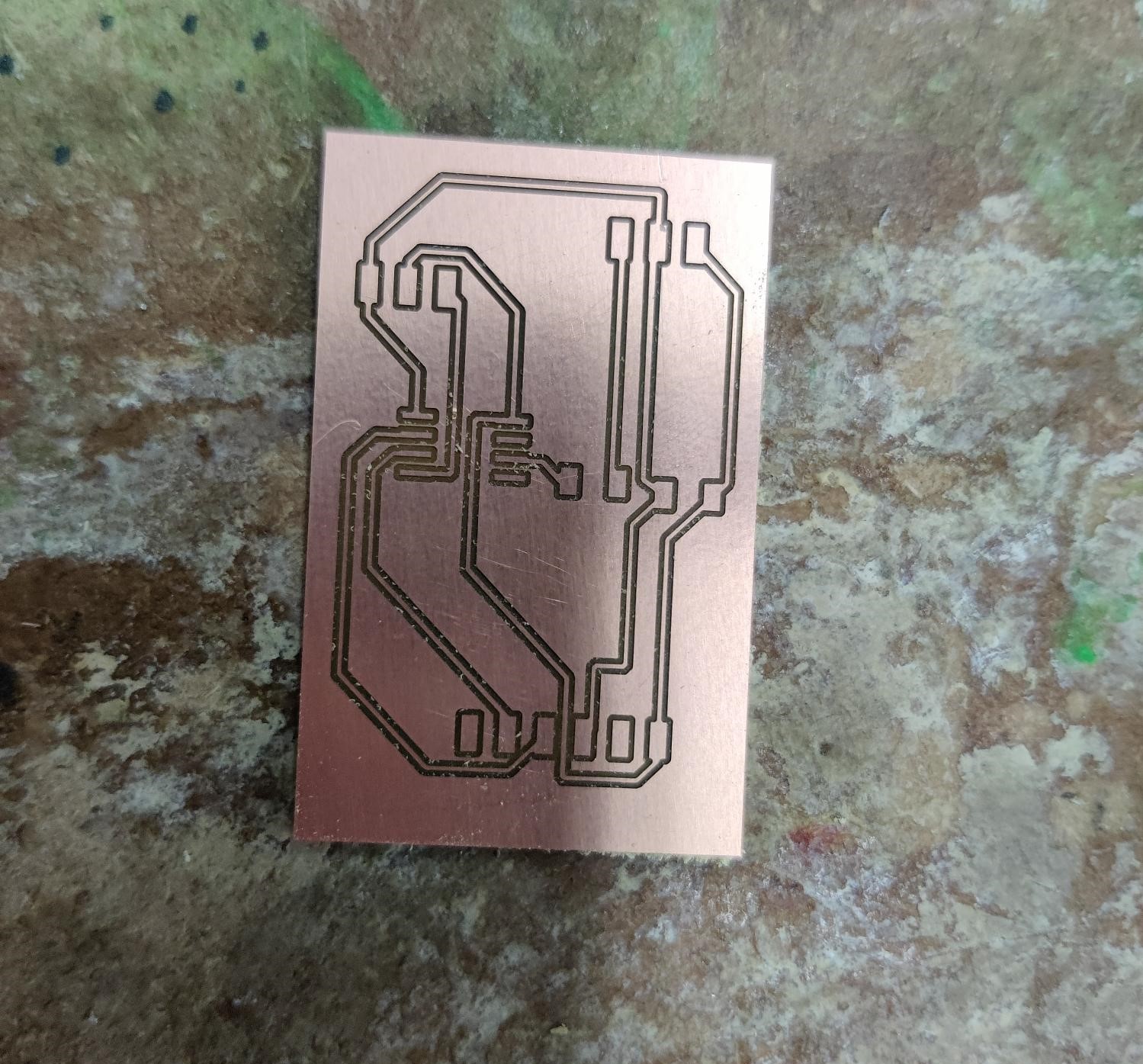
When I was milling my two versions of my board, I alternated between different styles and boards. For my first board, I used a 1/32nd bit as well as a finer .005 to get some of the tighter spots. I first inserted the board into the machine. Then I uploaded my file to drive and downloaded it on the local computer. Once I had it on the computer, I was able to get all the settings correct according to our workflow. After I confirmed all the settings I switched the bit and preformed the bit breaker command. This got the width of the material by electrically connecting the material to the bed. Once everything was set I ran the .005 and then, when prompted, switched to the 1/32 bit. This milled all the remaining copper away so that I could minimize the chance of cross contact.
Soldering my board
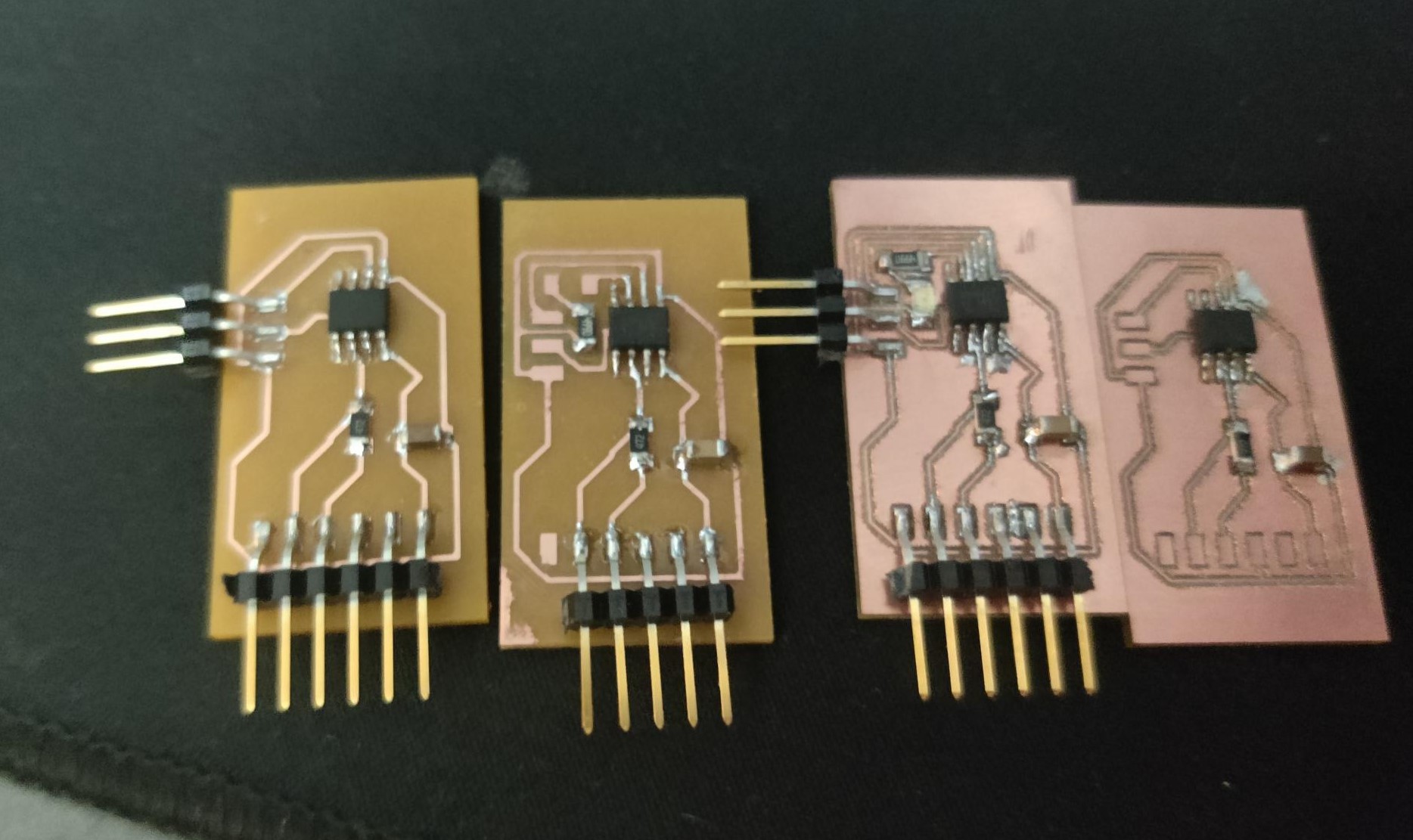
When I was soldering each of the five board I made this week, I started with the chip. On the first board, I managed to pull out one of the pins from the chip. I promptly threw it across the room and continued with the next. I moved to the capaciter and resistor after I soldered on the chip. The only remaining parts were the headers. For the first version of the board, I only needed 9 headers but for a special version I needed 12. The headers were extremely frustrating to solder since I couldnt line up each one for the life of me. After I failed many times, I had all the components soldered on the board. The first version of the board, While I believe that It would have worked, didnt have the correct pinout. Since I didnt know this and thought it was a soldering issue, I made another board. When this one also failed to work, I made a special board that had an led built in so that I could test to make sure that the pin was working correctly. When I couldnt get this to work, I had to reach out to my teacher.
Trouble shooting and coding
When I was trouble shooting my board I realized that I would need to add a second set of 3 pin headers. The first set would be used for UPDI programming and the second would connect to the microphone. Another issue that I encountered was the pins for rx and tx. I had orignally connected the rx to rx and vice versa. Therefore it was not reading any data and the serial plotter was left empty. I fixed this when testing by switching the pins on the FTDI chip with jumper wires but when I went back to make revisions, I fixed them. I went through once more once I had made the changes before I milled the final board. In the final version I decided to take out the led, since I was very confident that everything would work.
When I was coding my board, I was fortunate enough to get the code working first try. It was not hard at all to write these simple lines since all that I was doing was reading the input and then outputting it in the serial monitor. In the future, when working towards my final project, I will be able to tune the sensitivity so that it can turn my project on and off when I clap. I started to expirement with different uses for this but I didnt have the time to finish.
Here is my code
void setup(){
    Serial.begin(9600);
}

void loop(){
    Serial.printLn(analogRead(a2));
    delay(100);
}
I also included this line in the void loop when I was testing to make sure that I was outputting everything. Once I confirmed that everything was working, I took it out.
Serial.printLn("hello");
I did not end up needing to do anything to my code once I had it set but now have started adding it into my final project code that I have been working on. In the end I ended up working on making the board more compact. Here is what I came up with and I believe that it is as tight as possible.
Additional Testing
After I had got my board completed, I went over to our electronic shelf and found a similar board. I liked this board more because, after research, I was able to read the values in 3 different ways. The first way was called ‘gate’. What sets this one apart from the others is the way it displays the data on the serial plotter. Instead of any variety up to a certain value, It is practically bianary with either a high or low state. I found this one the best for my project since I plan on making it turn on when I clap. The other two modes, Envelope and Audio both appeared to be the same on the chart. I would have to look into both before I decided which one I may need. Below is a video on me testing
What I learned
This week I learned alot about the design process from start to finish. Compared to past weeks were all my groupmates were working on the same thing, I had to work through everything individually. This helped me understand what I was doing and what I was capable of. After this week concluded I started to design my final project board. I knew that I needed more components so I switched to an ATTINY 1614 chip. For Output week I want to add a custom led strip that I will be creating. I will incorporate one of these 5050 footprint leds into my design for output week but I may choose to do something a little different
Downloads
Code can be copied directly from the box
Groupsite
This week we needed to use an oscilioscope to probe the analog and digital signals of a sensor. I used a button and a potentiometer with teddy to test the signals. I wrote about our groups findings on the group site.