Electronics Production
This week was focused on learning how to use the CNC mill, in my case a bantam mill and soldering on the nessecary components. My groupmates worked on first our blinky test board and then moved onto a more complex programmer. There were major issues with both boards that I faced, but I was able to get through with the help of my partners.
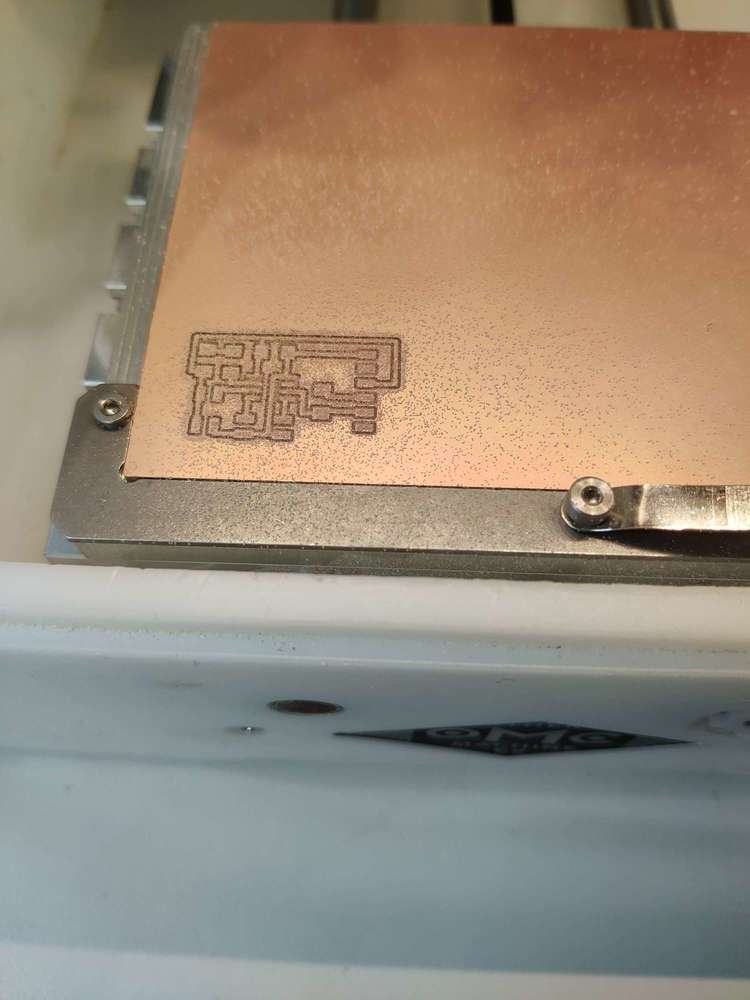
Milling the Blinky Board
Milling the Board was the easist part of electronics prodution. Our FabLab have really good Bantam mills whiich come with the Bantam Tool Software. The software is extremely easy to use and only took a matter of minutes to get a board milled out. You start off importing the file from a number of different formats. In this case we used the .brd files that EagleCad provides. Then you can see a variety of settings. The first thing that you want to do is make sure you have the correct bit installed or install a new one. This process is relatively easy. Then you will be prompted to use the ‘Locate Tool’ feature. This process is automatic and allows the machine to realize the size of the tool and how far it is sticking out. The next step is to locate the material. The best way to do this is to go into the bitbreaker menu and select ‘Locate Material’. It is extremely important to move out the electrical probe onto the surface you want to mill. If not the mill will not detect that it has made contact with your board. It is also crucial to move the probe off the board when the process is complete. I made sure that I had done everything right using the workflow that my teacher had put together. When the time came to cut, I put back on the side panels and used the 1/64th bit to mill out the traces. Next I changed the bit to a 1/32nd, reset all the settings, and then cut it out from the rest of the copper.
Soldering the Blinky Board
Since this was the first time that I had done surface mount soldering in a month, it took me a while to get use to it. I talked more about the strategies that I used to solder my chip in the student boot camp section but I will also breifly talk about it here. For the blink board, I would apply a a generous amount of solder paste on one side of the board while holding down the other half with a piece of painters tape. Then I would quickly sweep across to reveal perfect joints. If I had any doubts that there were bridges on it, I would use my schools electronic microscope to check. For one of the eight pins, I had a bridge so I used a pair of tweezers and the soldering iron to pluck through each one. The other components such as the capaciters and resistors, I was able to use a stick of soldering to get each one on. Where it was needed, I would also use some flux.
Testing the Code
Testing and Programming my board was by far the hardest part of this week. Teddy Warner and I spent a couple hours working along side an electrical engineer to get it working. The main reason that we contribute our struggle to was the lack of documentation on the subject by our instructor. The first thing that we had to do was download the MegaTinyCore library since we were using a atmel 412 chip. The we downloaded the jtag.updi folder from gitlab. This is where our struggles began. Some of the issues that we were having, we couldnt and still dont know where they were coming from but it is our guess that it was a combination of the 10+ different strategies that we tried while uploading sketches. The first error that I ran into was opening the jtag.updi sketch in arduino. What I had to do was take everything out of the zip file and move it into a folder called JTAG.UPDI. Then Arduino could open all the the different files within it. Combining this with the megatiny library, I was able to successfully upload the blink sketch from the Arduino Uno using it as a programmar, to my blinky board. A huge thanks is owed to Adam at SheekGeek for sitting on the phone with us for hours one night until we got this to work. Another key thing that helped us check to make sure our boards were working was the use of an LED to check if the Arduino was sending a signal to the blinky board. If the LED didnt light up or atleast flash, then there was no signal running to the blinky board telling it what to do. After countless unsuccessful attempts, we were able to narrow down the issue to the a wrong pin in our code. Since we were using a differnt pin, pin 0 in this case, the booard wasnt being detected properly by the arduino that we were using as a programmer.
Milling the Programmer
Milling out the programmer, just like the blinky board, was a painless experience. At this point, I was use to the Bantam tools software. For my programmer board, I used the .005 engraving bit compared to the 1/64th that I had used to mill my blink board. The main reason for this was my classmates ended up breaking two of the three 1/64th bits that we had. I found the .005 to work far better though. It cut out the traces more precisely which allowed me to solder them easily. I then used the saame 1/32nd bit to cut the board out the remaining copper.
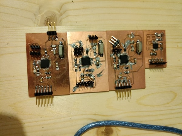
Soldering the Programmer
The programmer proved to be harder than the blinky board becuase of the way the chip was laid out. What I found worked best was using the same sweep technique but do it more carefully. I was able to so it successfully for three of the four sides but on the forth I had a small bridge that I got rid of. Every other component went on easily, or atleast I thought that until I tried to burn the bootloader and upload programmers. At the end of the first board, I accidently ripped off the the updi pin pad. For this specific week, my teachers recommended that I should remake the board instead of wiring up a jumper pin across the board. On my second board, everything went smoothly on the second one and no pads ripped off. However the second board gave back the invalid device signature which my fellow classmates found to be unconquerable. After double and tripple checking, I was able to get my third board to work perfectly and proceeded to upload the code in the next step.
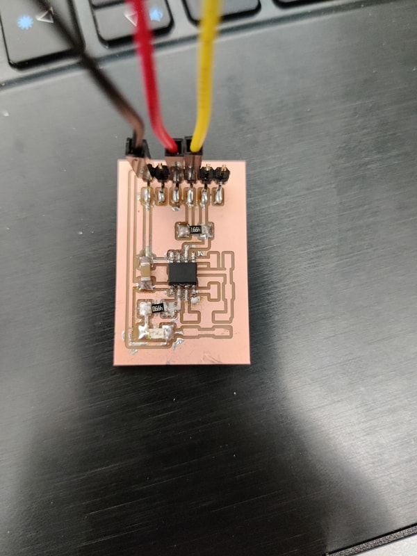
Testing the Code
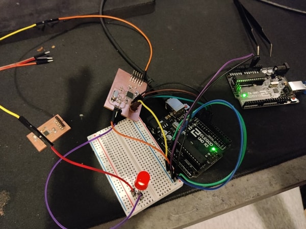
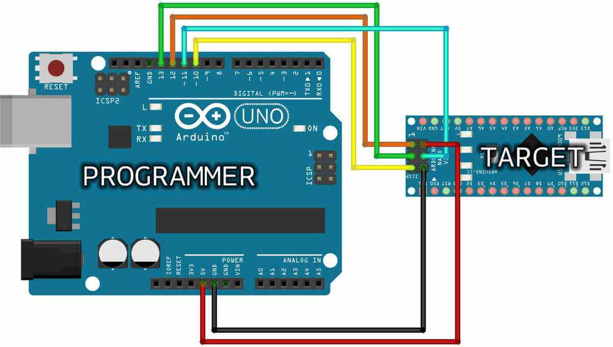
Since I had already programmed my blinky board, It was far easier to get my programmer up and running. The steps were basically the same and we didnt have to work through any of the errors that we had encountered with the other board. The first step was to wire up our programmer to something like an Arduino. In our case, we used Arduino Unos. The diagram that I used to wire was provided by Teddy Warner and is linked below. I flashed the ArduinoISP sketch onto the Uno. And then uploaded the blink sketch the my Programmar using the Uno as an isp. Since the sketch uploaded successfully, I knew that I could move on. The next this I did was burn the bootloader onto my programmer. With all the settings set up properly, I knew it would work and it did. The most important step came next. Cutting a specific pad on my board allowed me to keep the bootloader on the chip. If I didnt cut this pad, then the bootloader would have been replaced when uploading the blink sketch in the next part. After I cut it, I tested it out by connecting my programmer to my previously made blinky board. Using a FTDI chip, I was able to upload my blink sketch from my computer using my programmer to my blinky board. Unlike many other things during this week, It worked the first time and the sense of relief was amazing.
Problems
This first problem that I had thise week was soldering my board. Since I knew that the board itself would work, I knew it had to be myself. I narrowed down the issue to how I was soldering the chip for both the programmer and blink board. I was using to much solder paste so when I put the chip down onto the board, some of it would go under the chip. Then when I would heat it up, the paste would form a bridge underneath the chip where I couldnt fix it. I fixed this issue by only using solder paste on the first pad. This would allow me to still allign everything while at the same time limiting the amount of solder paste that could get under the board. Once I had done one pin and pad, I moved on with a regular rod of solder to do the rest and used my labs electronic microscope. Another Issue that I had was during programming my 412 chip. Since this was just the start of my experience with electronics, I was familar with how to program them. My issue was not uploading the JTAG.UPDI sketch properly and therfore my board was not being programmed. I fixed this by working along side all my classmates and testing on different computers.
Summary
Overall this week I learned so much. I was never really into programming or electronics before and I even thought that it would be miserable. By the end of the week though it really got me exicited. I learned how to use my schools PCB mills so now I can create any board I want. I also learned the foundation for how to debug when things dont go well. Because of this, Im ready to design my own board in the upcoming weeks.
Downloads
Group site
For this week I helped out by milling the ruler that was used to show the different trace clearance. I also spent somet time helping out by developing the chart that is on our website. The gorup project didn’t take much time, but was really helpful in furthering my understanding of the CNC.