Molding and Casting
This weeks assignment was to design a 3d mold and then mill it with one pass being a roughing pass and then followed up by a finishing pass. For my final project, I wanted to make a set of feet for each of my panels. I did so by creating a hard mold and then casting it in a soft to make a soft mold for my hard plastic final project.
What I Did
- Tuesday - Design my Fusion360 file
- Tuesday - Create my Fusion360
- Wednesday - Switch to Aspire for my toolpaths
- Wednesday - Design my vector, 2d file in Fusion360
- Wednesday - Create my new, 3d file in Aspire
- Wednesday - Create my toolpaths
- Thursday - Mill out my mold
- Thursday - Pour my silicone mold
- Friday - Pour my hard plastic final foot
In the below sections, I talk about how and why I did the things I did. There were some crucial desicions that I made this week that saved me alot of time.
Working in Fusion360
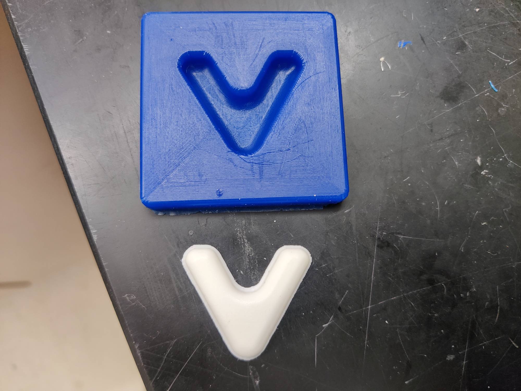
Originally I was going to use Fusion 360 to do my design as well as for my toolpaths. My design wasnt that hard to make in Fusion since im really used to using it. The first thing that I did was create two sets of two parallel lines. I made the angle where they connected up top 60 degress since all my panels for my final project are equilateral triangles. Once I made this v shaped object I connected the bottoms of each set of parallel lines. Then I used the sketch fillet tool to smooth out each part. Now that I had my design completed, I needed to create a box that sorrounded the peice I wanted to mold. I took the stock thickness into consideration as I did this. After I created my boax around everthing and made sure everything looked good, I started to create the toolpaths.
Toolspaths in Fusion360
Toolpaths in Fusion360 were the hardest part of this week. So hard that I ended up switching over to Aspire. I will still explain what I did in Fusion360. The first thing that I needed to do was set up the bit. The bit that I was going to use was a Bosch 85213M which is a 1/8th end mill. I then wrote down all the techincal specs on the sheet of paper below before copying it into fusion 360. Here is a helpful article I found here
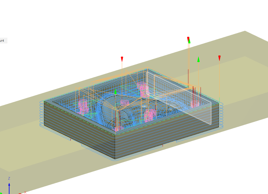
Now that I had my bit setup, I could move onto creating the toolpaths. The first thing that I did was used the 3d adaptive clearing tools. This si very similar to a pocket tools exept that it goes down on multiple layers to clear. This gave me a really good roughing pass for the inside that I could then follow up with a ball end mill. Once I had the inside roughing done, I used the same 1/8th bit to setup the outside contour cut. I selected to bottom of the model on the outside and Fusion360 calculated the rest. by this point I was already getting frustrated because it was so much harder to setup the toolpaths on Fusion than I expected. It took me even longer to setup the ball end mill because Fusion wanted even more information. I then used the same adaptive clearing tool to make the finishing pass and by adjusting the steps I was able to make it look really good. I was able to use the simulate tool to see if everything worked at it looked like it would. After I thought I had everything setup. I learned that I had done it all wrong. Instead of trying to fix my mistakes, I tried to use Aspire since I had never used it before for 3d models.
Working in Aspire for Toolpaths
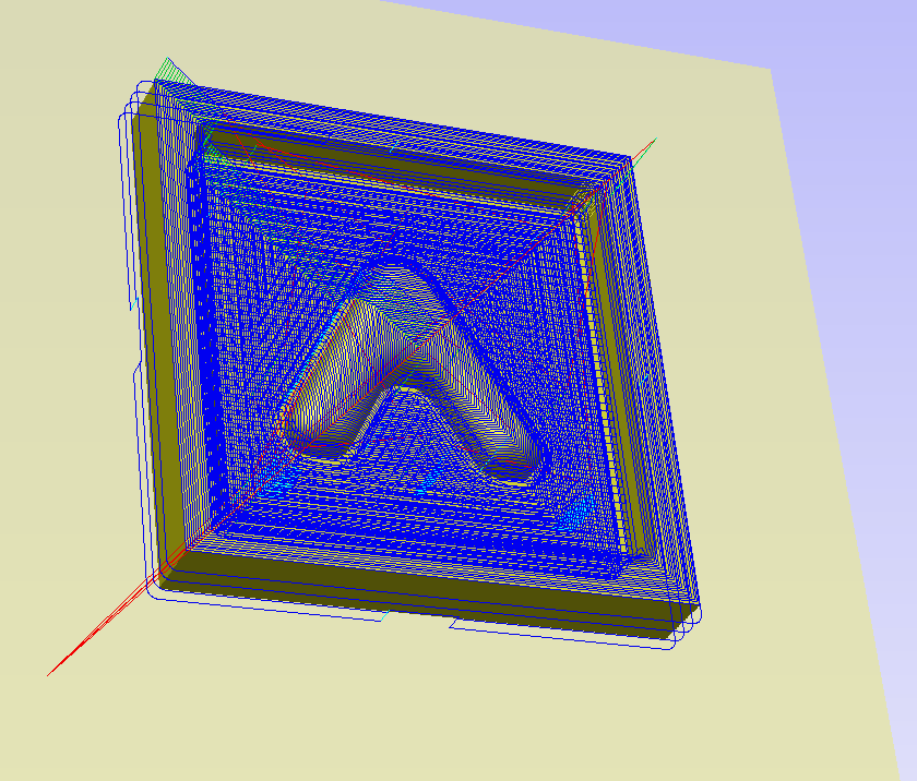
My original plan was to import the stl that I had made in Fusion to aspire and then create the toolpaths that way. Unfortunately, it is really hard to create them with a pre existing body. Instead it is easier to model what you are going for in aspire itself. I imported the svg of my design that I had mdae in aspire by exporting it as a dxf in fusion and then converyting it. I was then able to navigate to the model menu where I could adjust the heights and angles. I did look at a tutorial online but instead started to mess around. It allows you to create flat top shapes as well as shapes that are filleted. After I made the main body, I used the same vector to create the casing that went around it all. I chose a flat top and extruded it the thickness of my material (.4”). After this I went over to the toolpath menu and entered 3 values. After this, the bit was setup and I was able to start creating the toolpaths. From this point on everything was easier in aspire and I hope to explain the differences. The first this I did was use the contour tool to make the outside of the mold. In that menu, I selected to add two tabs. After I had this peice selected properly by clicking on the perimeter vector, I moved onto the inside. Aspire is really simple in this resort as there are only two ways to clear the inside. The first is a roughhing pass and the second is a finishing pass. Of course I used the roughing pass and flat end mill and then used a ball end mill for the finishing pass. Once I had this all done and I could verify that in the preview, I was able to easy export the toolpaths for the shop bot.
Using the Shop Bot
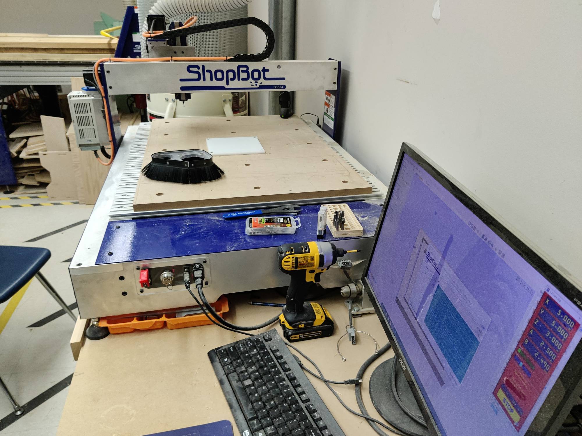
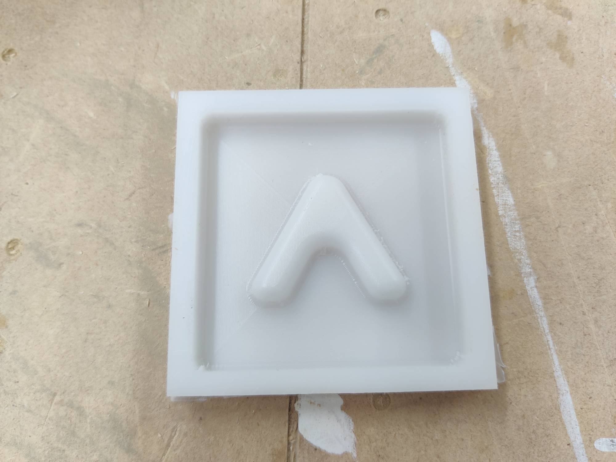
After I set up my toolpaths, I was ready to start using the machine. The first and most important thing that I did was pull up my labs workflow and review basic safety. The entire workflow is linked on my CNC week page. After I had familerized myself with the machine once more, I used started the spindle warm up sequence. This took 15 minutes and doesnt allow you to do anything else on the computer while it is running. I checked over my toolpaths on my laptop using the free aspire trial. After checking to make sure everything looked good, I got my peice of stock and screwed it down in four corners after remeasuring to make sure everything was correct. I then put in the 1/8th flat end mill bit into the collet and used the zero plate to zero the bit. I then used the j2 command to move the machine to the corner of my stock where I wanted it to home. I wrote down the points 14.5, 9 in chase I needed to come back on a different day and mill the same peice. Once everything was zeroed off, I used the 3d offset tools to run an air cut. This aircut looked like it was going to work so I started to make prepartions for the actual cut. I made sure that the dust collector was on and that all other ports connected to it where closed. I also made sure the brush attachment was secure to the spindle. I then ran the same file with no offset and it worked. The first roughing pass took 5 minutes. Once it was completed I checked to make sure all looked well. When I was checking I made sure to turn the spindle key off so that there was no way for me to be injured. I then ran the finishing pass after switching out the flat end mill for a ball one. This cut took longer as it required more detail (about 20 minutes). Once this cut was done, I checked again. It too looked good so I swapped out the bit for the flat end mill once more before I ran the outline. The outline only took a minute so once it was done I took a picture. I used a chizel and mallet to remove it from the rest of the stock after I turned the machine off. The final result came out good but there was still small fibers that where sticking out. I used a knife to cut these little areas out. After that the mold looked perfect.
Pouring the Flexible Silicon
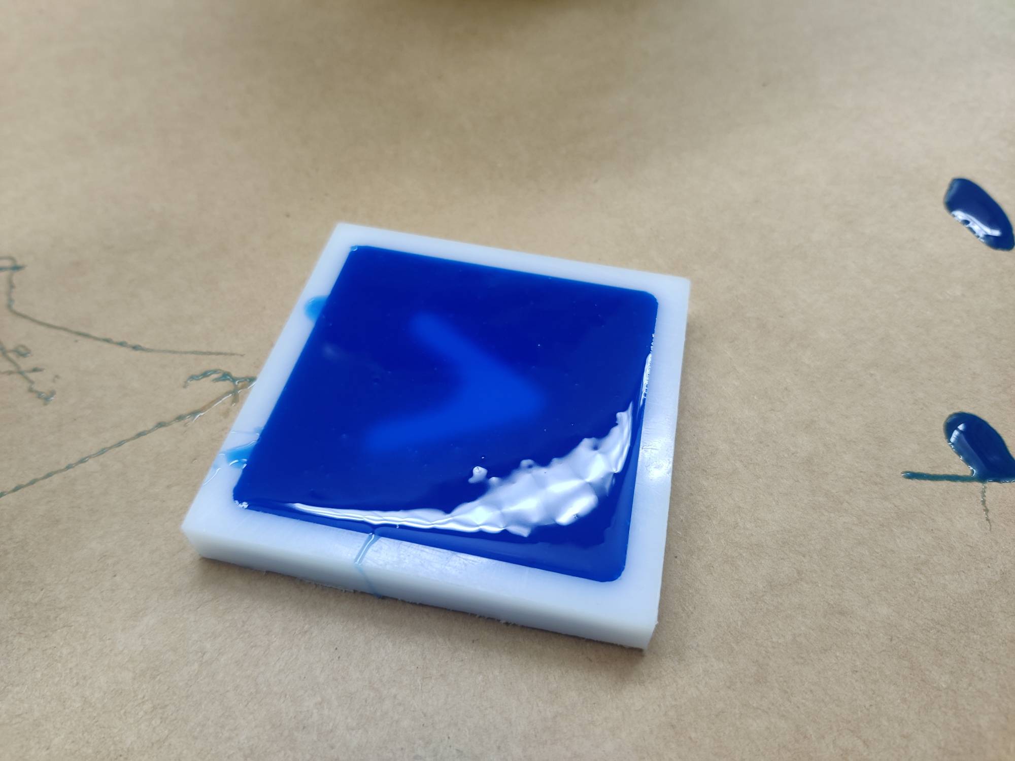
Before I was able to pour the material, I needed to read the datasheet. Here I was able to find a few important details. I used the moldstar 30 from our lab. It has an 8 hours complete cure time and a 15 minute pot life. As I read further, I learned that I didnt need to use a degasser since the viscosity was 15000. I also didnt need to use mold release although it did recommend it. Once I had the basic techanical data known, I started to mix the materials. I used two cups and a scale to make sure that I got the proper 1:1 weight ratio. After this, I used neils technique to mix the two liquids. After I mixed for the suggested 5 minutes, I sprayed some mold release onto my polyethelene and then poured the liquid according to neils suggestion. After I poured it, I used my hands to tap the bubbles out. There werent any bubbles after about one minute of tapping to I left it to sit overnight. When I came back in the morning, my blue silicone cast had finished. I was able to use a knife to pry it out of the hard mold. I then was able to use the hard plastic to cast. I also used a different silicone material that cured alot faster. It did come out with a little more bubbles but didnt require a degasser.
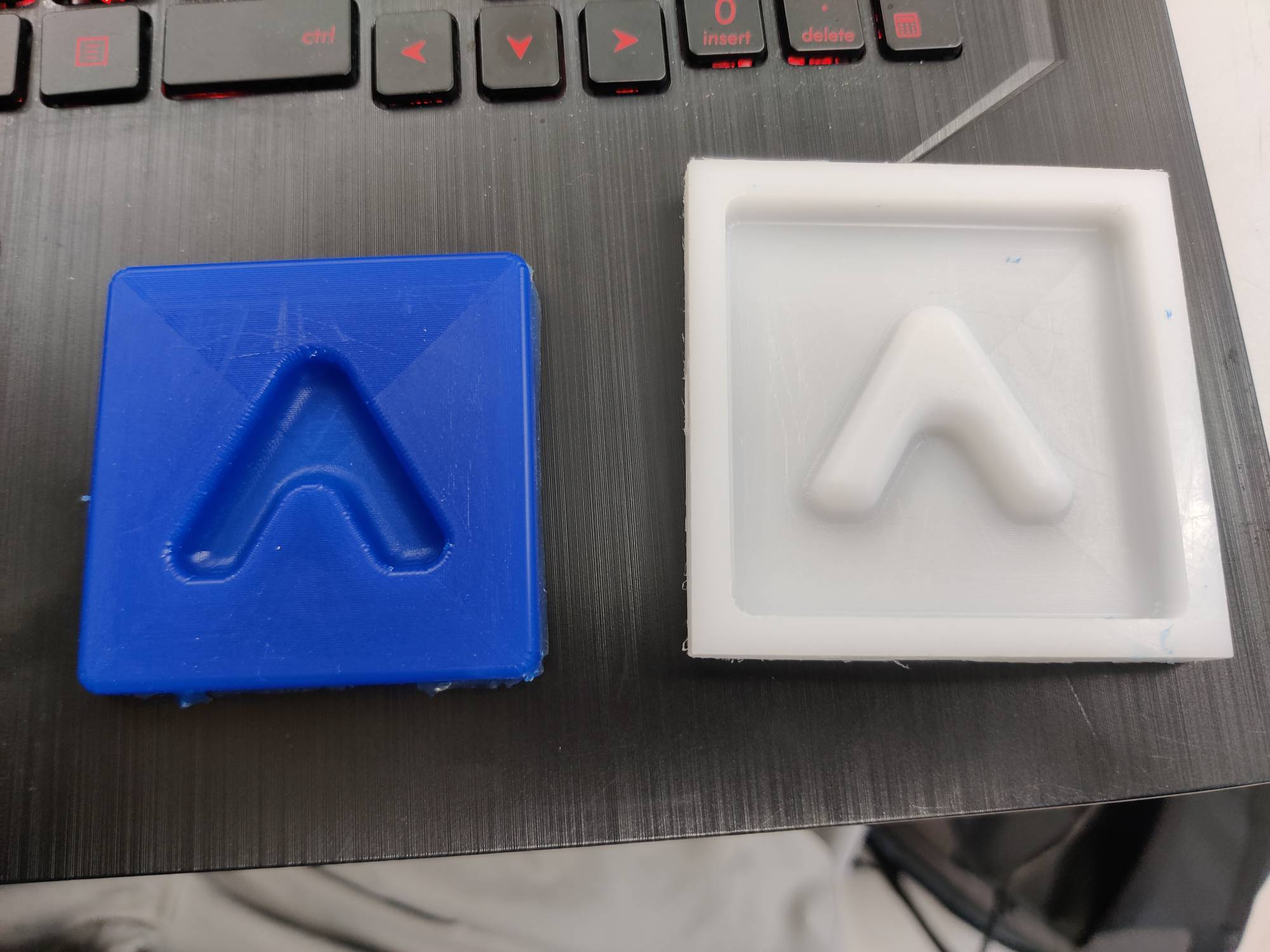
Pouring the Hard Plastic
The hard plastic was far harder to work with than the soft plastic. The main reasons are the very, very small potlife and the equally as small set time. I used this datasheeet to gether the same information that I had gathered for the silicone. I used the same scale and different cups to get the 1:1 ratio that it required. After that I mixed the two together for only a minute before I sprayed the mold with mold release and made the pour. After I had shaken it around to get all the bubbles out, I started to pour the extra into a scrap cup that I had. As I was pouring, the material hardened leaving a really cool sculpture in the cup. I also used an infared thermometer to see how hot the temperature was since I could feel a difference. At its peek it hit 154, which wasnt that much but could cause really minor burns. After I finished messing around, I went back to my cast to see how it turned out. It looked excellent and popped right out of the mold. I did a little bit of post processig with some sand paper before I started to wrap things up.
What I learned and Where I struggled.
This week I leanred alot about the pros of using a mold to make parts. I am now able to use those two molds I made to make tens, if not hundreds, of parts. It will really be able to help me at the end when I need to make alot of these very similar peices. If I could go back and change one thing, I probably would have made it where my final project would be made of silicone. I plan on experimenting to see what really happens if you pour a soft materials into a soft mold and will make sure to update my site when I am done. The hardest part of this week was creating my design. I tried to elaborate it as much as possible in the design section but I will go over it again here. It was really hard to create the toospaths in Fusion so I needed to switch over to aspire. It also worked out well because I was able to learn something new by switching. I also had an issue where the top of the mold and top of the thing I wanted to mold where to close together. Although I was able to get it working, I would need to go back and edit it if I planned to do it again.
Group work
This weeks group work was to use a few different materials from around the lab and test them in a mold we made. My personal contribution was creating the file and using the CNC to help create it. After that, teddy and others worked with the different materials.