Output devices
This week I worked on developing the led system for my final project board. I was originally going to use the sk9822 LED which has 6 pins but after some research and trials, I discovered that the ws2812 would be a better option. I will be talking through how I made my desicions in the section below. Other critical desicions were determining which chip I should use. I had been using the ATTiny412 chip for quite some time now so I stuck with it. For my final project however, I decided that I would use a 1614 chip. It is very similar to the 412 but has more pins which I can use for inputs and outputs.
Designing My Board
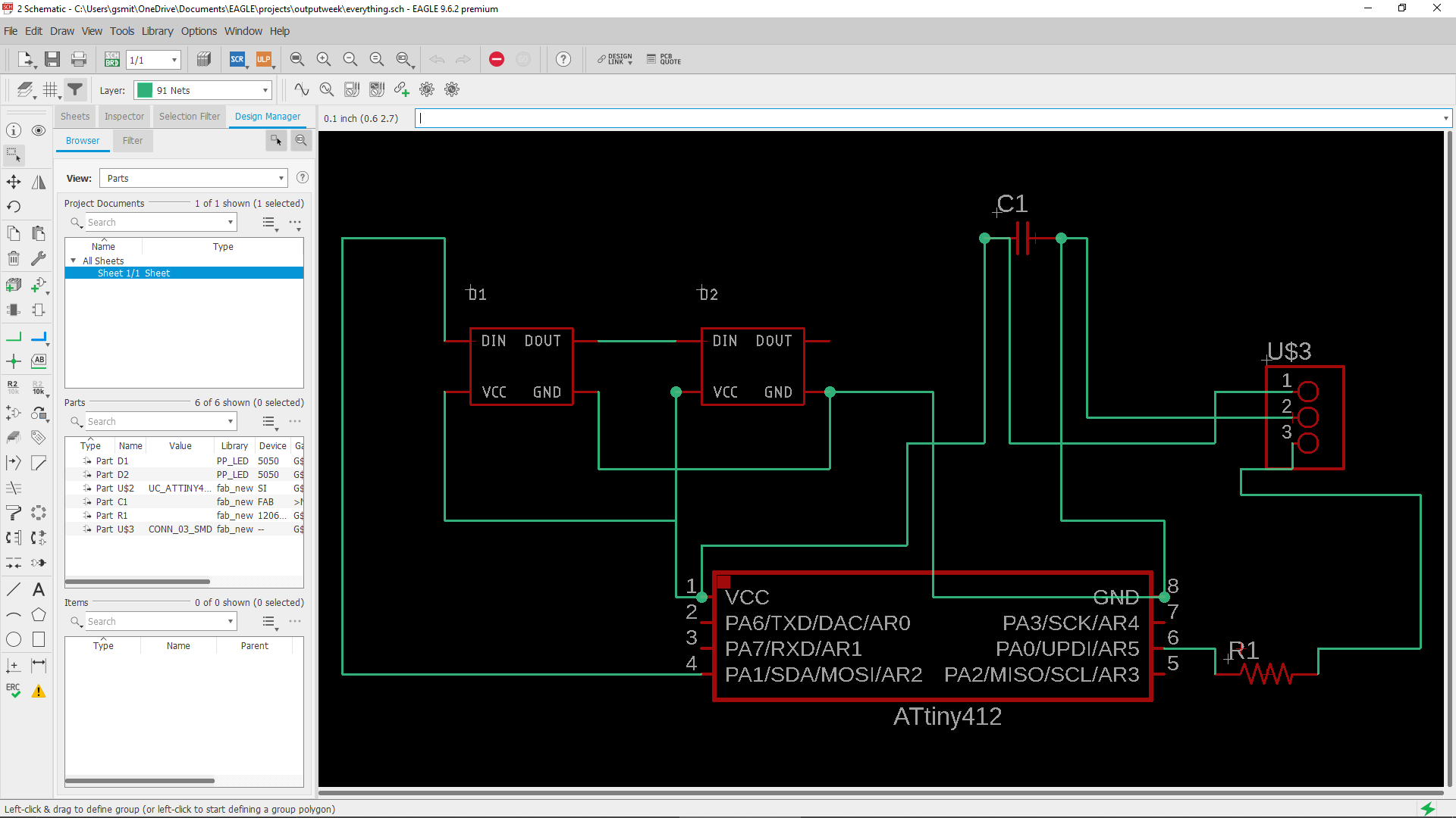
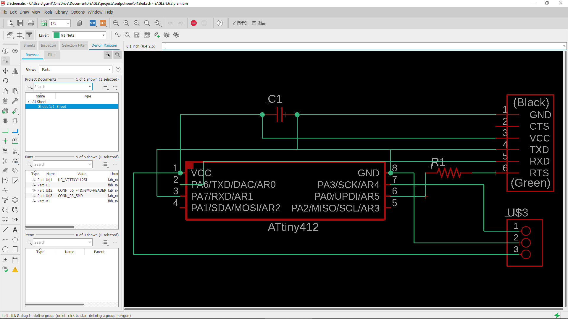
I used a very similar schematic to what I used for input week. Instead of the 3 pin header, I used an RGB LED and connected it to is respective pins. I started off by dragging each compnent onto the shcematic work space. Here is my parts list:
| Part | Library | Quanity |
|---|---|---|
| 412 Chip | Fabnew | 1 |
| 1uf capacitor | Fabnew | 1 |
| 4.7k resistor | Fabnew | 1 |
| 3x1 header | Fabnew | 1 |
| RGB LED | Fabnew | 2 |
While I wrote down two leds on the parts list, Our lab didnt have anymore besides one that I luckily found in the bottom of the bin. I made two spots on my board however to show that it would work with multiple. I tested it used a strand that I soldered realy quick. For the first rendition of my board, I used a second 3x1 header so that I could test it with an led strip. You can see the test here. As I connected all the wires in Eagle, I had my input schematic pulled up. I connected the 4.7k resistor to the UPDI pin on the 412 and put the capaciter in between the ground and power. I then wired the extra 3x1 header to the pin I wanted to become an output and the power and groud pin. I then proceeded to mill this board out to test. When It came out ok and I was able to get everything working on the first try, I added on the RGB LED in place of the extra 3x1 header. Once I checked over all of this again, I was able to mill out my board.
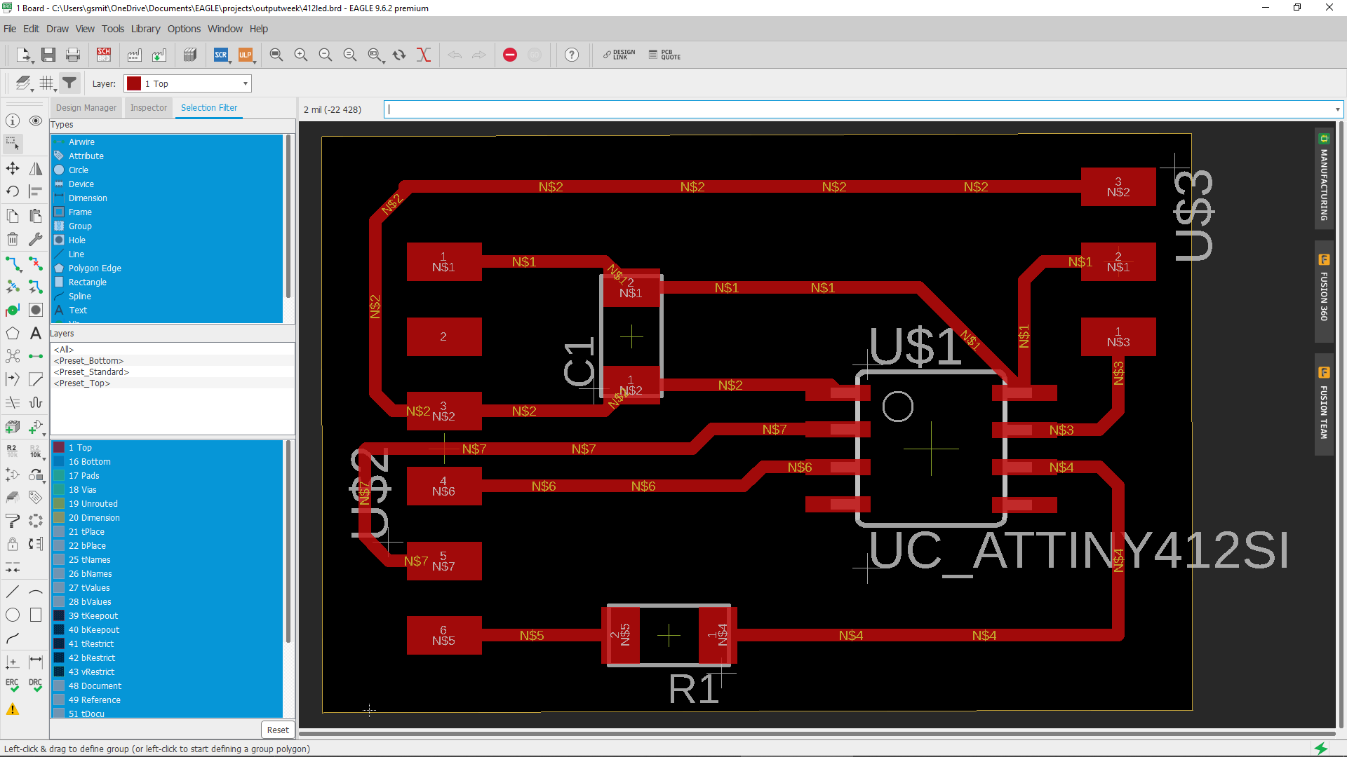
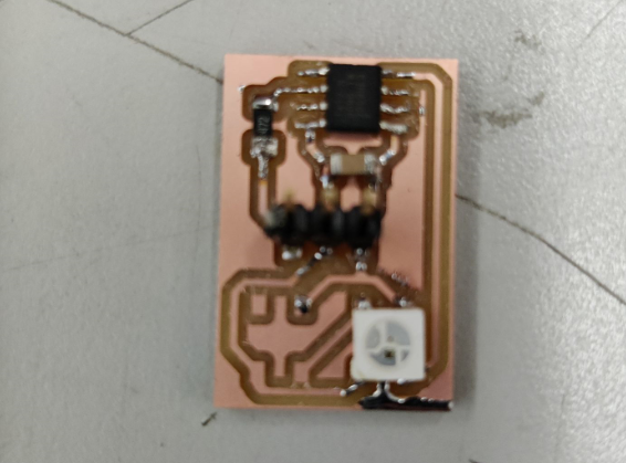
Milling My Board
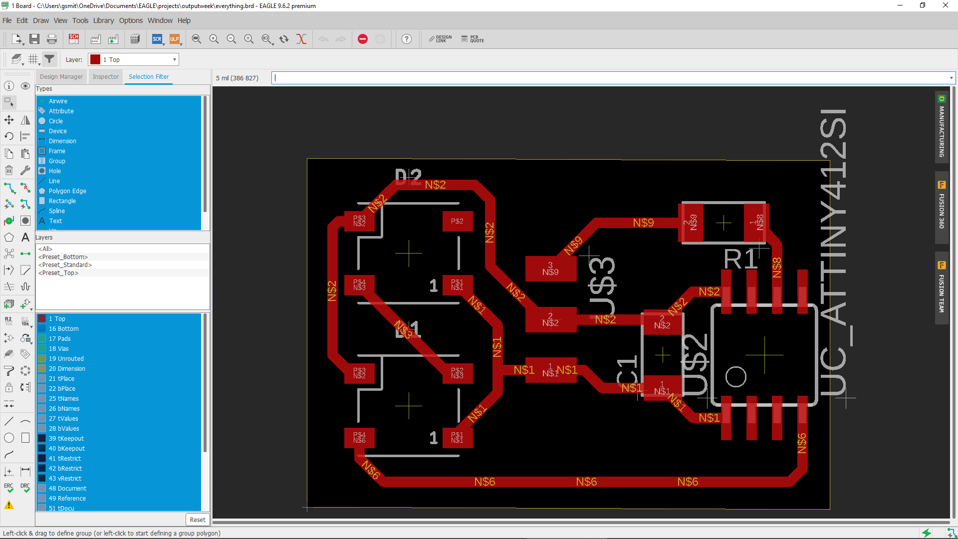
Milling out my board was the easiest part of this week since I had become so familar with how the mill work since I had been using them so often. I loaded my file from my laptop into drive and then downloaded it on the local computer. I then set up all my settings that I had now memorized and ran the cut. It went really well the first time with the traces so I changed the bit and started to cut out the board from the rest of the stock. This is how it came out:
Testing My Board
Before I could test my board I needed to solder it. I started off with the chip and then moved onto the capacitor and resistor. As I worked, I used a multimeter to check for any shorts if I had any doubt. When everything went on smoothly, I plugged it into an arduino to see if it was shorting. It wasnt so I moved onto programming. The first thing that I needed to do was upload JTAG to my arduino. I thought I already had it on since I have been using the same arduino all along. I still took the extra time to re upload it. After that I was able to start trying out some code. The first thing that I tried was using regular strand test from the adafruit neopixel library. When this worked on the arduino, It didnt work on the 412 chip. After some research, I was able to figure out that I needed to get the tiny neo pixel library. It was by the same guy that made the rest of the 412 librarys that I had been using so I found it quite easily. Here is a link to it: Library Download I was then able to open it up and install it. After I installed the library, I had access to a pre written test code. I was able to use this code by changing the amount of leds in the strand to 1 and changing the pin to pin 2.
Code
#include <tinyNeoPixel.h>

#define PIN 2

tinyNeoPixel strip = tinyNeoPixel(7, PIN, NEO_GRB + NEO_KHZ800);


void setup() {
  strip.begin();
  strip.show();
}

void loop() {
  colorWipe(strip.Color(255, 0, 0), 50);
  colorWipe(strip.Color(0, 255, 0), 50);
  colorWipe(strip.Color(0, 0, 255), 50);
  theaterChase(strip.Color(127, 127, 127), 50);
  theaterChase(strip.Color(127, 0, 0), 50);
  theaterChase(strip.Color(0, 0, 127), 50);
  rainbow(20);
  rainbowCycle(20);
  theaterChaseRainbow(50);
}
void colorWipe(uint32_t c, uint8_t wait) {
  for (uint16_t i = 0; i < strip.numPixels(); i++) {
    strip.setPixelColor(i, c);
    strip.show();
    delay(wait);
  }
}
void rainbow(uint8_t wait) {
  uint16_t i, j;

  for (j = 0; j < 256; j++) {
    for (i = 0; i < strip.numPixels(); i++) {
      strip.setPixelColor(i, Wheel((i + j) & 255));
    }
    strip.show();
    delay(wait);
  }
}


void rainbowCycle(uint8_t wait) {
  uint16_t i, j;

  for (j = 0; j < 256 * 5; j++) {
    for (i = 0; i < strip.numPixels(); i++) {
      strip.setPixelColor(i, Wheel(((i * 256 / strip.numPixels()) + j) & 255));
    }
    strip.show();
    delay(wait);
  }
}

//Theatre-style crawling lights.
void theaterChase(uint32_t c, uint8_t wait) {
  for (int j = 0; j < 10; j++) {
    for (int q = 0; q < 3; q++) {
      for (uint16_t i = 0; i < strip.numPixels(); i = i + 3) {
        strip.setPixelColor(i + q, c);
      }
      strip.show();

      delay(wait);

      for (uint16_t i = 0; i < strip.numPixels(); i = i + 3) {
        strip.setPixelColor(i + q, 0);
      }
    }
  }
}


void theaterChaseRainbow(uint8_t wait) {
  for (int j = 0; j < 256; j++) {
    for (int q = 0; q < 3; q++) {
      for (uint16_t i = 0; i < strip.numPixels(); i = i + 3) {
        strip.setPixelColor(i + q, Wheel((i + j) % 255));
      }
      strip.show();

      delay(wait);

      for (uint16_t i = 0; i < strip.numPixels(); i = i + 3) {
        strip.setPixelColor(i + q, 0);
      }
    }
  }
}

// Input a value 0 to 255 to get a color value.
// The colours are a transition r - g - b - back to r.
uint32_t Wheel(byte WheelPos) {
  WheelPos = 255 - WheelPos;
  if (WheelPos < 85) {
    return strip.Color(255 - WheelPos * 3, 0, WheelPos * 3);
  }
  if (WheelPos < 170) {
    WheelPos -= 85;
    return strip.Color(0, WheelPos * 3, 255 - WheelPos * 3);
  }
  WheelPos -= 170;
  return strip.Color(WheelPos * 3, 255 - WheelPos * 3, 0);
}
Since I didnt know what inputs were going to contribute to working these, I didnt take the time to create my own version of the code. I did see some notable patterns however that I could replicate however.
Video of It Working
What I learned
This week I learned alot about how my output device will work. Since this is an integral part of my final project, It is really important that I learn how to use them. Now that I have completed this week, I will be able to work on connecting all the different parts together.
Group Site
This week we needed to measure the power consumption of an output device. We decided that we were going to use a motor. While Drew Griggs was the leader this week, I helped out by setting everthing up the correct way. site link