Networking Week
For networking week we were tasked with creating wired or wireless nodes. I focused this week on figuring out how I could use a bus addresses for each panel and control it with one master board. To test this I made a teacher board with would represent my main board and then I made a student that when the correct value was sent, would turn on an led. I plan to use this to allow me to send a specific value and get a specific color or pattern as a result. I did a part 1 and a part 2. In part one I used a regular led and then I made a whole RGB led version
Part 1
Designing my boards
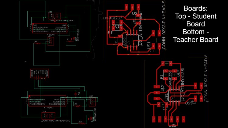
Both of the two board were very similar. For the chip I used a ATTINY 412 and then supplied power to that with a capaciter in between. After I had the power system setup, I added a 3 pin headaer on both for my UPDI programming. On one of the pins I included a built in 4.9k ohm resistor. On the master board I made included a ftdi header so that I could plug it in and read values if needed. After that, I placed a 499 ohm resistor and led in series going to pin 4 on both boards. I would use this later on to test. I then created a 2x2 header that would hold the RX, TX, power, and ground. These would be the pin that would power the slave board. I put them on both so that I would be able to create an endless chain if need be.
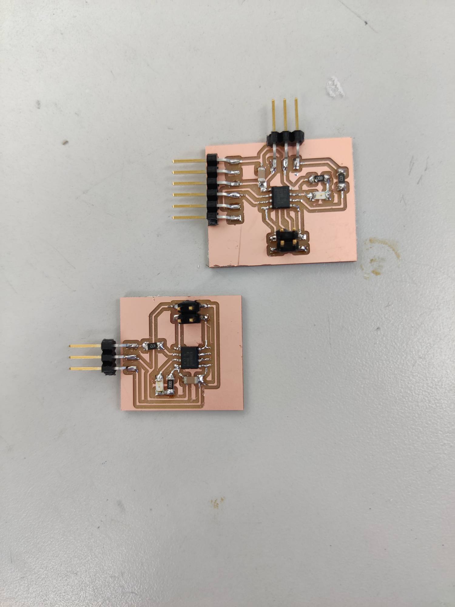
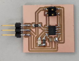
Milling and Soldering
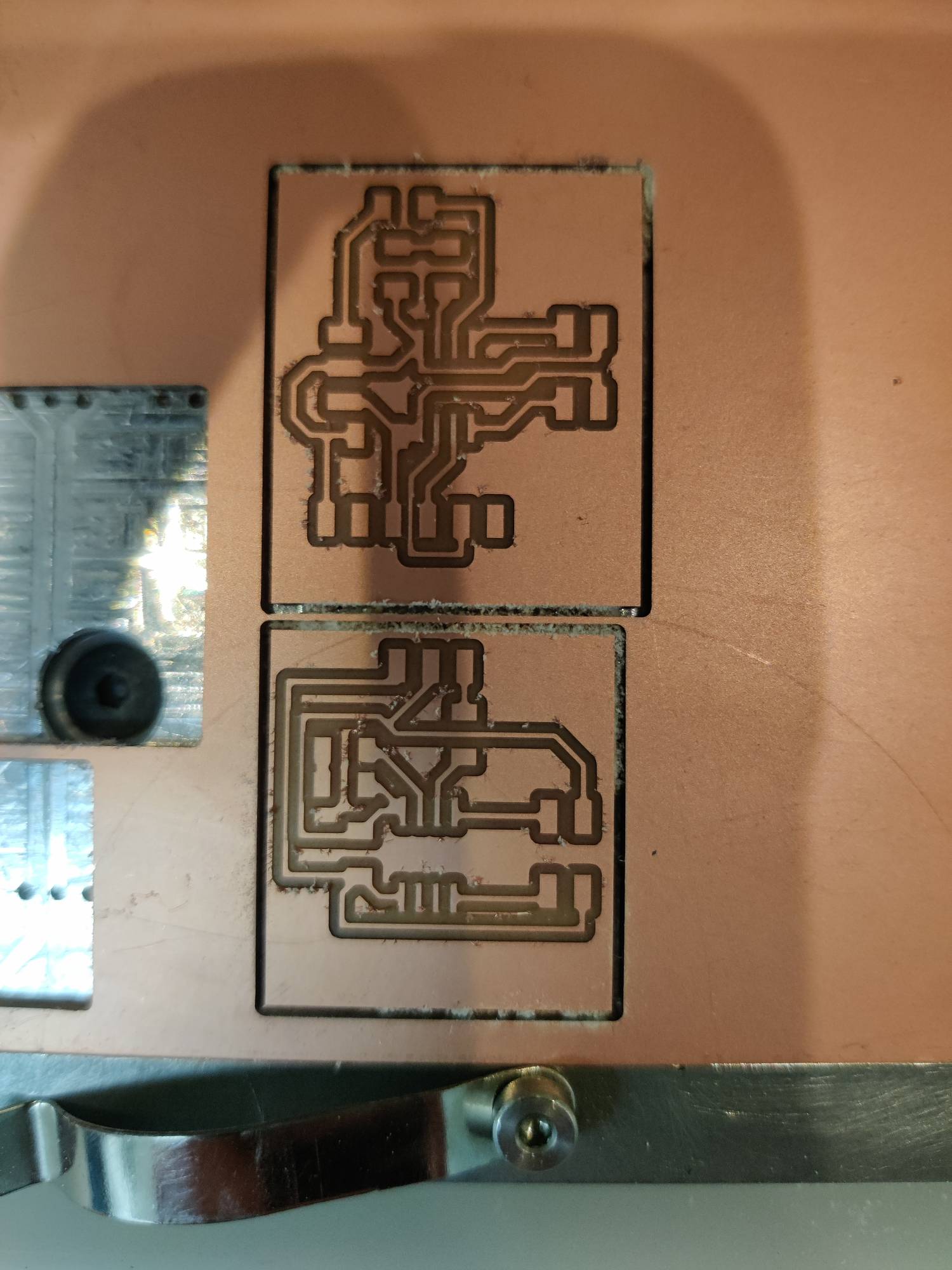
Since ive done so much of this in the past weeks, I didnt feel like it was needed to redescribe the process once more. I did however take photos to show what the board looked like after being milled and soldered. Here they are below.
Testing the teacher
The first thing that I did as I tested my boards was to run a simple blink code. I had added an led on each board just for this reason. Once I could see that my boards were taking uploads form an arduino I was using with Jtag.updi, I started to come up with the code that I was going to use for this week. The basis for my code was for it to print any value between an adjustable range that I set. But before I could get this code working, I wanted to run a simple test and manualy print something to serial. I chose to write testing and I could read the values through an FTDI chip. I put this on the existing tx pin on my board. I verfied that everything was working when I got the proper testing value in the serial monitor. The final code for this week was very short. In the setup I defined the baudrate that I wanted to use for serial. After looking through work from past years, It appeared that 115200 was the proper baud rate. I set it as that and then moved into the loop. For the loop I created a variable called “i” and then set it so that it would be any number less than three. After it determined which value “i” should be, It would print that value and delay a second. The result when hooked up to a FTDI chip was a random change between the numbers 1 and 2. After I could see that it was printing as I wanted it to, I was able to set up my student board.
Testing the student
Just like I did for the teacher board, I first ran a simple blink to make sure it was receiving uploads. Once I saw this, I then ran a similar test with the testing value. Although I did send anything back to the teacher board this week, I did plan on using it for my final project. I used the same FTDI setup and was able to see the testing value. I then needed to start working on my final code for this week. FOr this week I planned on turning on an led everytime that a 2 was sent from the teacher board. In the setup, I identified pin 4 as the led output on the board and also the baud rate of 115200. In the loop I created an if statement that read the serial and would turn on the led depending on what it read. I used this forum to help me figure out the best way to do this. I used serial.avaible to make sure it would only react when the value was available in serial and then used the serial read to compare the incoming value to what I wanted. Then I used a digital write line to turn on and off the led at the end of my if statement.
Putting it together
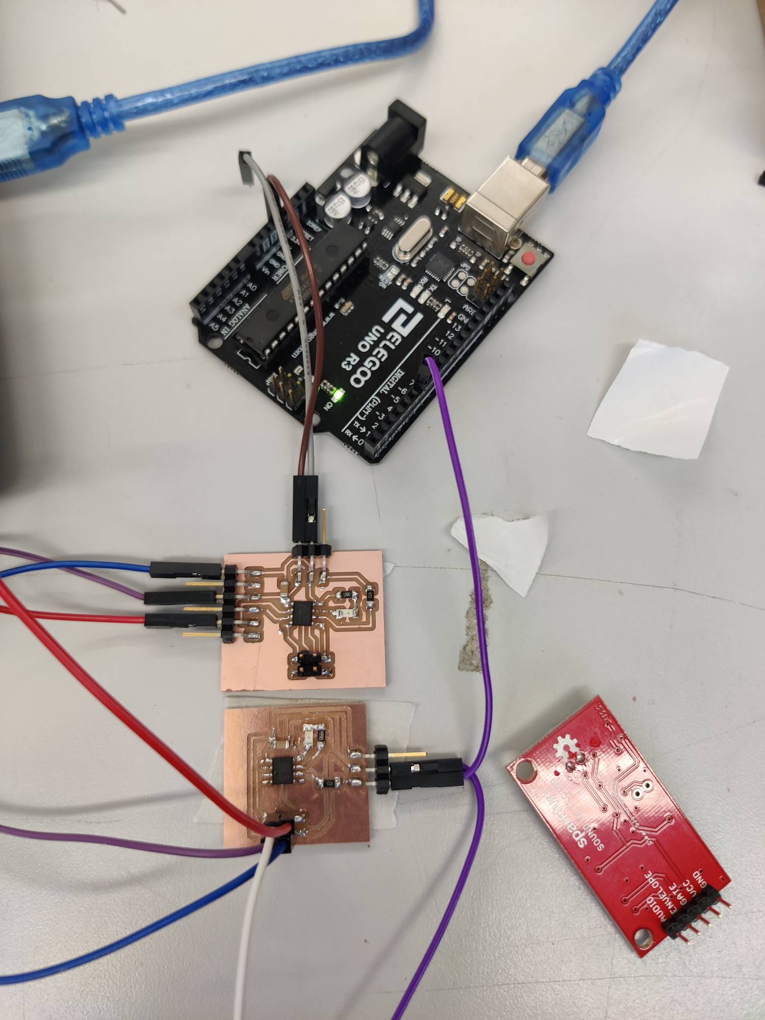
I wired the two together using power and ground from an arduino, to the teacher, and then to the student. I did the same to ground and then found the tx pin on my teacher board and the rx pin on my student board. I then linked the two together. After that, with the code already on each board, I plugged it into my laptop for power. It worked the first try so then I started to mess around with it and see what else I could do. During this period, I was able to add simple additions like if the value was “1 and 5” and “1 or 5”. It gave me a pretty good idea of what I needed to do for my final project.
What I learned and Where I struggled
This week I learned alot about how I could do my final project. Originally, I was going to place just a strip in each panel without a micro controller, but now I know how it works and have already started on getting that working. This has opened a new door where I can be more creative with what I do to each panel. The main area that I struggled with was the code. I have never been that good at code so I had a few slip ups on the way. The first area that I struggled in was printing the proper value from serial. At first I was getting the same value every time but in the end I realized the I needed to do a delay and change the sign. After this I didnt have any other issues this week.
Part 2 - RGB LED
In this section I used a RGB LED instead of a regular single color LED. I had started to use them in the output week
Designing my board
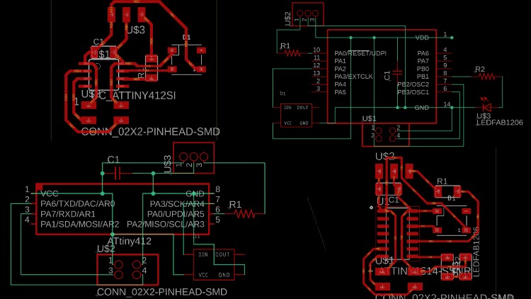
The design for my board was very similar to my first board but instead I had power, ground, and a digital pin going to the led. I kept the same capacitor and used the same 412 chip. For the main board, I started to mess around witha 1614 chip. I couldnt find the library for it so instead I went over to a peers schematic and copied his 1614 chip. After I did this, I pasted it on my schematic. This worked really well. The reason I switched is because I needed more pins for my final project. Other than that, everything was the same.
Testing my board
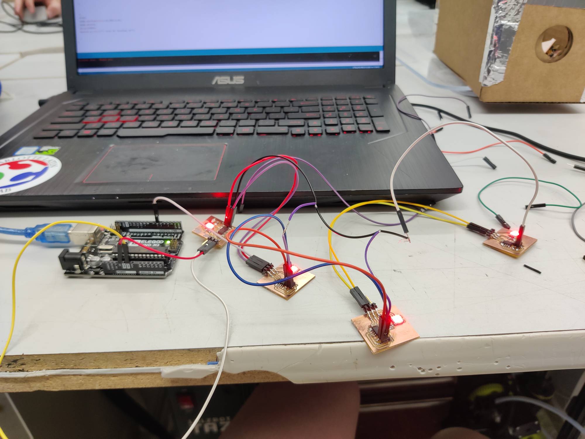
Since I had switched to a different kind of led, I needed to figure out the code to operate it. The first thing that I did was use the master code from my led board and edited it. Inside it, I included aa simple blink where the led would turn from red to blue after each time it printed something. It ended up working well the first time because I could see the values being printed to serial via FTDI. After I had the main board done, I started to work on the student board. This code was alot harder to work with and ended up taking me a few days. I was trying to adapt my existing code and add from a different RGB led code that I had made. This was working but for some reason the variable called ‘numleds’ wasnt working. I ended up deleting this variable and just putting in the number it represented. This ended up working and therefore all my code was working. I wired everything up and created a 1 to 3 adapter for all my nodes. This worked aswell and I could finaly see my project. I now know how im going to make my final project and have most of my boards working aswell.
Groupwork
This week we networked two boards from different projects. I spent most of my time documenting this week wile Drew and Jack worked on the code. site