-
00. FA20 Hyunho
-
01. Principles and Practices, Project management
-
02. Computer-Aided design
-
03. Computer controlled cutting
-
04. Electronics production
-
05. 3D Scanning and printing
-
06. Electronics design
-
07. Computer controlled machining
-
08. Embedded programming
-
09. Input devices
-
10. Applications and implications
-
11. Output devices
-
12. Interface and application programming
-
13. Invention, intellectual property, and income
-
14. Networking and communications
-
15. Molding and casting
-
16. Wildcard week
-
17. Mechanical design, Machine design
-
18. Project development
-
19. Final Project
Week14
Networking and communications
Group Assignment Link
Assignment
I2C communication consists of one line(SDA for sending and receiving data and one clock line(SCL) for synchronizing the timing of transmission and reception. It consists of one master and more than one slave and can theoretically connect up to 127 slaves
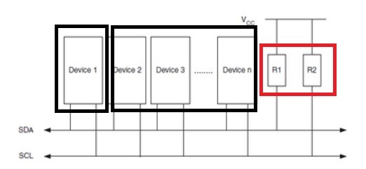
In the picture above, one of the 'Device n' becomes the master and the rest becomes the slave
The point to note is the resistor of R1,R2. Because both SDA and SCL lines must be 'HIGH' for communication
It is important to make them high with pull-up resistor
[What is pull-up register?]- I referred to Ji-hwan Kim's works
I will use the Arduino Uno board and the Arduino uses the internal pull-up resistance, so there is no need to attach or set the resistor
The advantage is that you don't have to set the speed of communication like serial communication
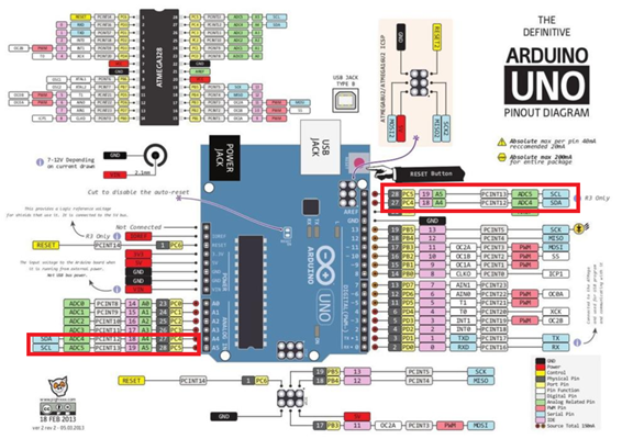
In Arduino Uno A4 pin is SDA, A5 pin is SCL
Arduino addressing
Identifications between Arduino are distinguished by addresses
Here's how to address
Wire.begin // master
Wire.begin(address) // slave (7bit)
Data transmission
When you send data, the beginTransmission(address) and endTransmission() functions are paired and the data is sent to that address as an write() function
Wire.beginTransmission(1); // Start sending slave address 1
Wire.write ("good\n"); // send string
Wire.endTransmission(); // abort transmission
Data reception
Once the data is received, the receiveEvent function is called after only one representation of the setup() function
Wire.onReceive(receiveEvent); //recall data reception receiveEvent() functions
Request/Reply
How to request data from a particular slave Arduino and send data after confirming the request
Wire.requestFrom(1, 4); //Request 6byte to Slave(1)

when (Wire.available() { //Read data when sent
char c = wire.read();
Serial.print(c);
}

Wire.onRequest(requestEvent); //call each time requested

void requestEvent() { //Action on request function
Wire.write ("ok!\n");
}
I2C Inter-Aduino Communication Circuit Diagram
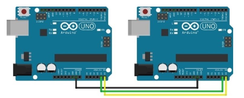
Connect the vin on the two Uno boards and connect them to the computer
coding
I'll combination of Master Reader/Slave Writer, Master Writer/Slave receiver in Arduino example>wire code
Master board code
#include <Wire.h>

void setup() {
  Wire.begin();        // join i2c bus (address optional for master)
  Serial.begin(9600);  // start serial for output
}

  int x = 0;

void loop() {
  Wire.beginTransmission(1);
  Wire.write("good\n");
  Wire.write(x);
  Wire.endTransmission();
  x++;
  if(x==6)x=0;

  Wire.requestFrom(1, 4); //request 4 bytes from slave device 1
  while (Wire.available()) {
    char c = Wire.read();
    Serial.print(c);
}
  delay(500);
}
You can prevent conflicts by providing a delay() function between data transfer and data request
Slave board code
#include <Wire.h>

void setup() {
  Wire.begin(1); //slave address
  Wire.onRequest(requestEvent); //Invoke requestEvent function on demand
  Wire.onReceive(receiveEvent); //Recall the responseEvent function when receiving data

  Serial.begin(9600);
}

byte x = 0;

void loop() {
  delay(500);
}

  void receiveEvent(int howMany) { //Read Transfer Data
  while (Wire.available()>1) {
    char ch = Wire.read();
    Serial.print(ch);
  }
  int x = Wire.read();
  Serial.println(x);
}
void requestEvent() { //On-demand action function
  Wire.write("FA20!\n");
}
Code Upload process
1.Upload the code after connecting Master Arduino with your computer
2.Upload the code after connecting Slave Arduino with your computer
3.Verify Serial Monitor After Connecting Master Arduino Port
Result
1.Master Arduino sends a "good" string and an x-value from 0 to 5 to Slave Arduino
2.Slave Arduino reads the value of the transmitted "good x-value" and outputs it as a serial motor
3.Slave Arduino sends the "FA20" character column value to the master Arduino when the data request is received
4.and Master Arduino reads the "FA20" character string and checks the serial monitor to see if the request/response has been processed properly
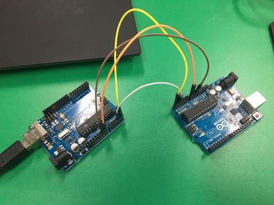
I2C Arduino UNO - Attiny1614 board
Lastly, I will use the board I made and the Uno board to I2C communicate
Attiny1614 board Link
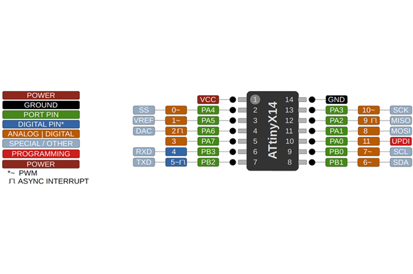
Attiny 1614 pinout
Attiny1614 PB0/7/SCL - Arduino A5
Attiny1614 PB1/6/SDA - Arduino A4
First, I used UPDI to put the Slave code on my board
How to program Attiny1614 board using UPDI Week8 Link
And I program the master code on the Uno board
Laptop > UNO(master) > Attiny1614(Slave) > FTDI > Serial Monitor
This Week Hero Video!
Reference Link