-
00. FA20 Hyunho
-
01. Principles and Practices, Project management
-
02. Computer-Aided design
-
03. Computer controlled cutting
-
04. Electronics production
-
05. 3D Scanning and printing
-
06. Electronics design
-
07. Computer controlled machining
-
08. Embedded programming
-
09. Input devices
-
10. Applications and implications
-
11. Output devices
-
12. Interface and application programming
-
13. Invention, intellectual property, and income
-
14. Networking and communications
-
15. Molding and casting
-
16. Wildcard week
-
17. Mechanical design, Machine design
-
18. Project development
-
19. Final Project
Week6
Electronics Design
Group Assignment Link
Assignment
I started by referring to the Fab Academy Tutorial
Eagle Tutorial Link
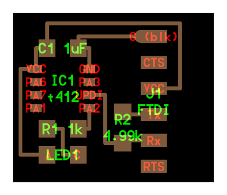
This is 412 Hello-EcoBoard
I'm not going to use a serial monitor
So I don't need FTDI fins
I will programming using the updi pin
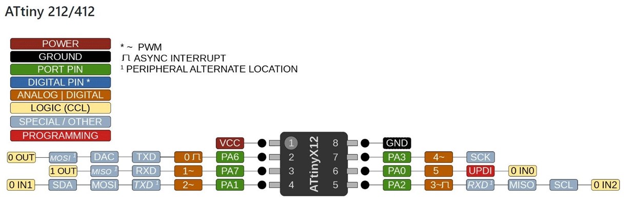
Attiny 412 pinout
0, 1, 2 pins are LED
4pin is a button
5pin will connect UPDI
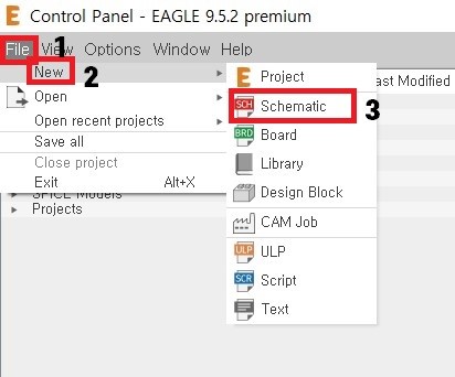
First open Eagle and File > New > Schematic
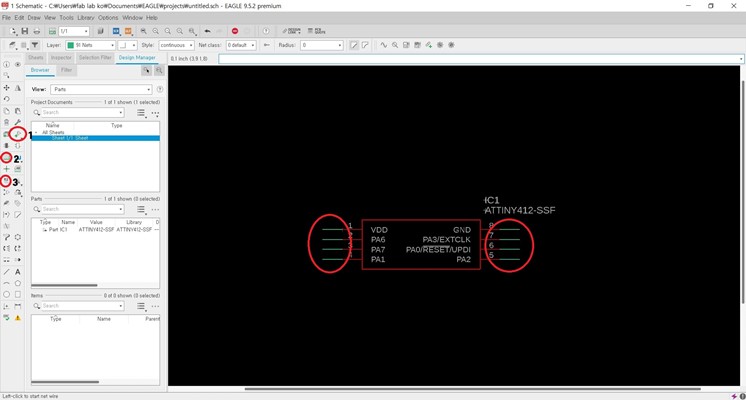
1. add component (Ctrl + Shift + A)
2. draw line (Alt + N)
3. name
Draw a circuit diagram in the order above
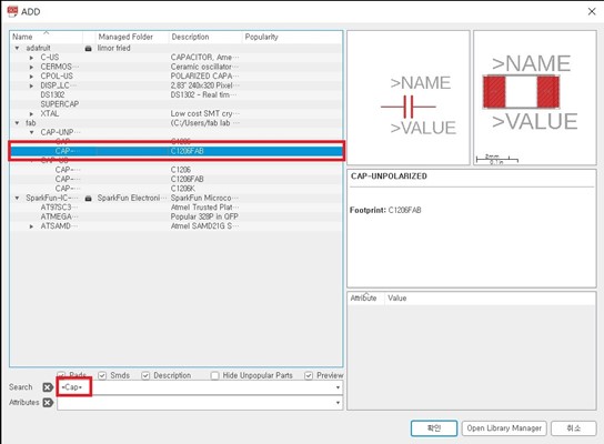
When searching for components, it's easy to search by attaching a '*' on both sides
Pre-add 1206 C and R used in fablab
[SnapEDA] - This site makes it easy to find the ibr file containing the desired footprint
[FAB.ibr]
[ATtiny412 datasheet]
[ATtiny412.lbr]
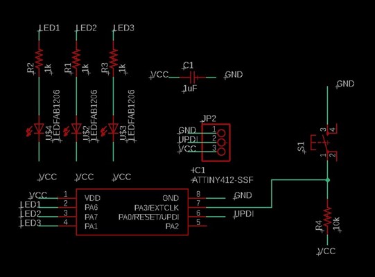
I've added 3 LED and button,
I found the resistance value of 1k through this link
and used a pull-up register
[What is pull-up register?]- I referred to Ji-hwan Kim's works
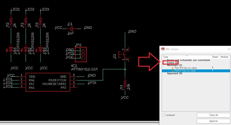
design rule check (Ctrl + Shift + E)
Make sure there are no errors through the and move on to the board
(You can ignore the warning)
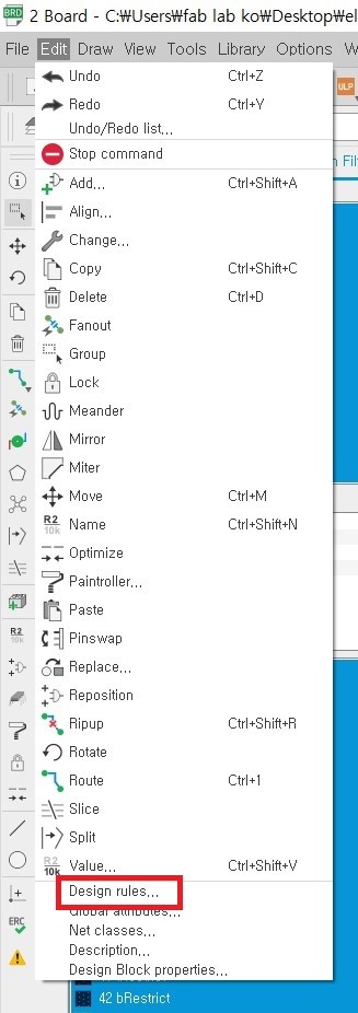
Let's move on to the board
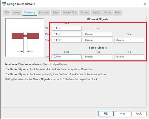
First, set the design rules
In the [4th week of the group work], we learned the minimum value of 0.4mm.
Set all settings to 0.4mm
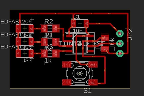
Place the Capacitor closest to MCU VCC and GND to maintain potential difference
Make the yellow box efficient after connecting the wires
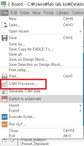
gbr file export
File > CAM Processer
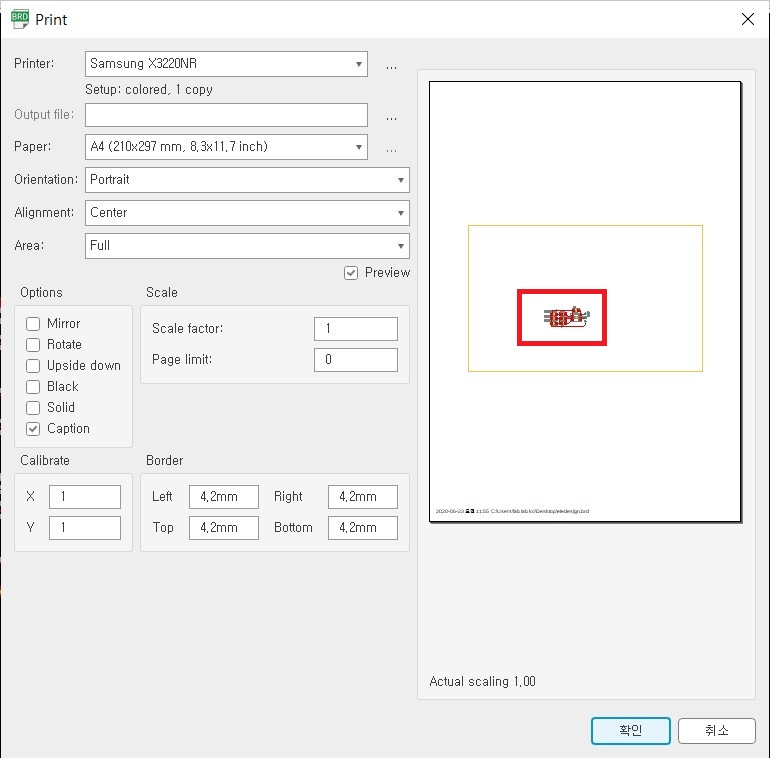
Print through (Ctrl + p) before export
True-size prints can help you size up real-world components and reduce mistakes
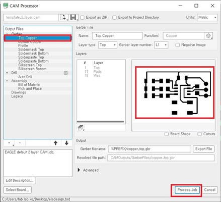
Check it again on the top copper and press process job
The gbr file is a great formate that includes both an outline, holes and a copper
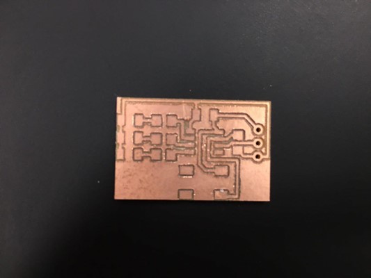
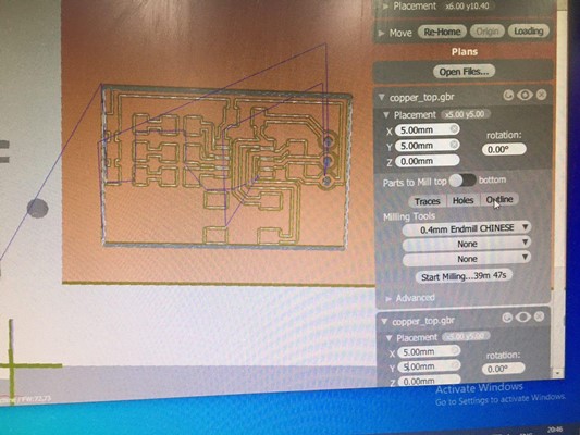
coin-sized circuit board
Milling took about 15 minutes
Clearance should be given at least 0.5mm to make it easier to soldering
Bantam PCB use Link(week4 group work)
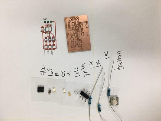
To check components our 1206 resistance is out of stock
So i use a different resistance
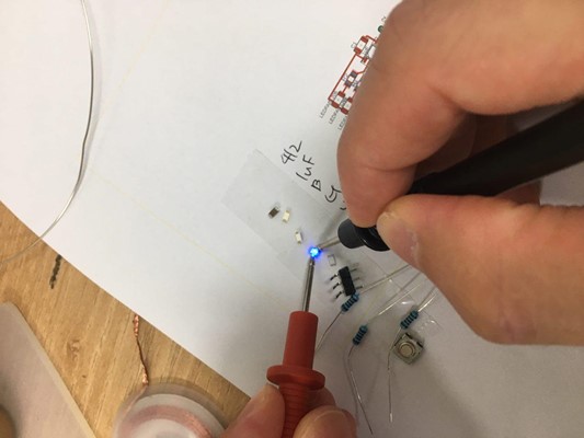
The LEDs are on + and - so be careful
Check the multimeter for the direction of the light
Let the red part go to the VCC
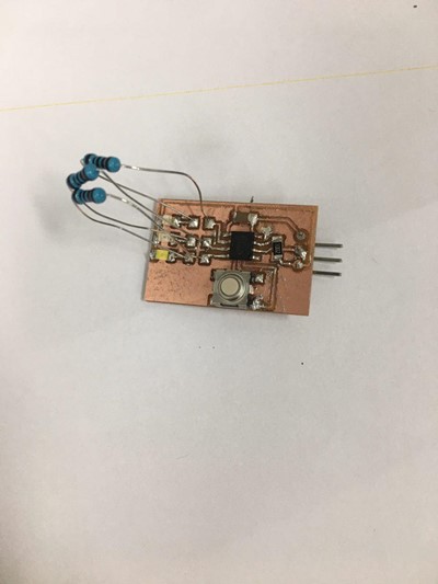
completed circuit board
File
circuit board SCH file
circuit board BRD file