-
00. FA20 Hyunho
-
01. Principles and Practices, Project management
-
02. Computer-Aided design
-
03. Computer controlled cutting
-
04. Electronics production
-
05. 3D Scanning and printing
-
06. Electronics design
-
07. Computer controlled machining
-
08. Embedded programming
-
09. Input devices
-
10. Applications and implications
-
11. Output devices
-
12. Interface and application programming
-
13. Invention, intellectual property, and income
-
14. Networking and communications
-
15. Molding and casting
-
16. Wildcard week
-
17. Mechanical design, Machine design
-
18. Project development
-
19. Final Project
Week11
Output devices
Group Assignment Link
Assignment
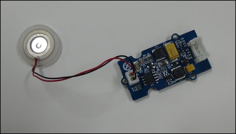
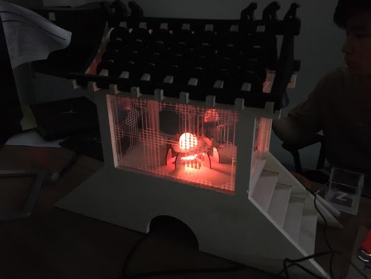
My output device is Humidifier (Grove - Water Atomization)
Device that dissolves water into smoke by ultrasonic waves
[Information of grove - water atomization]
Specifications
- Parameter Value
- Operating Voltage 5.0V(DC)
- Ripple(at Max power) ≤100 mV
- Max power 2W
- Peak output voltage 65±5V
- Operating frequency 105±5kHz
- Chips ETA1617, NE555
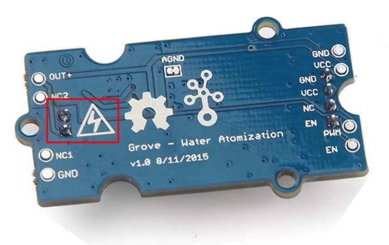
The inductor L2 (marked in red rectangle above) will be heated. So do not touch it directly
Do not touch transducer interface pins directly because peak output voltage of Drier board can be 65V
Place the soldering side up
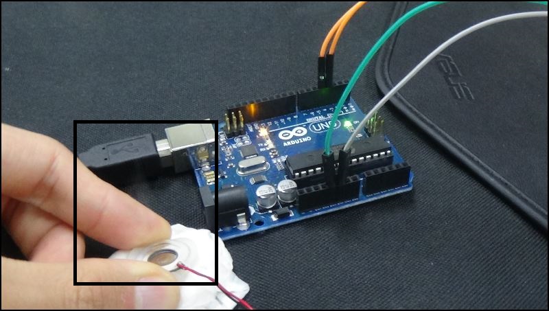
Simple test using the Arduino Uno Board
I used the Attiny 1614 board made in the 9th week
Week 9 Link
This board is designed to operate the humidifier according to the value of the dust sensor
The code below is the sample code in the tutorial that only changed the pin number
// the setup function runs once when you press reset or power the board
void setup() {
    // initialize digital pin 13 as an output.
    pinMode(8, OUTPUT);// Set A5 as OUTPUT

}

// the loop function runs over and over again forever
void loop() {


    {
        /* code */
        digitalWrite(8, HIGH);   // atomize
        delay(10000);              // wait for 10 seconds
        digitalWrite(8, LOW);    // atomization stopped

    }
}
This code only turns it on using pin 8 because it does not need to be re-valued from the humidifier sensor
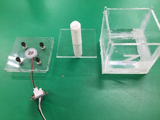
And using acrylic and laser cutter 3D printer, I made a part that could deliver water to my humidifier
Inside the filter, it's a fabric for embroidery
This Week Hero Video!
File Filter.stl
Acrylicbox.ai
Code.ino
After the Academy closed, I knew that the homework for Outputer was done on the Arduino board,
and later I tried to add a document, but I lost the board that connects the humidifier with my board.
Unfortunately, I will re-document the LED control using the board I designed.
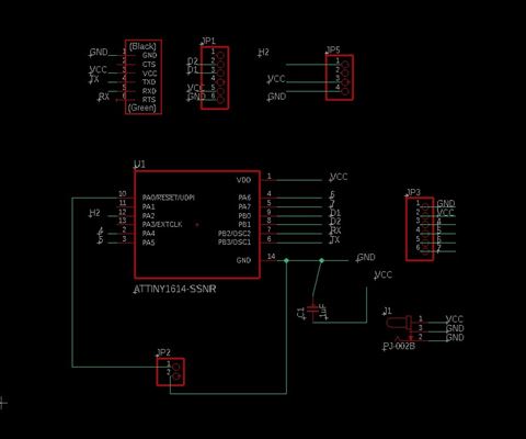
This is the atiny1614 board used in the final project.
You can find out more about this board through this link
I redesigned the LED components that I don't need to control
This link will show you how to design and export your board using an EagleCad
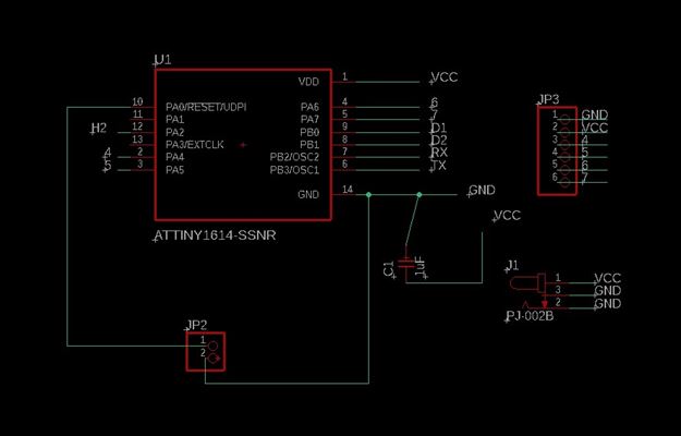
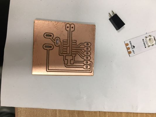
Completed Circuit Diagram Shape
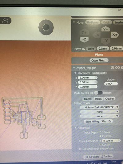
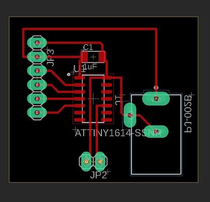
I gave him a clearance of 0.5mm for comfortable lead, and it took about 40 minutes for milling
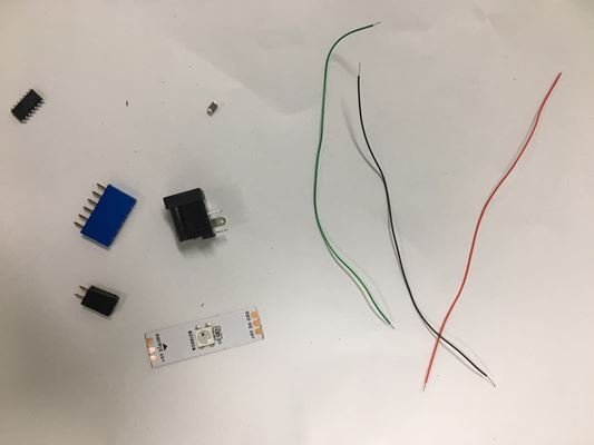
The components were pre-arranged during milling.
Atiny1614
6pinheader (for LED)
2pinheader (for UPDI)
1uF C
LED
For more information, please refer to the NeoPixel Library LINK
You must receive a neopixel library to use the arduino example code
I made a mistake using the bantam in about four months.
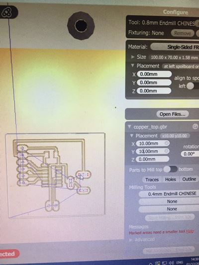
After a few modifications to the design, I forgot to give a tolerance of about 3mm from the origin
If you look at the picture above, you can see that the x- and y-axes are given a tolerance of 6mm.
Mistakes that appear if tolerance is zero
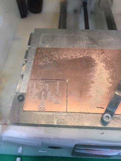
It's a waste to rebuild the board, so I cut it with a saw(After the Academy, I learned that I had to continue to review)
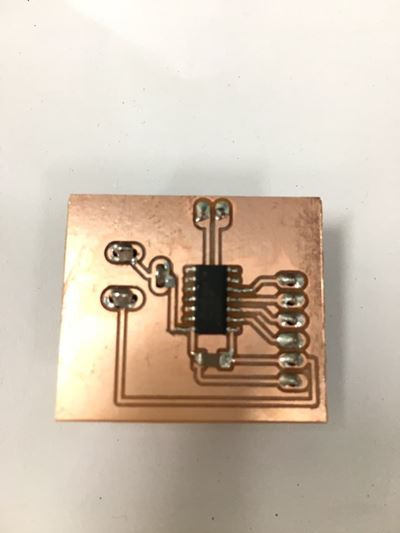
I was a little short of solder because I was in a hurry, but I was able to save a lot of time and solder
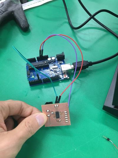
I used Arduino Uno Board as an UPDI programmer to code my board.
You can find out about UPDI programming by checking my week8 embedded programming week LINK
#define HYUNHOLEDPIN 0
#define NUMPIXELS 1
#define DELAYVAL 500
void setup() {
#if defined(__AVR_ATtiny85__) && (F_CPU == 16000000)
  clock_prescale_set(clock_div_1);
#endif


  pixels.begin();
}

void loop() {
  pixels.clear();


  for(int i=0; i<NUMPIXELS; i++) {


    pixels.setPixelColor(i, pixels.Color(0, 150, 0)); //my favorite color green

    pixels.show();

    delay(DELAYVAL);
  }
}
This is my code
I referred to the example code of NeoPixel
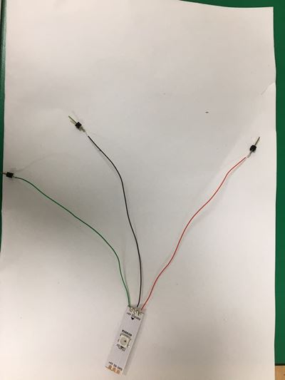
At the top is the pin number that connects my Attiny1614 and red.
Second, set the number of leads.
The three numbers next to the pixel color represent each RGB.
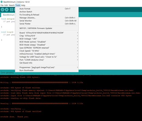
I check the chip and clock speed, and I put the green-lighted code on my ATINY1614 board
Burn the bootroder before programming
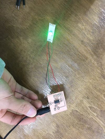
Complete! This Week's Hero Shot!
File
Attiny1614 board.sch
Attiny1614 board.brd
LED code.ino