SAMD11 Dual Serial Programmer
I needed a UDPI programmer for my Embedded Programming assignment. Quentin Bolsee to the rescue, with his dual serial programmer that can do UDPI and serial programming at the same time! SAMD11 dual serial, by quentin-bolsee
KiCad
Quentin supplied native KiCad files and they extracted into a nice folder named d11c_dual_cdc_kicad. This allowed me to open the files and export them as SVG to clean up in Inkscape and then bring those files int the free version of Carbide Create CAM software for creating tool paths for the Nomad 3 milling machine.
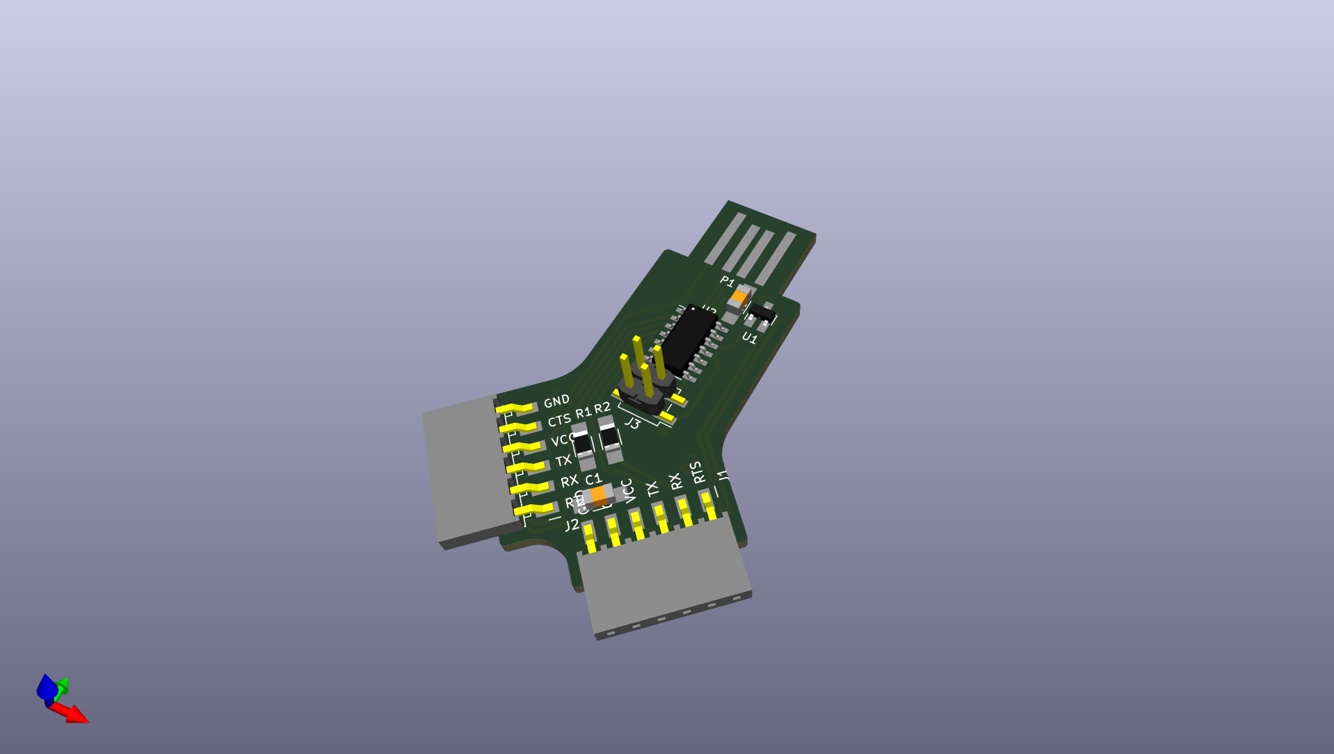
Above: Quentin’s SAMD11 Dual Serial Programmer 3D View in KiCad! I added the 3D cad models so all parts are shown.
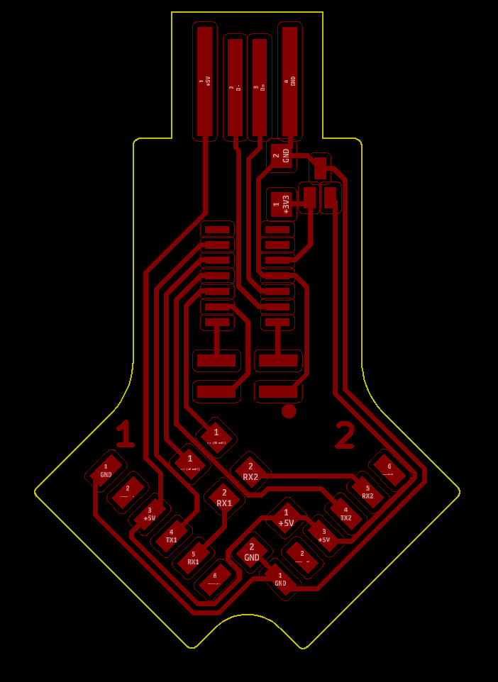
Above: Board ready for sVG export from KiCad
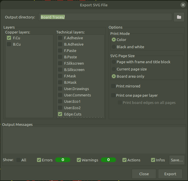
Above: KiCad settings to export SVG.
SVG Cleanup
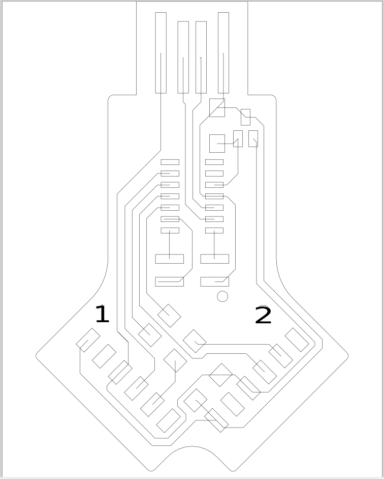
Above: My SVG outputs from Quentin’s KiCad files opened in Inkscape
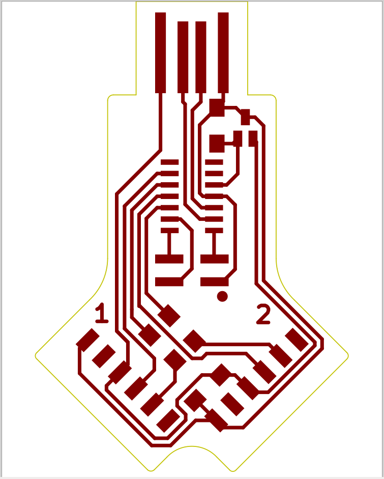
Above: I used my guide here to clean up traces in inkscape quickly.
CAM
Carbide Create CAM steps and settings for the Nomad 3
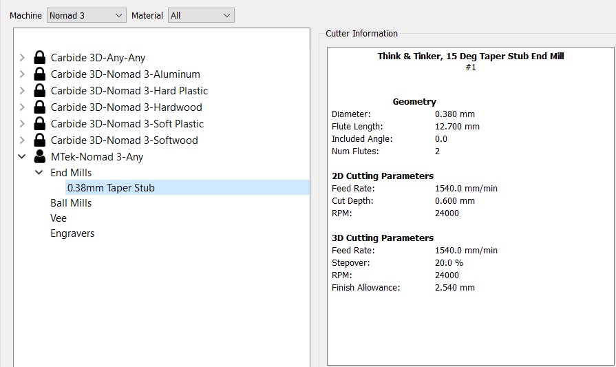
Above: I opened the cleaned up SVG in Carbide Create CAM and setup my Taper Stub End mill with a .38mm tip as show above.
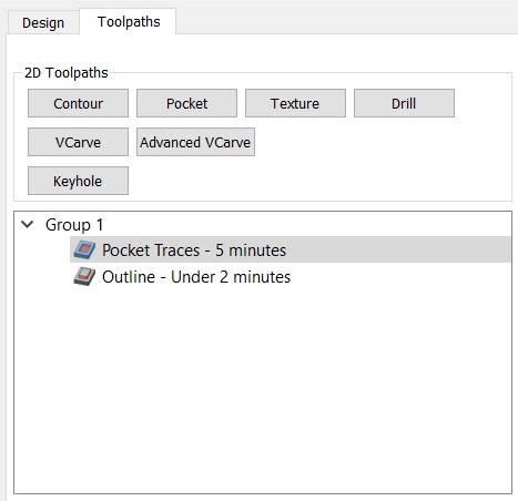
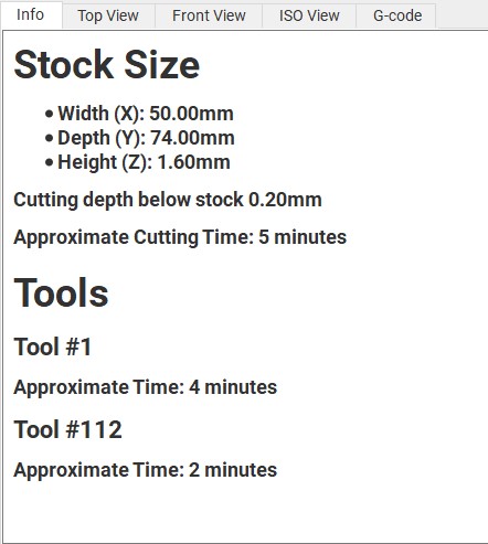
Above: Two toolpaths were setup, one for the Traces and the 0.38mm diameter taper stub end mill and the Outline toolpath using a 1.6mm (1/16”) diameter end mill to cut the board out.
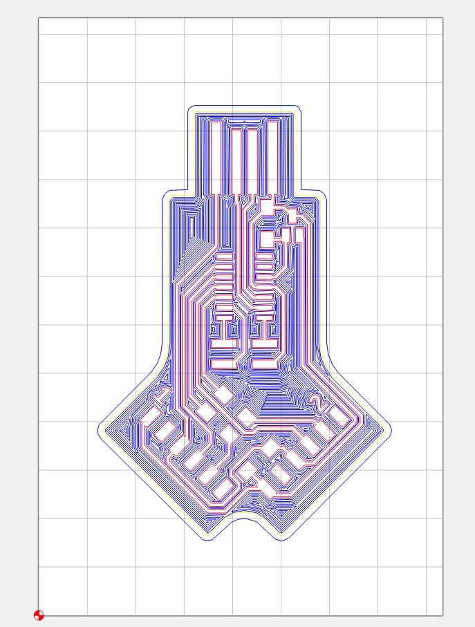
Above: Top view of all 2d toolpaths
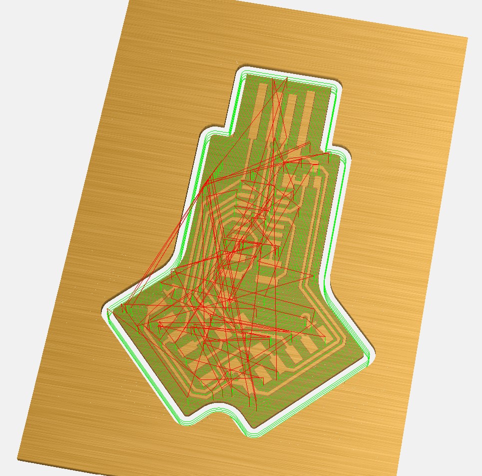
Above: 3D view of material and 3D toolpaths
CNC Milling
I used the Cabide Motion G-Code sender software to make final checks of the actual g-code being sent to GRBL based controller on the Nomad3 CNC Mill.
Above: Next I opened the Carbide Create file in Carbide Motion (the Carbide Create files can be set to contain the g-code)

Above: Here I am checking the g-code in 3D, it looks good, with no errors sending the end mill down in to the mills table for example.

Above: Here I am checking the g-code in 2D side view to make sure the z moves only go barely through bellow the bottom of the material for cut out, and that the traces are milled slightly through the surface of the material.
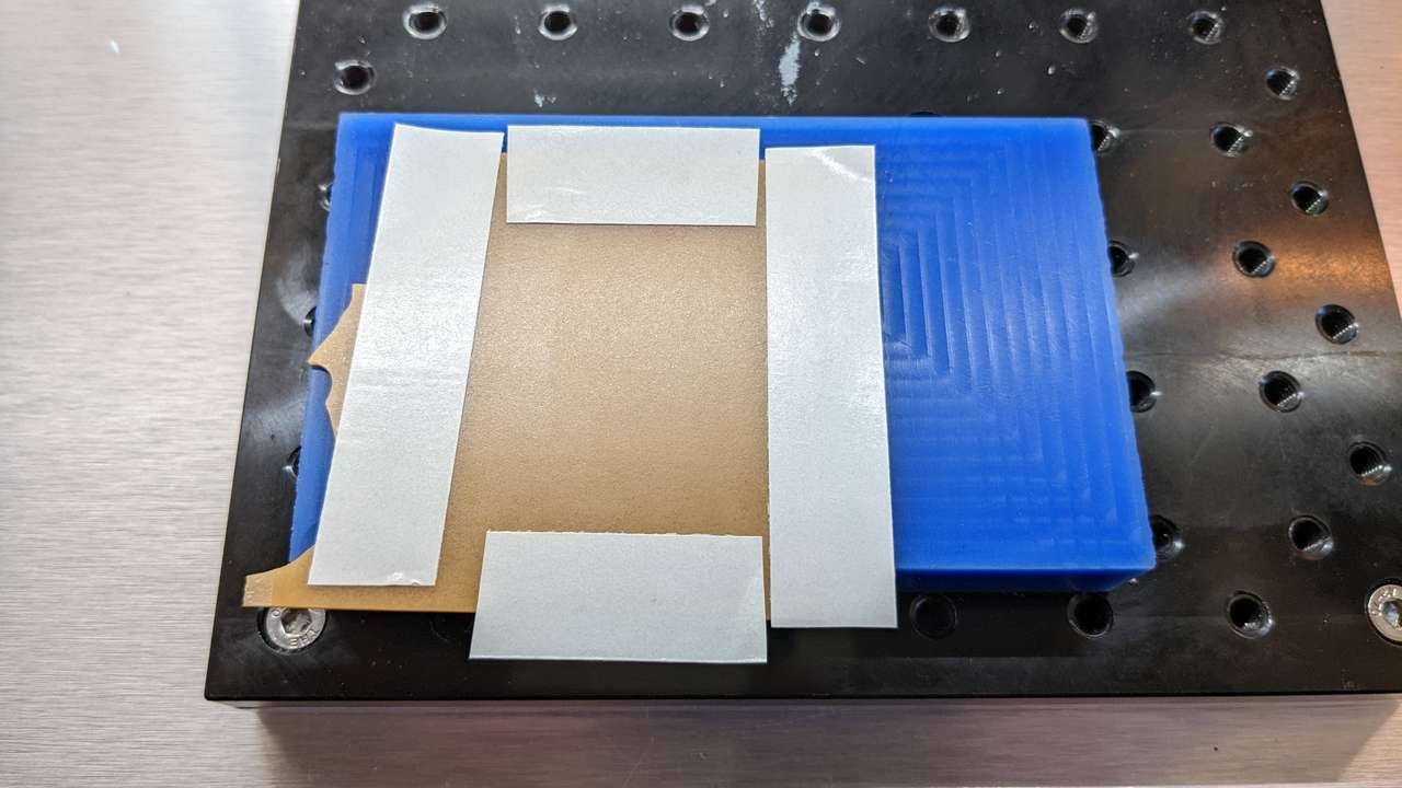
Above: I put the Shuretape DF 65 around the perimeter of the area where the board would be milled to prevent gumming up the end mill when cutting the outline of the board out.
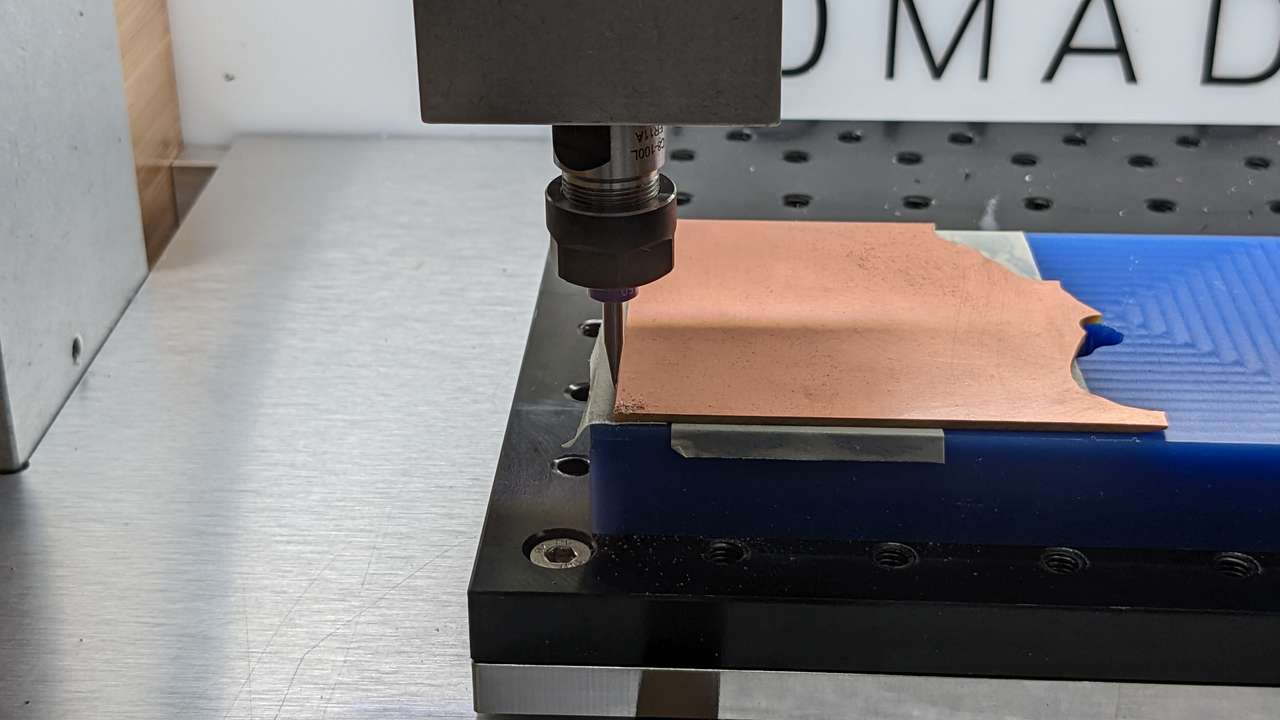
Above: I touched the 0.38mm diameter taper stub end mill on the surface of the FR1 circuit board blank with the spindle running. I did not use the z zero touch plate, since it may break or chip the tiny end mill. I zeroed the x,y, and z axis in the lower left corner of the FR1 circuit board blank, using the Carbide Motion software.
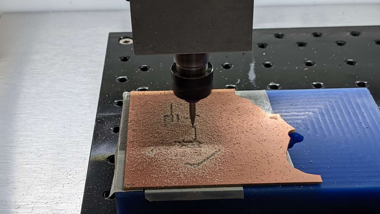
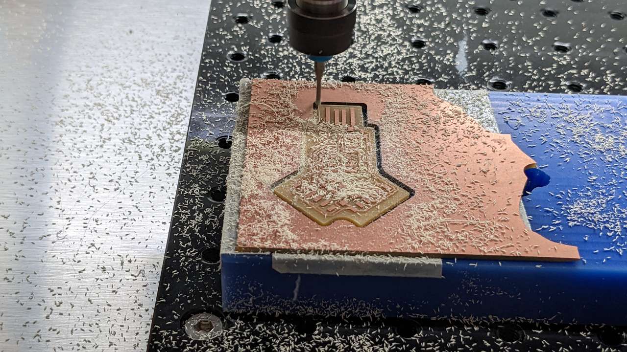
Above: Milling starts! The traces and pocket clearing took about 6 minutes to mill. Pocket clearing is not necessary, but since I am the only user of the mill at home, I can take the extra time to do it. Pocket clearing also helps prevent solder bridges on small board like this one during the soldering process, especially since I am getting older and can’t see as well.
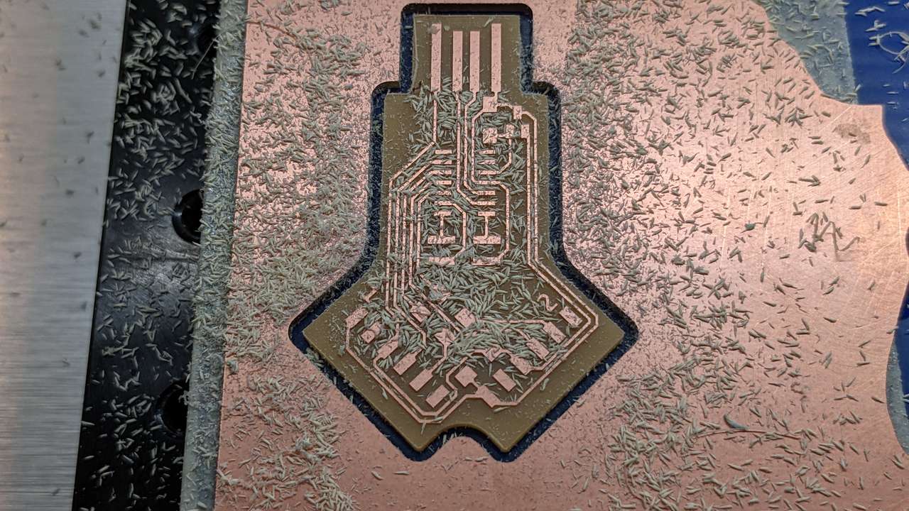
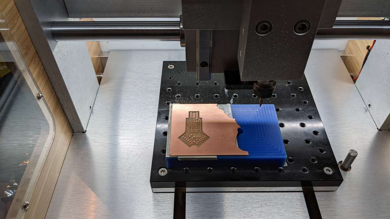 Above: Traces done and chips vacuumed up.
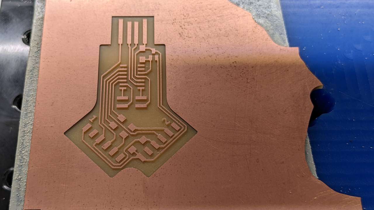
Above: Close up of traces and milled pockets. Time to change to 1.6mm diameter end mill to cut out the board!
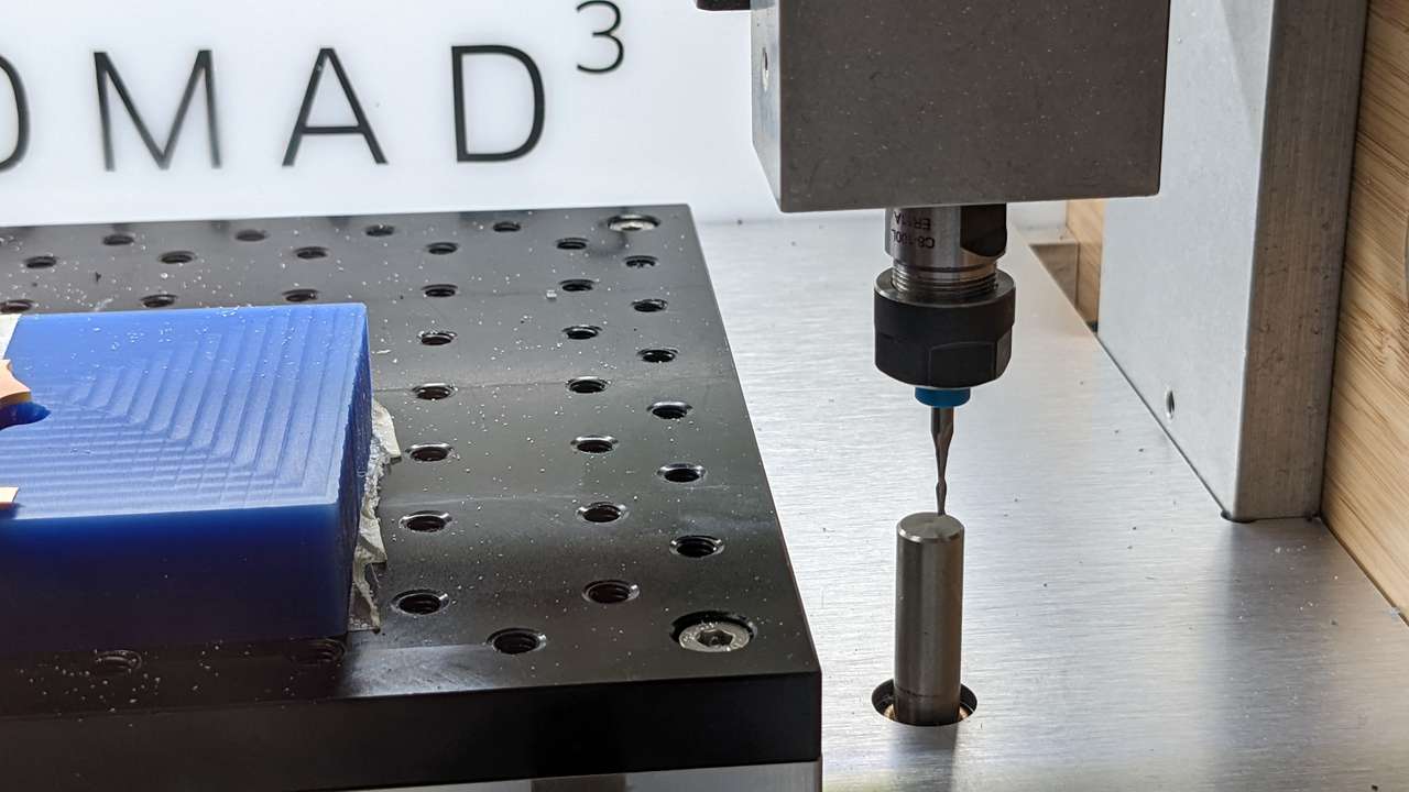
Above: 1.6mm diameter end mill being probed for automatic Z offset. The z probe is very gentle and even the very small tapered stub end mills can be probed.
Above: Board outline being milled.
Above: Board cutout with chips.
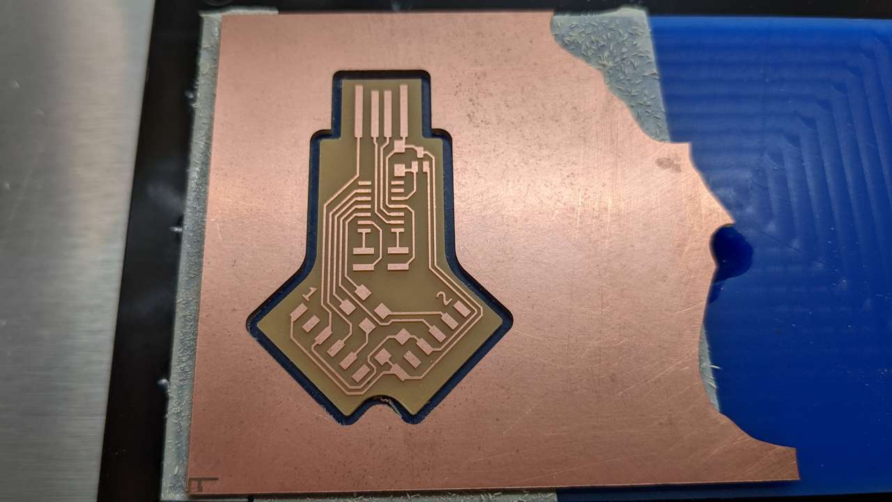
Above: Board cutout clean.
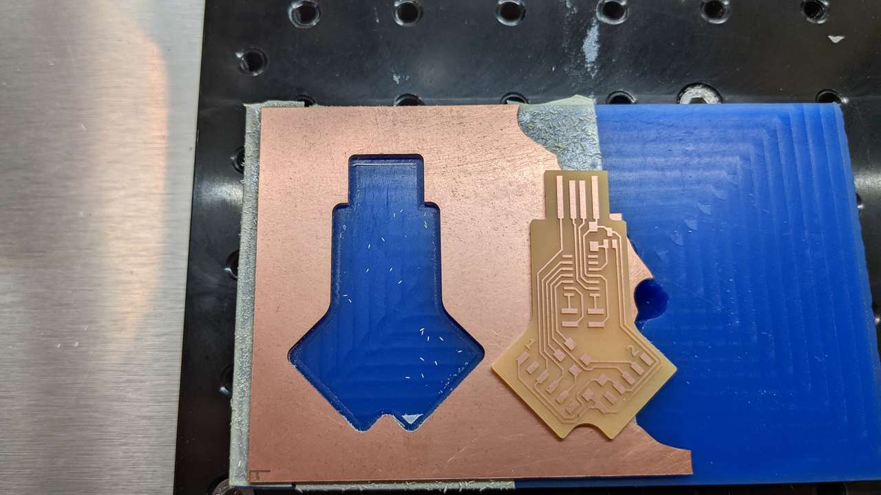
Above: The board popped right out, only one small bit of tape was milled.
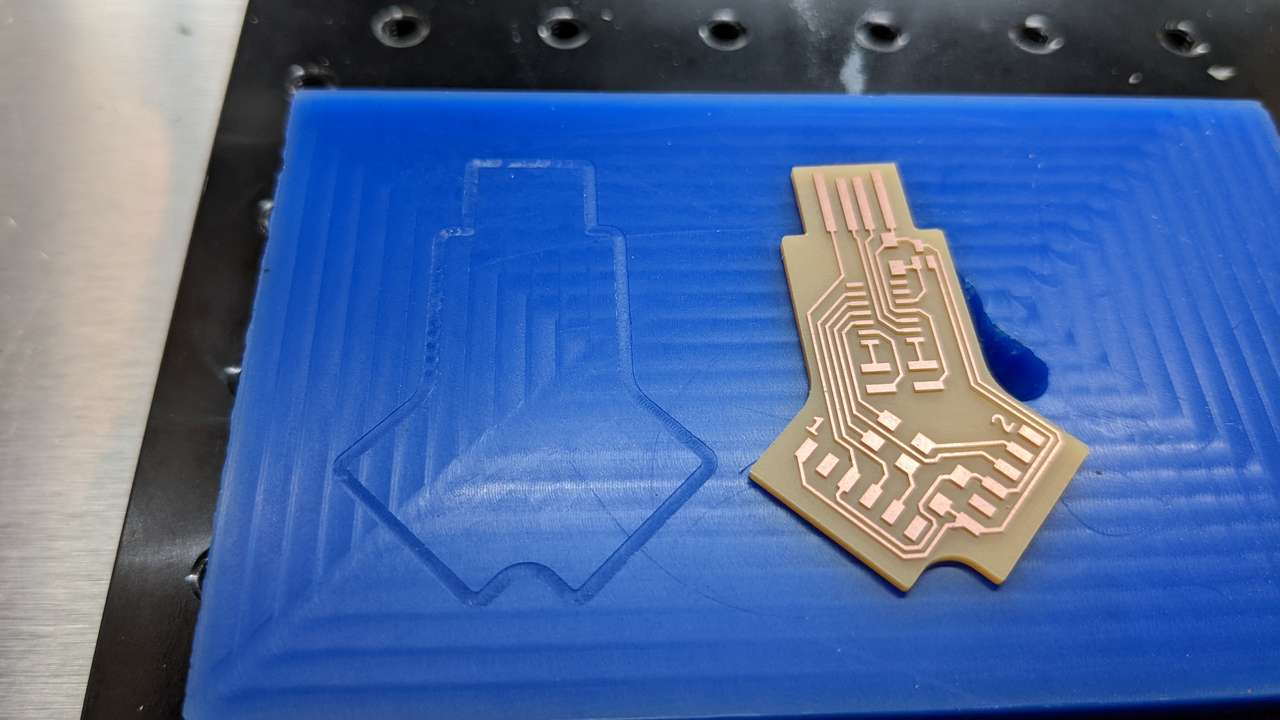
Above: The cutout milling left only a very slight witness in the machinable wax base.
Interactive Html BOM
I exported the Interactive Html BOM (iBom) to help me manually pick and place components.
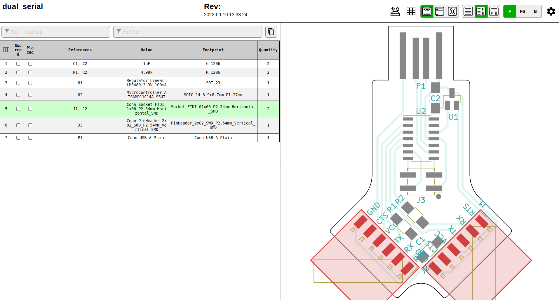
Above: Click image to access the HTML Interactive BOM (iBOM) generated by KiCad.
I printed the iBOM and out some clear double stick tape on it. Then I selected the components from my Stanley bins stuck them on the printed iBOM.
Stuffing
Programming Firmware
I found a way to add EDBG to linux on the MIT CBA MTM webiste: EDBG Since I run Linux Mint I did the following:
Install Dependency:
sudo apt update
sudo apt install libudev-dev
Then I got the latest binary of EDGB via the link under Installation
In case you haven’t run binaries on Linux before, after downloading .bin file are not executable by default for security reasons. You need to change the permissions on the file to do that. I like to use the file navigator GUI of Linux Mint to do this. Press windows key + e to open the file navigator and find your bin file, right click it, go to the permissions tab and check the “Allow executing file as program” box. close the window.
I also like to strip off any version info off the binary file for example edbg-linux-r44 to edbg
Now move the .bin file to /usr/bin this is where most Linux systems have executable binaries. You’ll need to open the folder /usr/bin as root to do this so once you navigate to /usr/bin right click on the background of the file navigator window and click open as root. Now copy or move the .bin file here. Right click on the background of the file navigator window and select open in terminal. To run the EDGB binary file type:
name_of_file in my case it was edbg since the file is in the /usr/bin folder you can run it from anywhere in terminal.
./binary_name
./edbg
Now I continued along with quentin-bolsee’s instructions.
I downloaded his compiled binary compiled binary: dual_cdc_d11.bin
Next I plugged my new SAMD11 dual serial board in a USB port and open a terminal window and ran:
edbg -ebpv -t samd11 -f dual_cdc_d11.bin
and I got an error: “Error: no debuggers found” hmmmm
How do install debuggers that edbg needs?
I decided I needed help and I e-mailed Quentin:
While waiting for an e-mail back from Quentin, I did some more searching about alternative firmware for the MAX32625PICO.
I did a google search for “fab academy use “MAX32625PICO”” and on of the links that came up talked about how to setup a MAX32625PICO for programming fab academy boards:
https://fabacademy.org/2021/labs/kannai/instruction/tips/fa2022_embed_env/#max32625pico
Here is the section that helped me the most:
```Hold down the button while connecting the board to your computers USB port. A drive named “MAINTENANCE” will appear.
Download max32625pico_daplink.bin default DAPLink image
Save the program binary file to your MAINTENANCE Microcontroller Disk, just like you would with a normal USB disk
disconnected and reconnected, the board will appear as a drive named “DAPLINK”```
I did the above and tried my command again
edbg -ebpv -t samd11 -f dual_cdc_d11.bin
and the same error appeared?
Debugger: ARM DAPLink CMSIS-DAP 04090000e4b40cb200000000000000000000000097969906 1.0 (S)
Clock frequency: 16.0 MHz
Error: invalid response during transfer (count = 0/1, status = 7)
What am I doing wrong?
I give up for tonight. 2022-Oct-6
I hope I can get my boards programmed this weekend!
Did I miss some documentation in class? Let’s look, i went to embedded programming and searched at: https://fabacademy.org/2022/
The only thing I found was: https://fab.cba.mit.edu/classes/863.20/CBA/people/davepreiss/weeks/09.html
Well I looked at the datasheet for the SAMD11C chip after asking Quentin what was wrong. Embarrassing! And a debugger is programmer and debugger physical hardware board. It ends up I luckily had one that would work the MAX32625PICO! And sure enough the MAX32625PICO data sheet says on page 3:
Loading and Debugging Applications The MAX32625 is programmed at the factory with a bootloader and DAPLink application firmware loaded so that it can be used out of the box as programming/debug adapter for other boards.
So plugged the MAX32625PICO into my USB port and ran the command:
And ran the command:
lsusb
and got the reponse:
“Bus 003 Device 008: ID 0d28:0204 NXP ARM mbed”
edbg -ebpv -t samd11 -f dual_cdc_d11.bin
and got the response!:
“Debugger: ARM DAPLink CMSIS-DAP 04090000e4b40cb200000000000000000000000097969906 1.0 (S) Clock frequency: 16.0 MHz Error: invalid response during transfer (count = 0/1, status = 7)”
Sweet! Now to wire the MAX32625PICO up to the 4 pins of the SAMD11 Dual Serial Programmer
Adapter Board
I decide to make a small 10 pin 1.27 pitch to 10 pm 2.0 pitch adapter board to program the SAMD11C. I have the MAX32625PICO debugger and programmer it costs about $15 so it is much more affordable than the ATMEL ICE at $180 for programming ARM® Cortex®-M0+ like the SAMD11C.
So I quickly designed an adapter board in KiCad called the PrgAdapt10.
Programming Firmware 2
I needed EDBG so I followed the Linux install instructions here: https://mtm.cba.mit.edu/2021/2021-10_microcontroller-primer/edbg/
First I needed to meet the libudev-dev dependency:
sudo apt update
sudo apt install libudev-dev
Then I downloaded https://mtm.cba.mit.edu/2021/2021-10_microcontroller-primer/edbg/edbg-linux.zip
Got the response:
edbg -ebpv -t samd11 -f dual_cdc_d11.bin Debugger: ARM DAPLink CMSIS-DAP 04090000e4b40cb200000000000000000000000097969906 1.0 (S) Clock frequency: 16.0 MHz Error: invalid response during transfer (count = 0/1, status = 7)
I searched the internets to see if I could find out how to correct this error. I didn’t find a solution I could understand :(
I decide to e-mail Quentin the error above.
While waiting, I contacted Alan Han and asked him if he had a programmer. He did, actually an ATMEL ICE that I had forgotten I had borrowed to him. Alan dropped the ICE off at my place and I tried it out.
I used the Atmel-ICE User Guide to guide me in the correct connections to program my board.
Using the pinouts on page 28 section 4.2.4. I matched the ATMEL-ICE pins of the SAM port to the GND,DIO,RES,CLK pins of the 4pin SAMD11DualSerial Board. Conveniently the pins on the adapter board I made matched the pins being used! I plugged the ICE Ribbon cable to the adapter board and then jumped the pins to the SAMD11DualSerial Board 4 pin JTAG programming pins.
I ran the edbg command to program again:
edbg -ebpv -t samd11 -f dual_cdc_d11.bin
and got the response:
Debugger: ATMEL Atmel-ICE CMSIS-DAP J42700007665 1.0 (SJ)
Clock frequency: 16.0 MHz
Error: invalid response during transfer (count = 0/1, status = 0)
Shit! Time to learn more I am obviously not understanding what I am doing here :)
I spent a few hours learning about JTAG and different programmers, and I also came across the Open On-Chip Debugger OpenOCD. Then I found this video which really helped me out!
How to: SAMD Video Tutorial!
Finally I found a single resource to learn how to program SAMD chips. I am not sure how I missed this Fab Academy bootcamp video previously!
Fab Academy 2021: SAMD microcontrollers and guess what Quentin Bolsée and Nicolas De Coster. This video explained in detail the small steps I needed to know about programming and using SAMD microcontrollers
Another e-mail from Quentin
Error: invalid response during transfer (count = 0/1, status = 7): This usually means that there is a communication issue with the target. You could triple check the connection, Yep my wiring was wrong for the ATMEL ICE! Triple checking the wiring I found out that I had DIO wrong! I figured this out by opening up the ice and tracing pins using the datasheet and my multimeter. My convert board was labeled “TGT RX” instead of “DIO”. also make sure that the target gets an adequate 3.3V from its regulator. I measured 3.32 vdc, looks good!
I wonder if I had the same wrong wiring pin issue when using the MAX32625PICO programmer / debugger?
I ran the edbg command to program again:
edbg -ebpv -t samd11 -f dual_cdc_d11.bin
and got the response:
Debugger: ATMEL Atmel-ICE CMSIS-DAP J42700007665 1.0 (SJ) Clock frequency: 16.0 MHz Error: invalid response during transfer (count = 0/1, status = 0)
Shoot, what am I doing wrong?
I’ll try the MAX32625PICO programmer again:
edbg -ebpv -t samd11 -f dual_cdc_d11.bin
Debugger: ARM DAPLink CMSIS-DAP 04090000e4b40cb200000000000000000000000097969906 1.0 (S) Clock frequency: 16.0 MHz Error: invalid response during transfer (count = 0/1, status = 7)
Remote Student Support Ideas
I am realizing now how hard it is tom complete Fab Academy with a local instructor and myself actually together physically in a Fab Lab. The microcontroller topics are way outside my skill set and I need a lot of help. But I will power on remotely. I’d like to be able to establish a way to support remote students in Fab Academy in the future. A time zone based remote support group would probaly work best for most students.
For the hell of it I tried to run the edbg command again:
edbg -ebpv -t samd11 -f dual_cdc_d11.bin
Nope! same error as above :(
I triple checked all my wiring, and ran the command again:
edbg -ebpv -t samd11 -f dual_cdc_d11.bin
And got the same error
Debugger: ATMEL Atmel-ICE CMSIS-DAP J42700007665 1.0 (SJ)
Clock frequency: 16.0 MHz
Error: invalid response during transfer (count = 0/1, status = 0)