12. Output devices
In this week I will make a circuit to host my two output lights “one to tell the rear car how close it is (red ,yellow ,green) with the help of the ultrasonic sensor and the other to show how much breaking is pressed (red) with the help of the accelerometer to serve my final project.
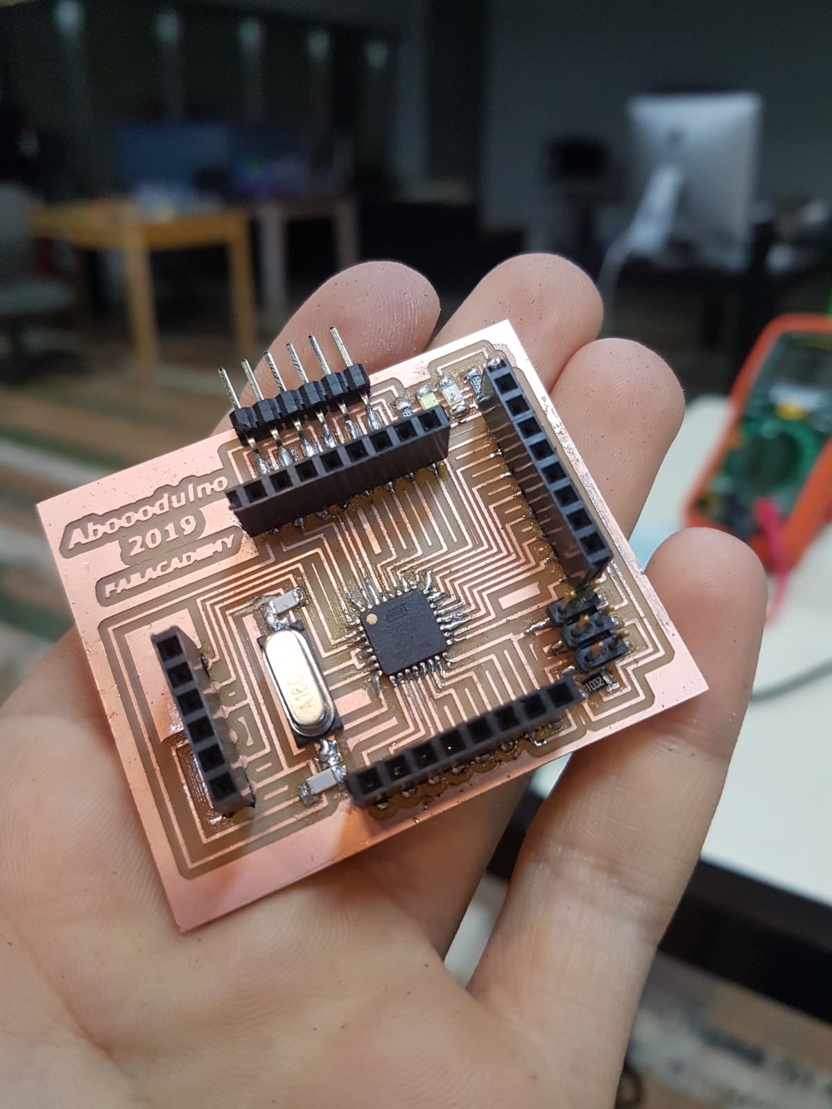
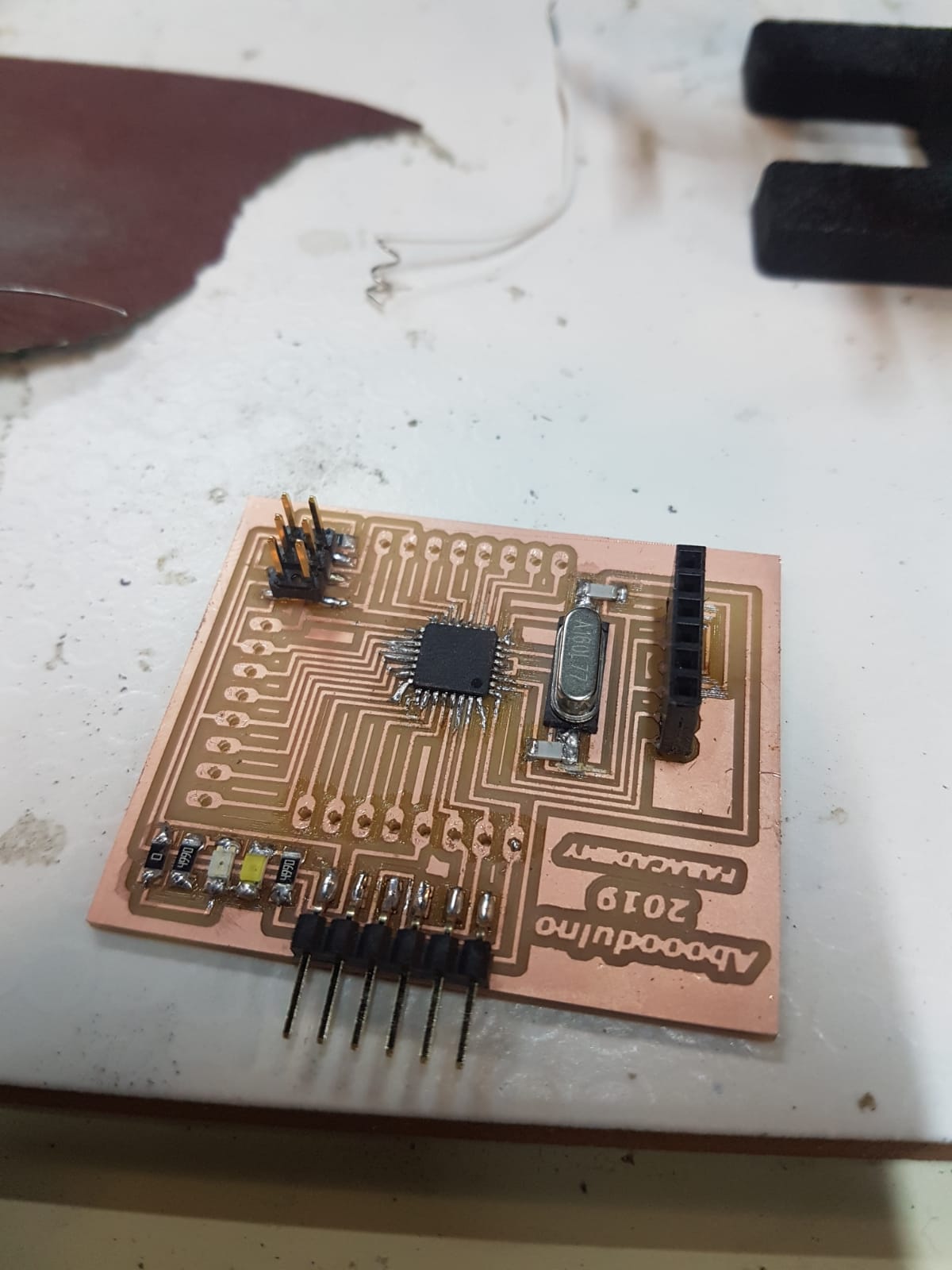
In this week I made a cicuit to host both input and output devices.
Using the same steps mentioned in week5 and the notes from week11 I milled my PCB.
Group Assignment
Design
I started by adding the parts and connevting the oscillator. my stratigy was to connect all the pins to a female header so I can use all the pins available.
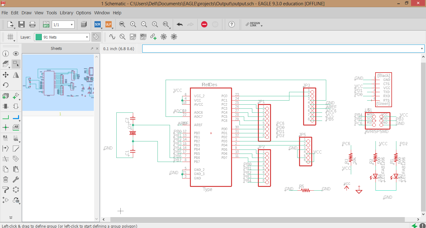
My strategy in orginazing the wires was simple ..> connect all the pins to the female headers then connect the ftdi and the isp header with the power led and digital 2 led.
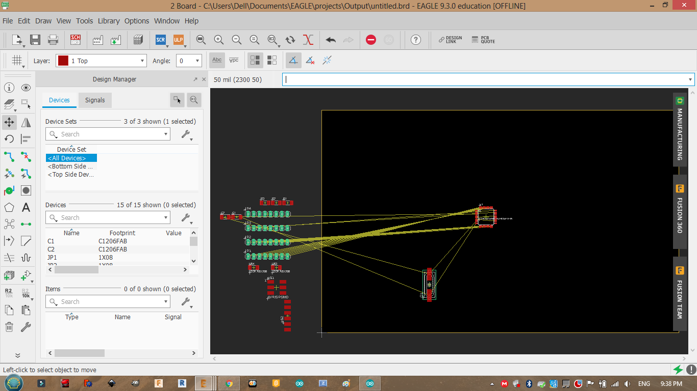
I tryed to make it as small as possible.
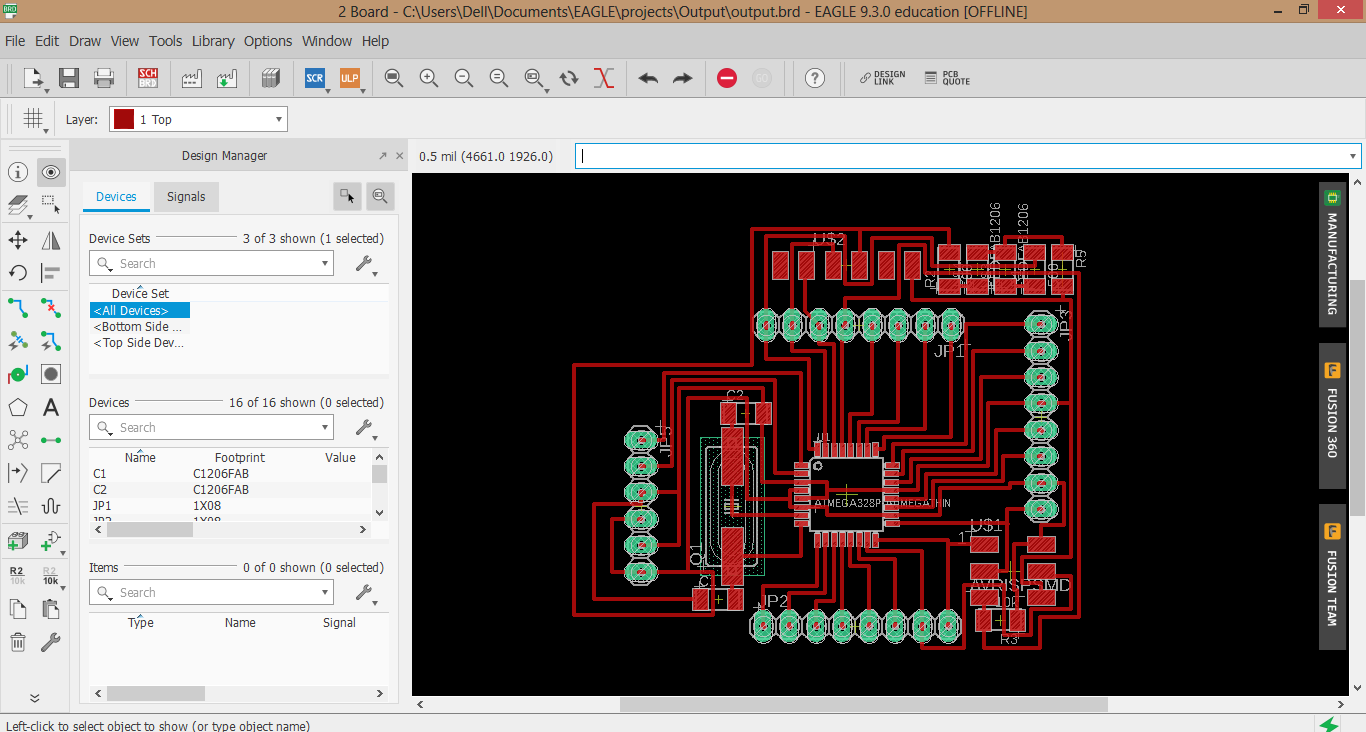
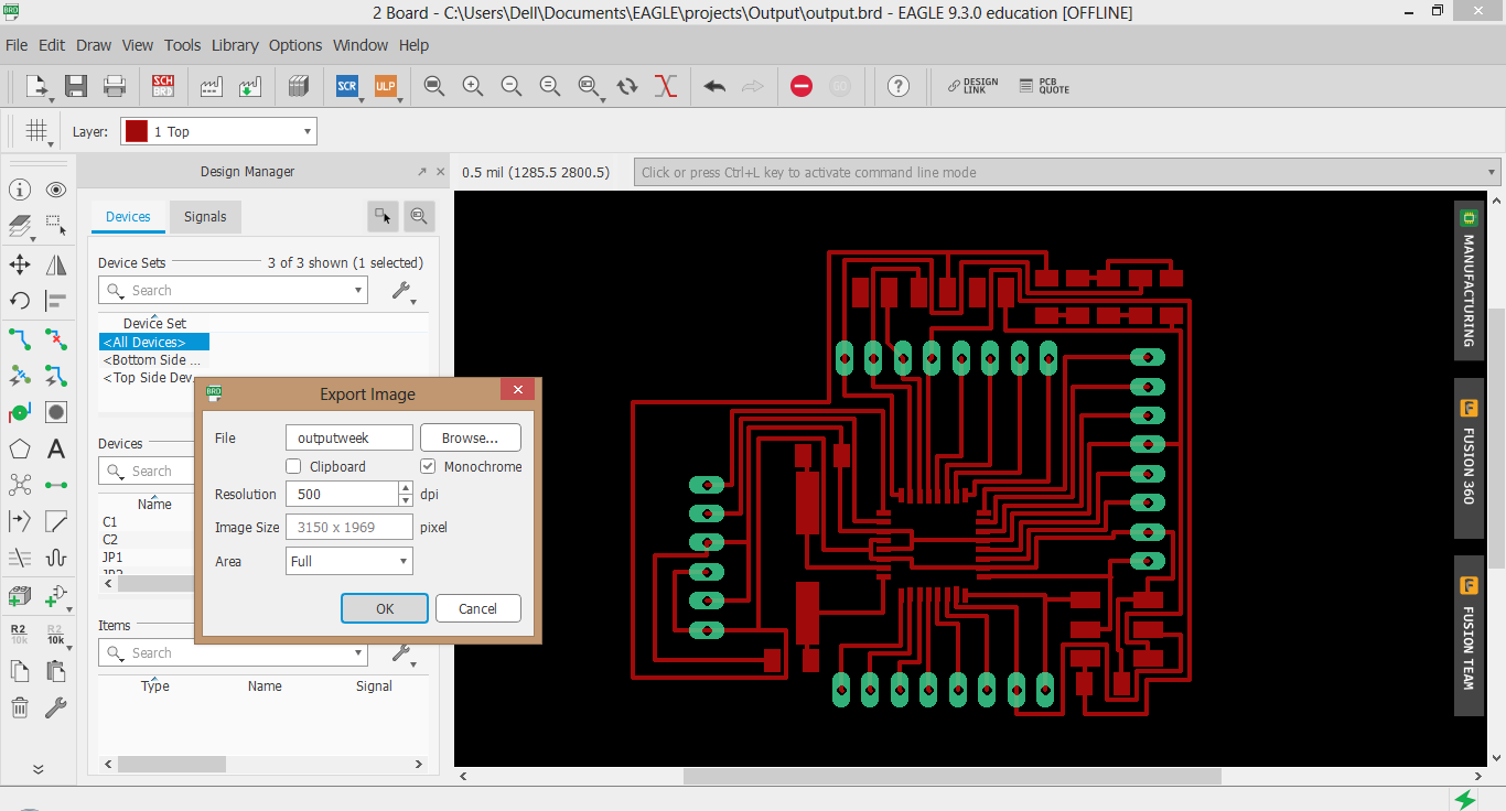
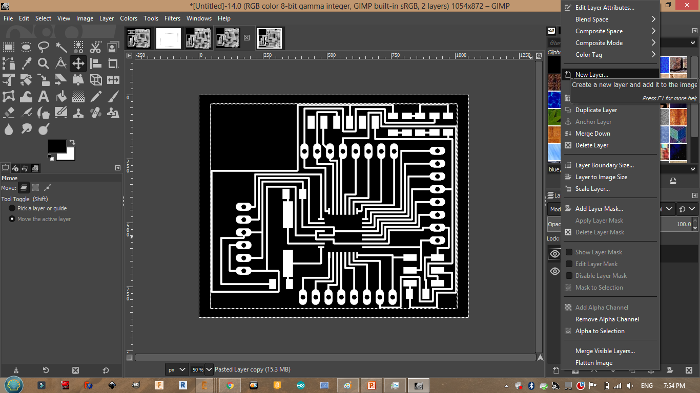
Since I have used a through hole headers I need to show there path so I can mill them. Click on layers.
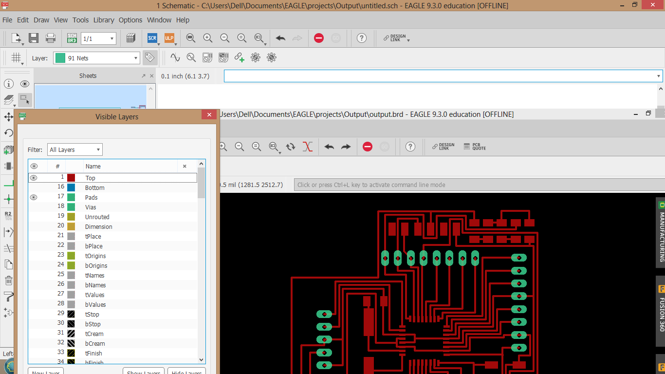
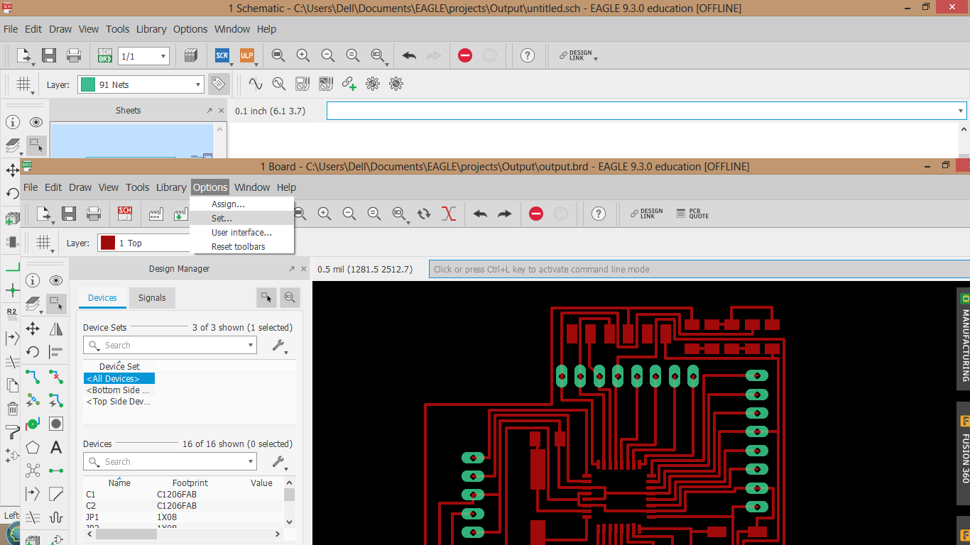
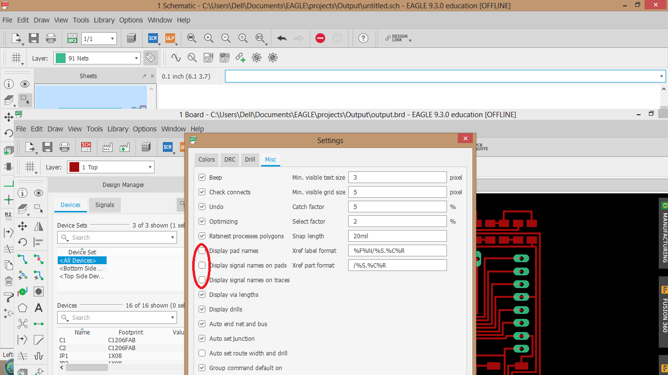
I had to hide the names of the components so they dont show up when exporting the image.
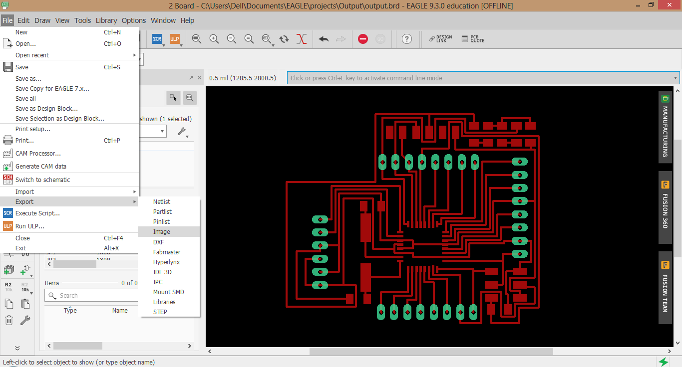
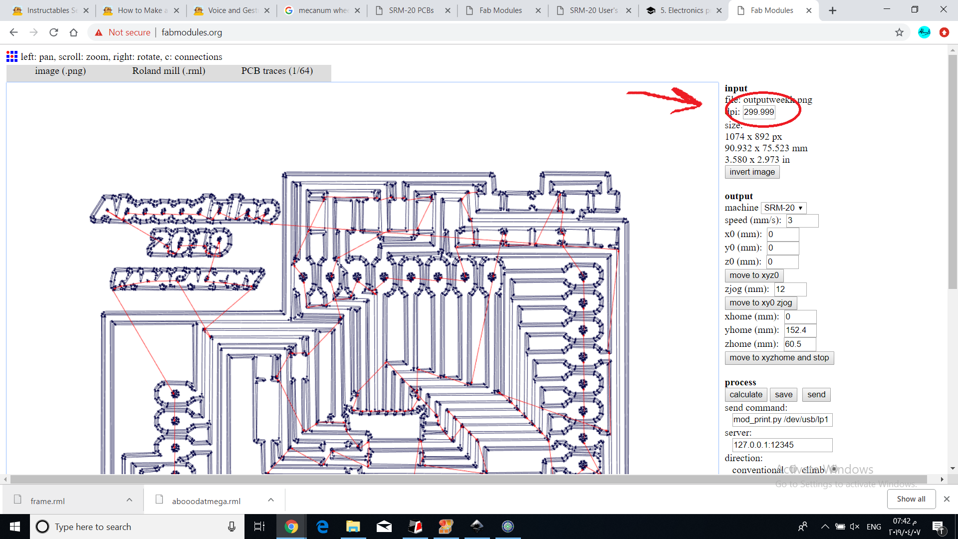
I exported the design make sure 500 dpi and monochrome.
Gimp
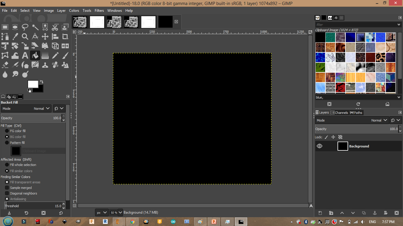
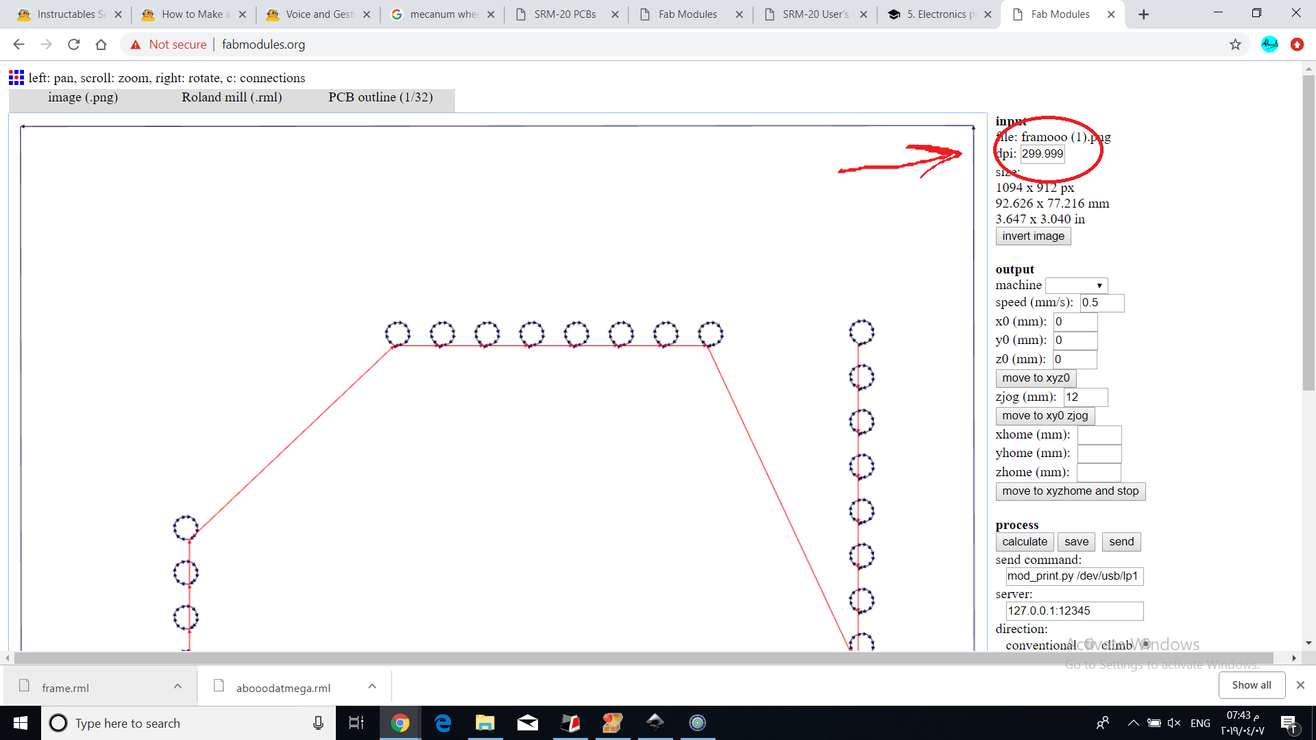
I started making the frame. Note that the frame and the circuit designs has to have the same size.
Crop to content.
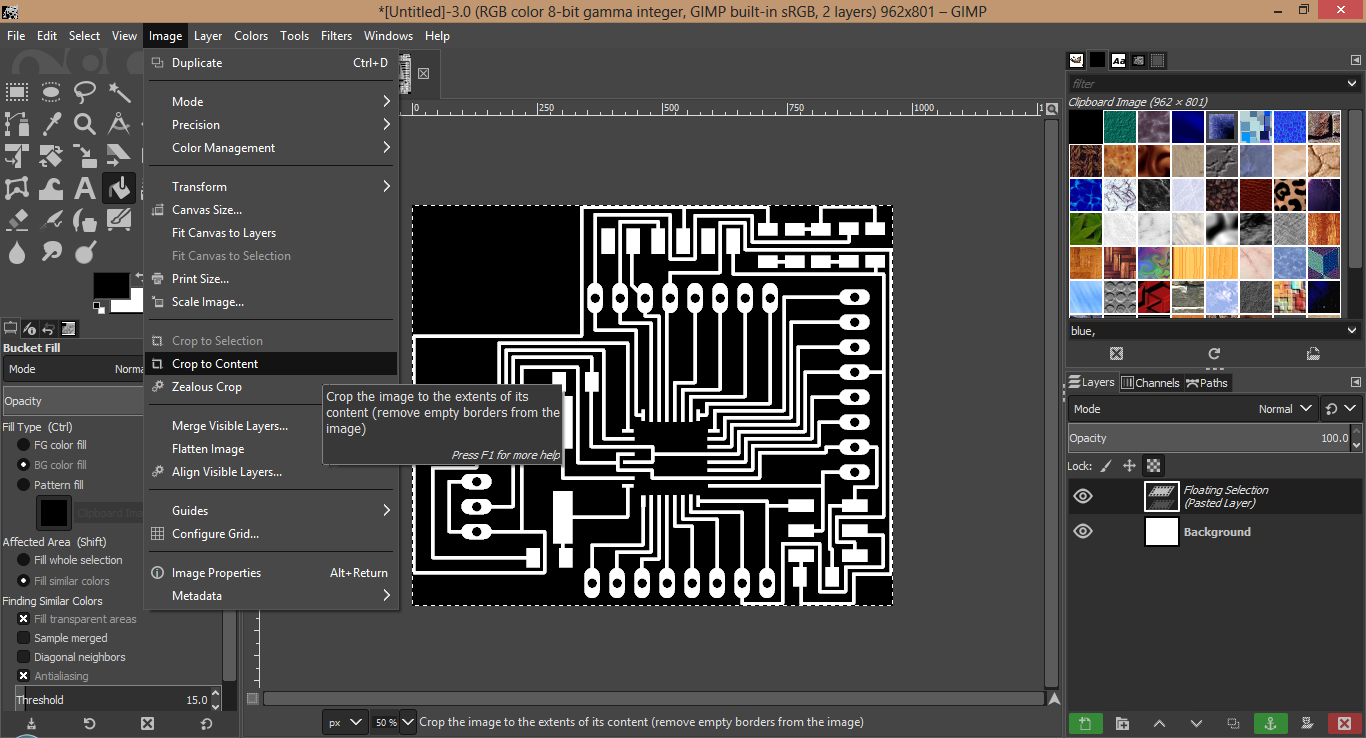
I clicked on creat new image just to see the size of my image so I can add 20px each side.
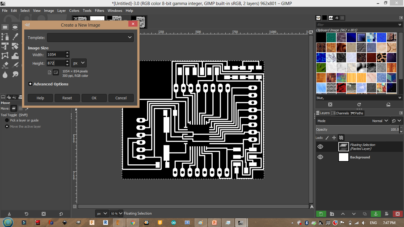
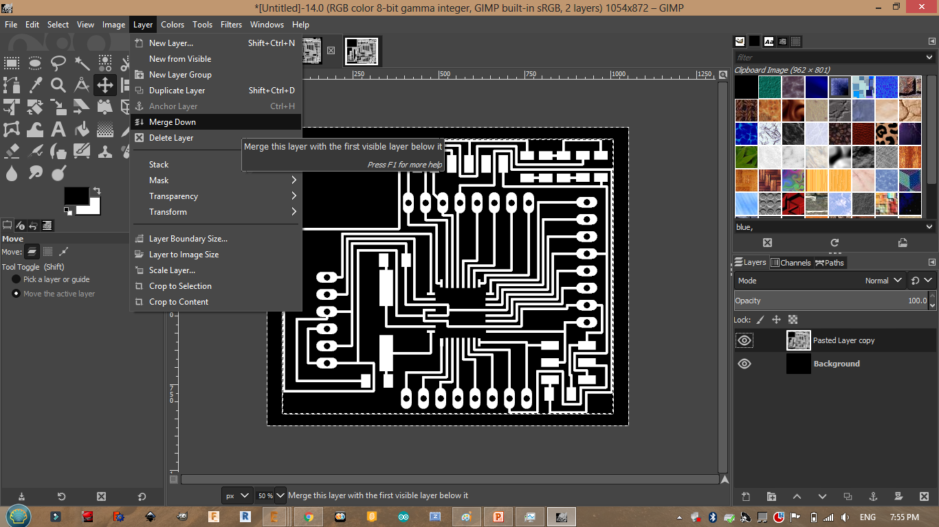
Useful link shows how to merge layers.
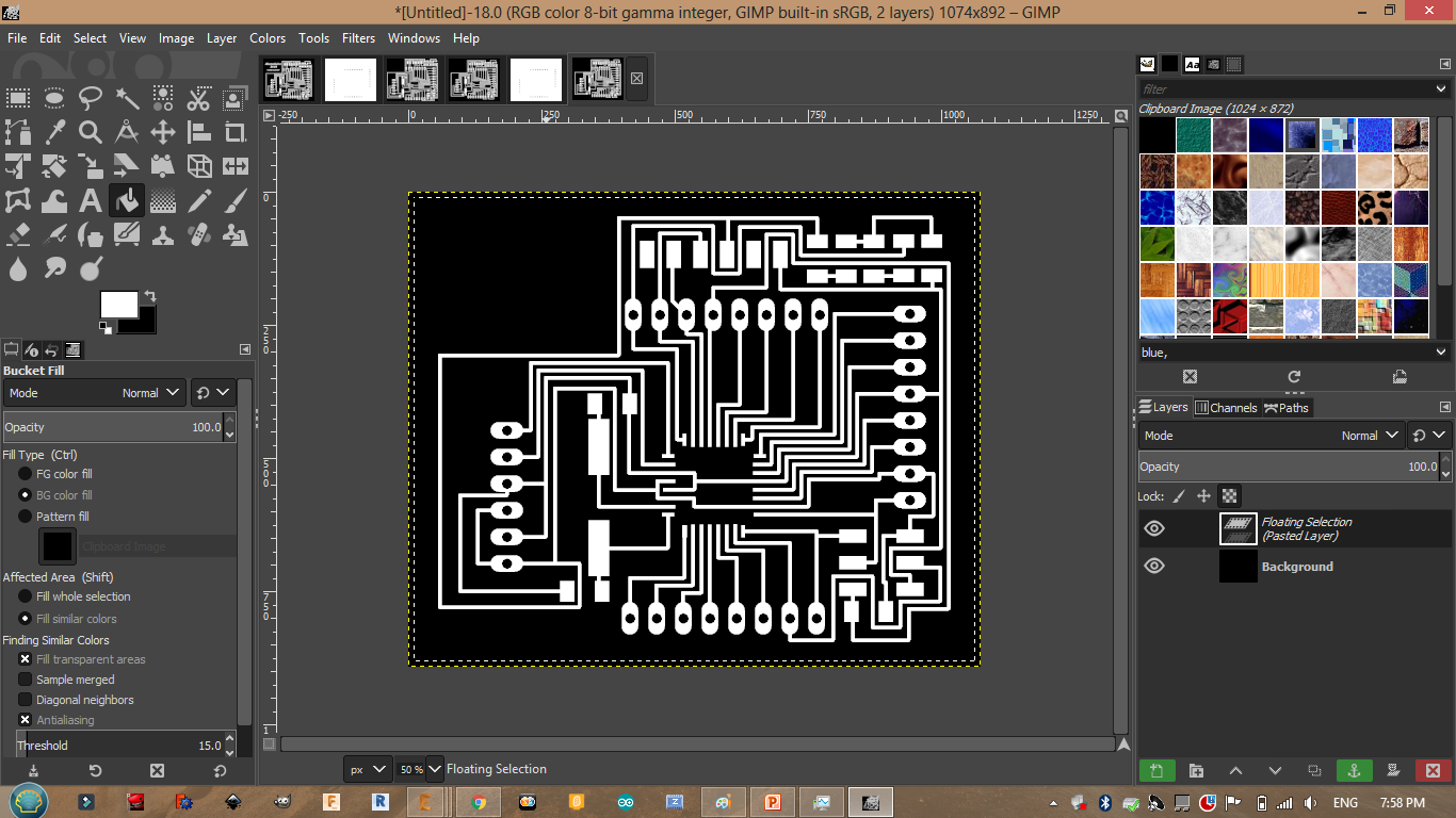
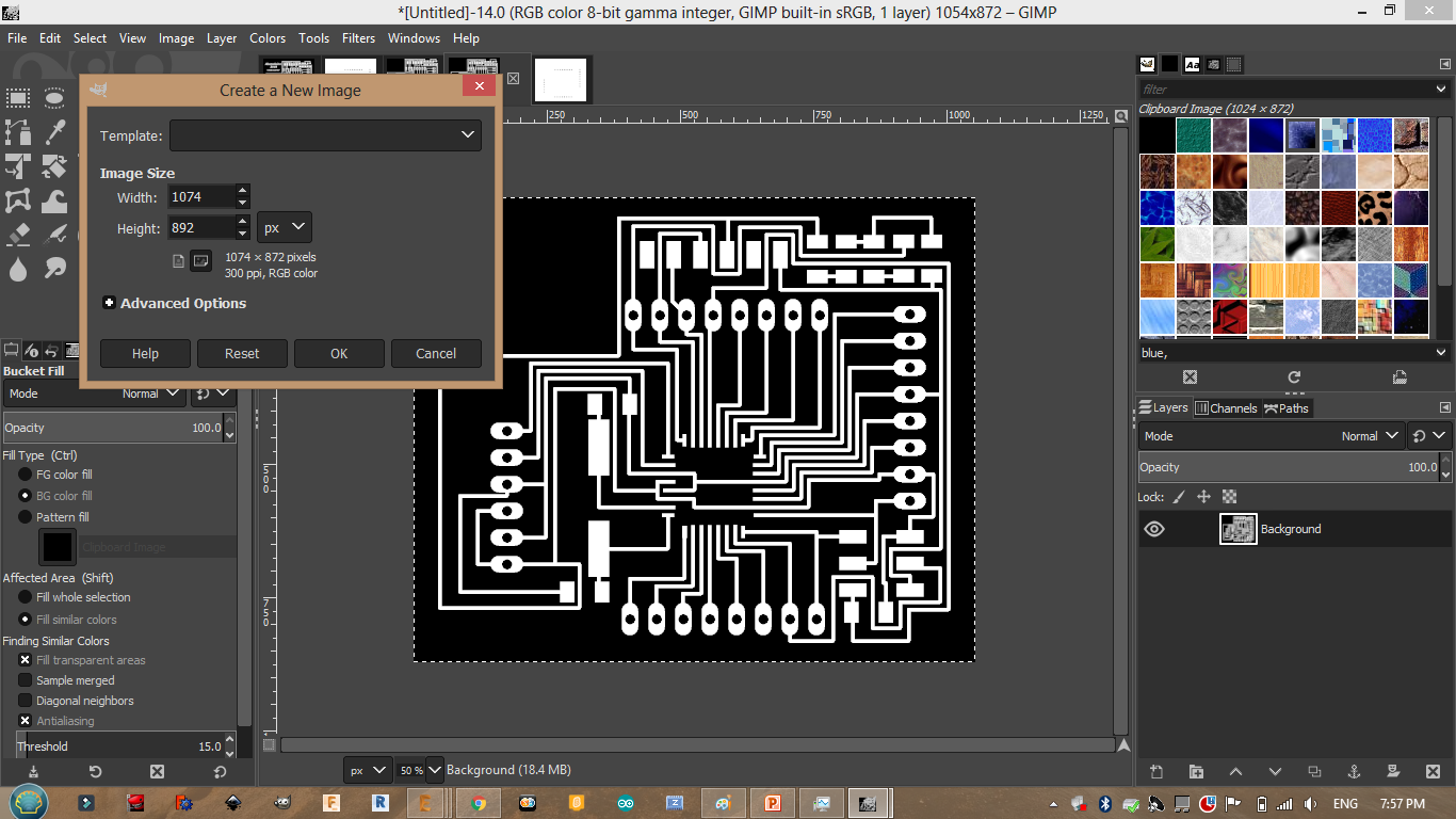
I painted the black sides with white.
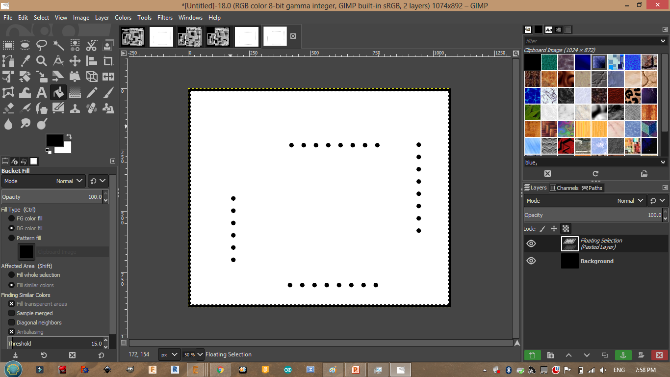


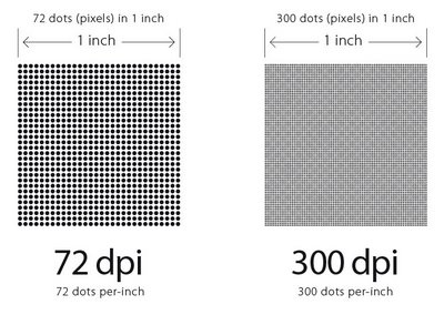
Note that the dpi is wrong.
milling
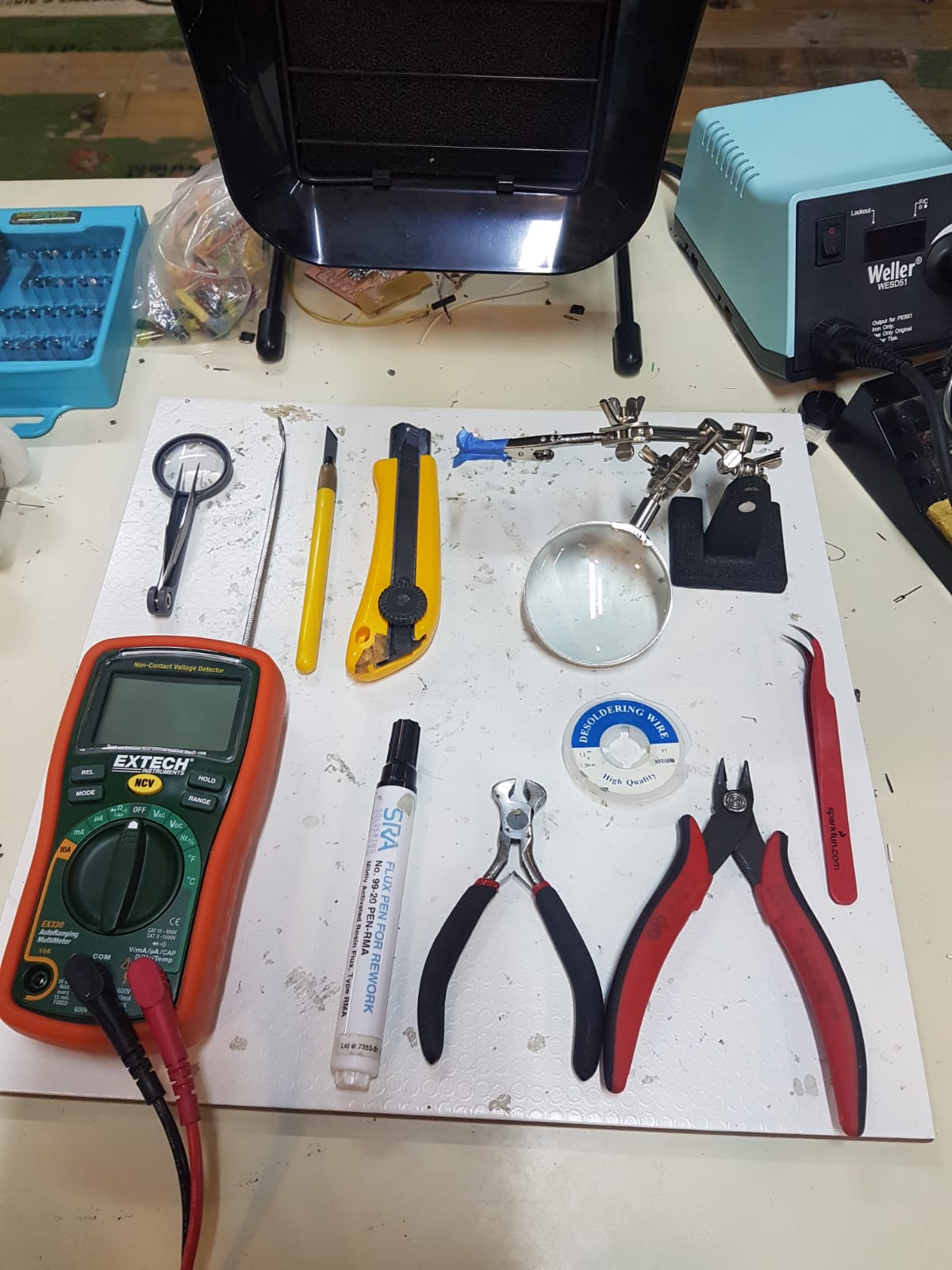
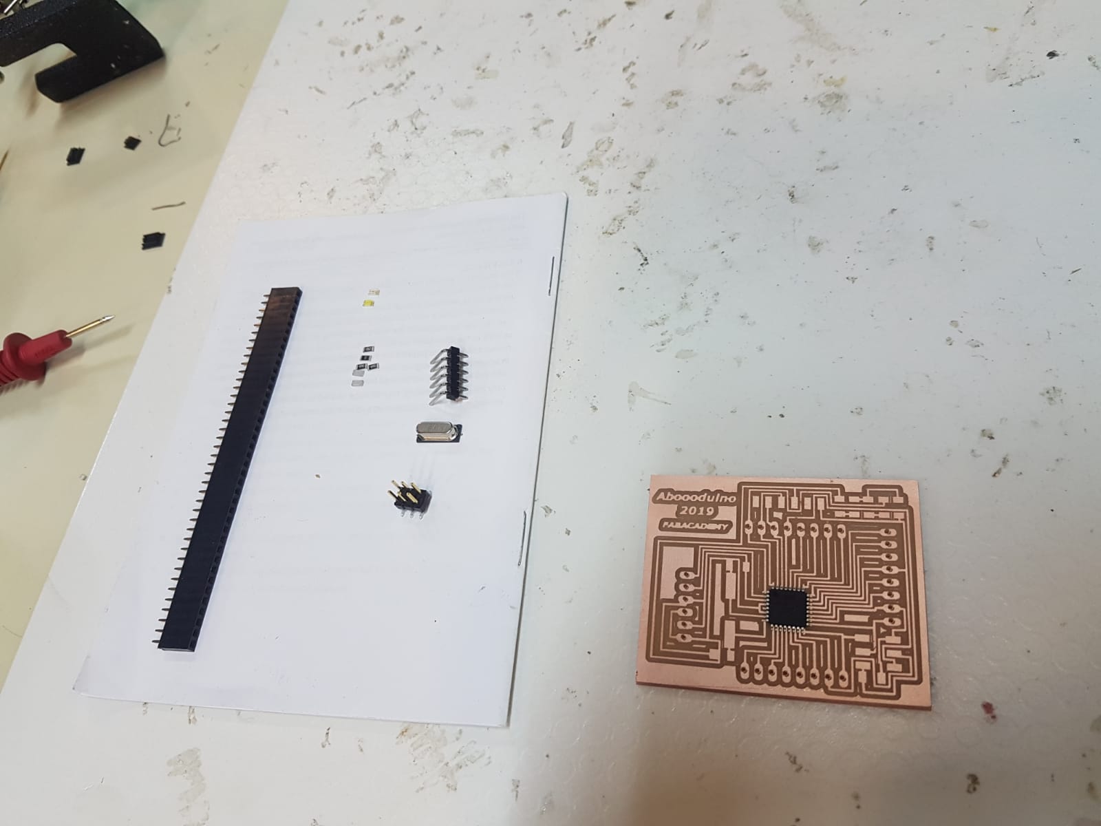
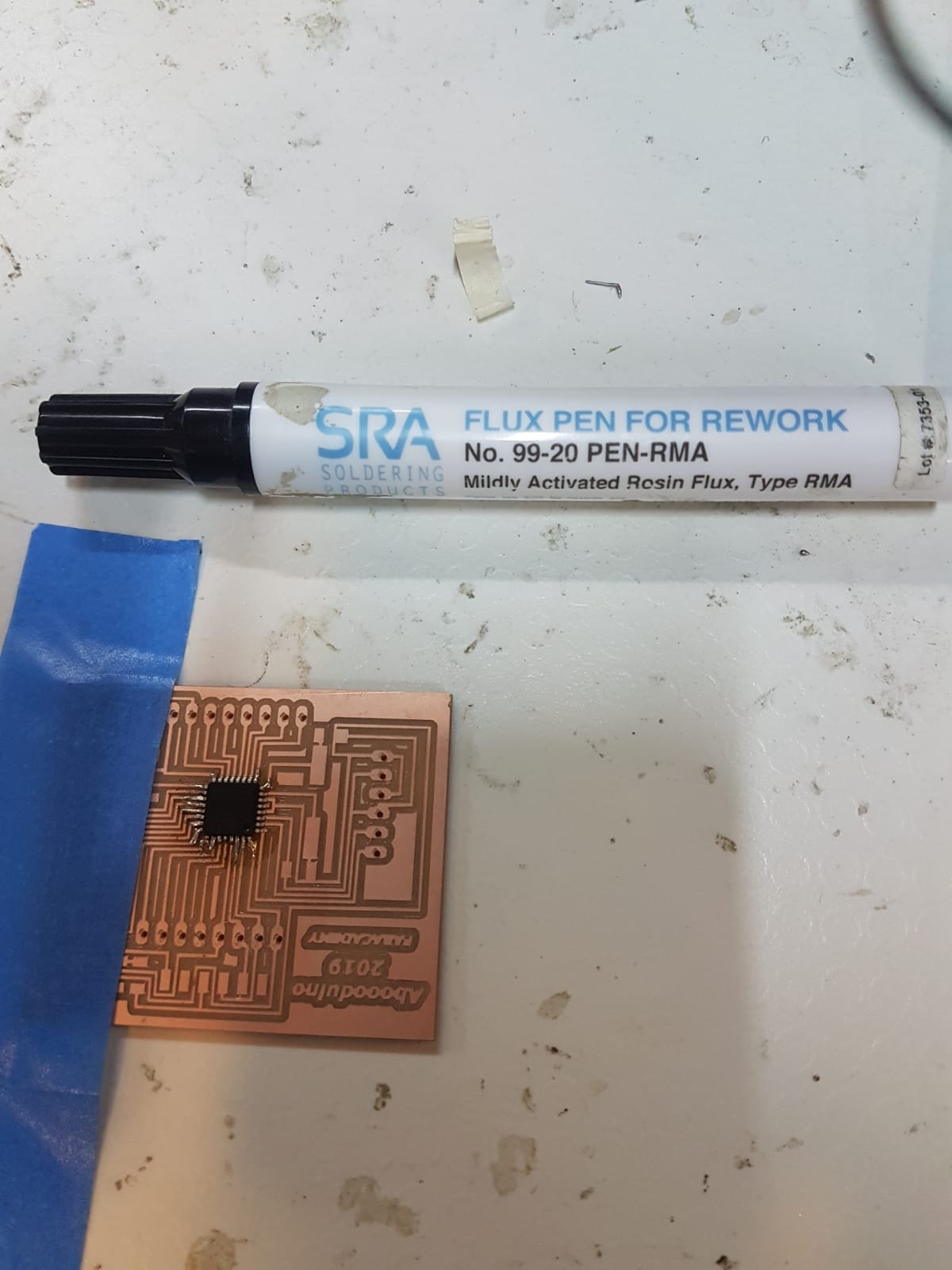
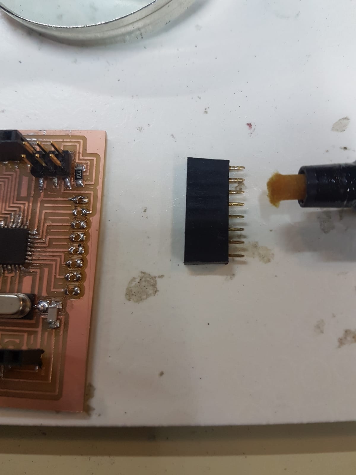
Useful tools note that the flux pen helped me alot in soldering
problem:
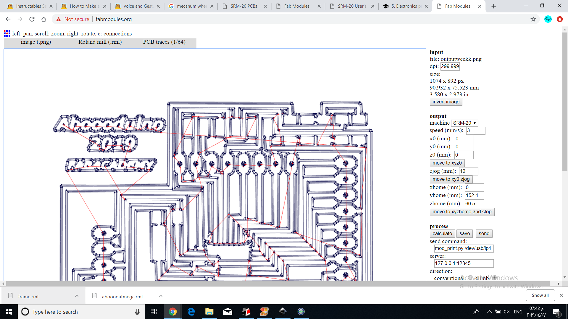
I have notised that the milling machine is milling a bigger size of my design
As you can see the dpi was wrong it should be the same that we have exported the board with which was 500 dpi.
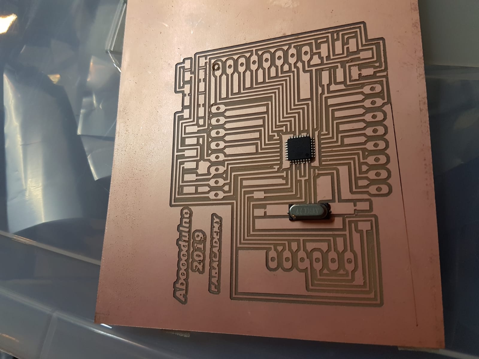
The components are smaller than the traces.
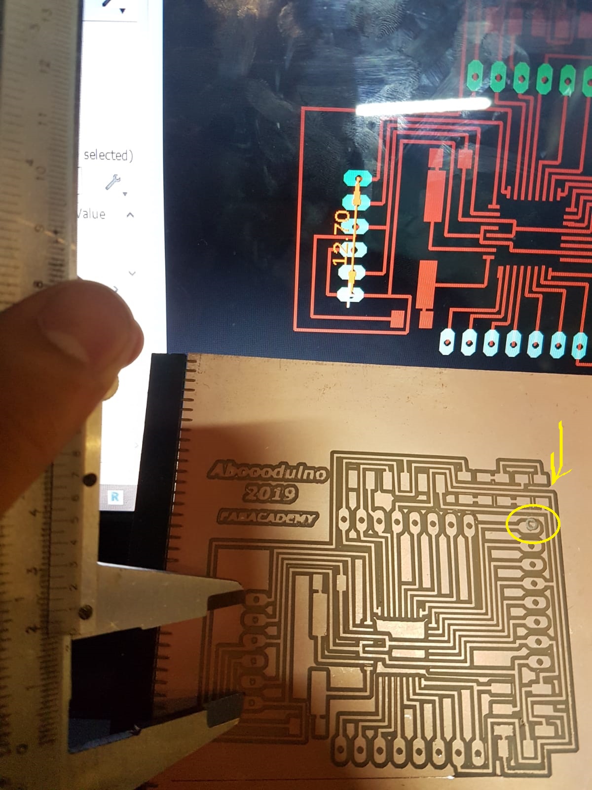
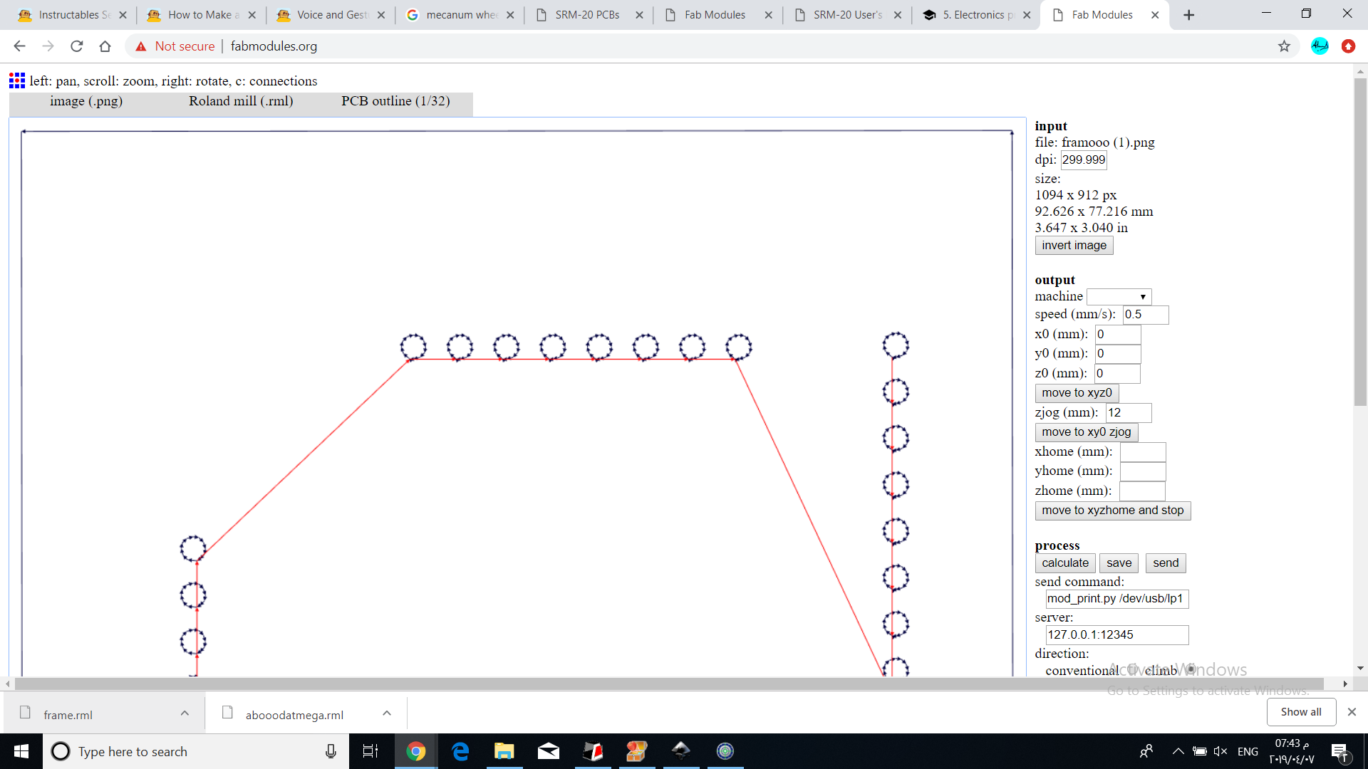
In addition to that the frame milling had a hole offset this was beacause the frame png and the circuit png didnt have the same exact size width*height. So the starting point will be defferent which will cause this offset.
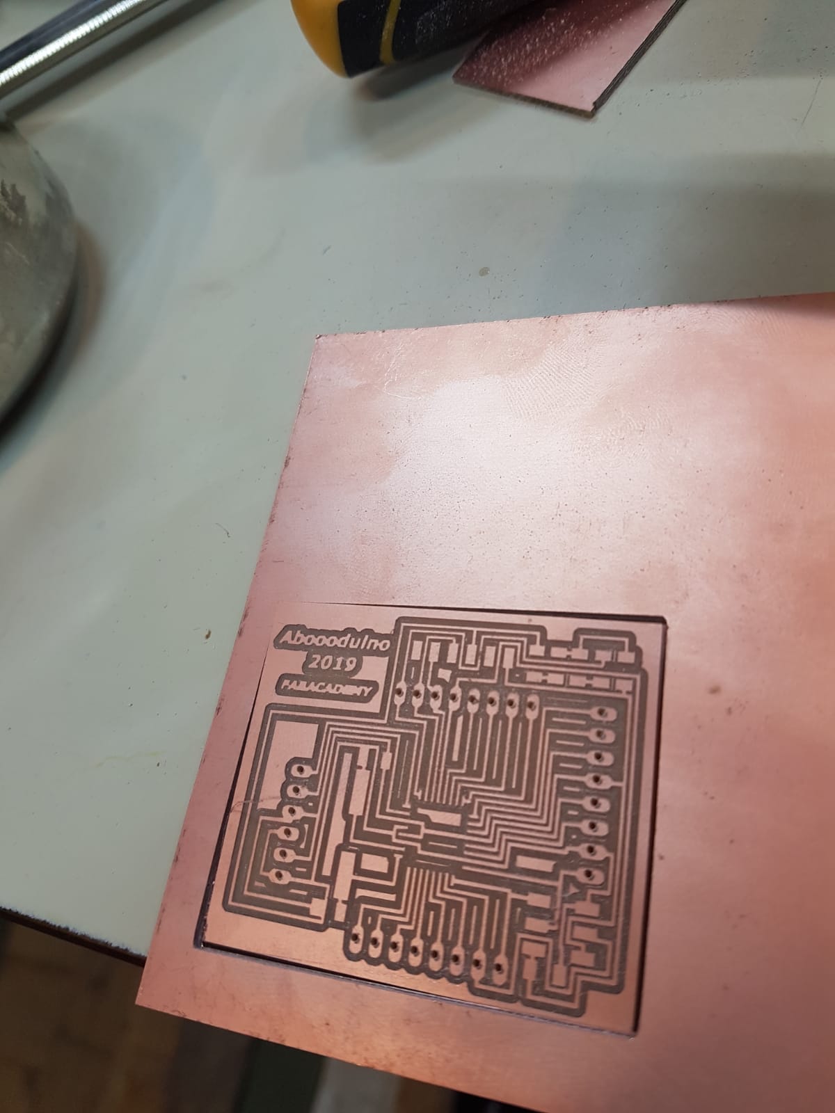
So I modified the fabmods dpi and the frame png so that the holes would be in the right place. Then remilled the pcb.
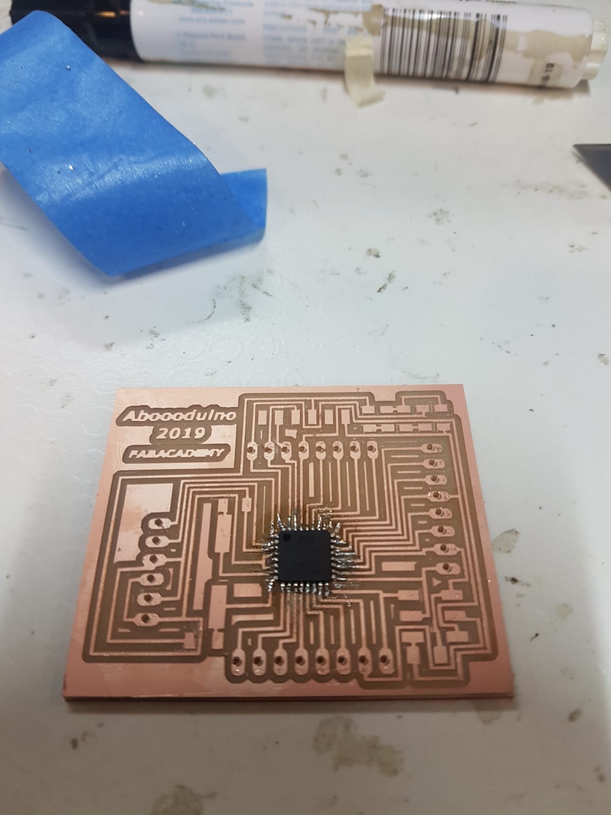
I placed atape to make sure the atmega doesnt move.
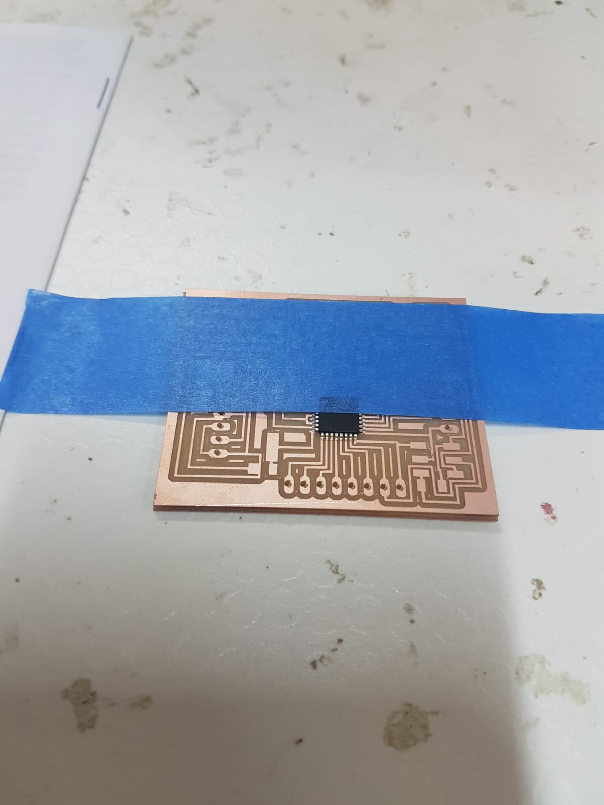
The flux pen helped me alot in soldering the atmega.
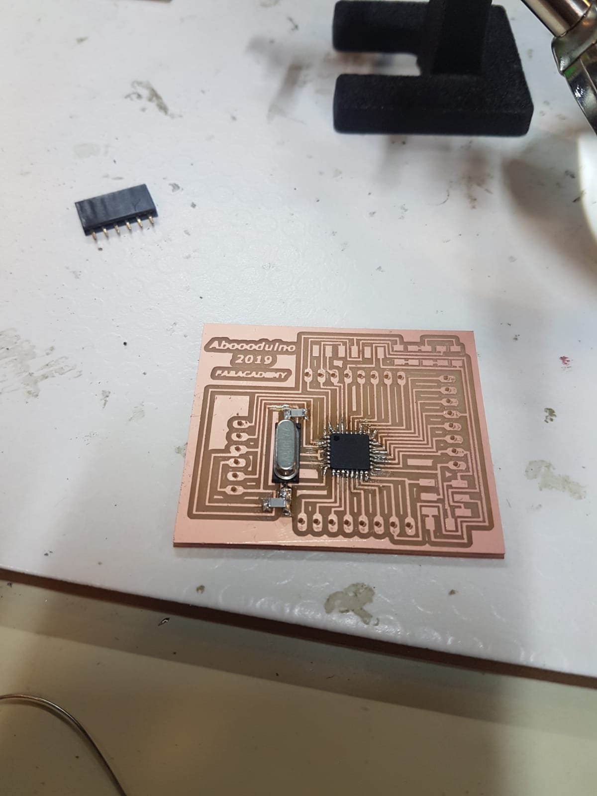
The flux pen helped me alot in soldering the female header.
Programming
I started with burn boot loader which will fix the timming.
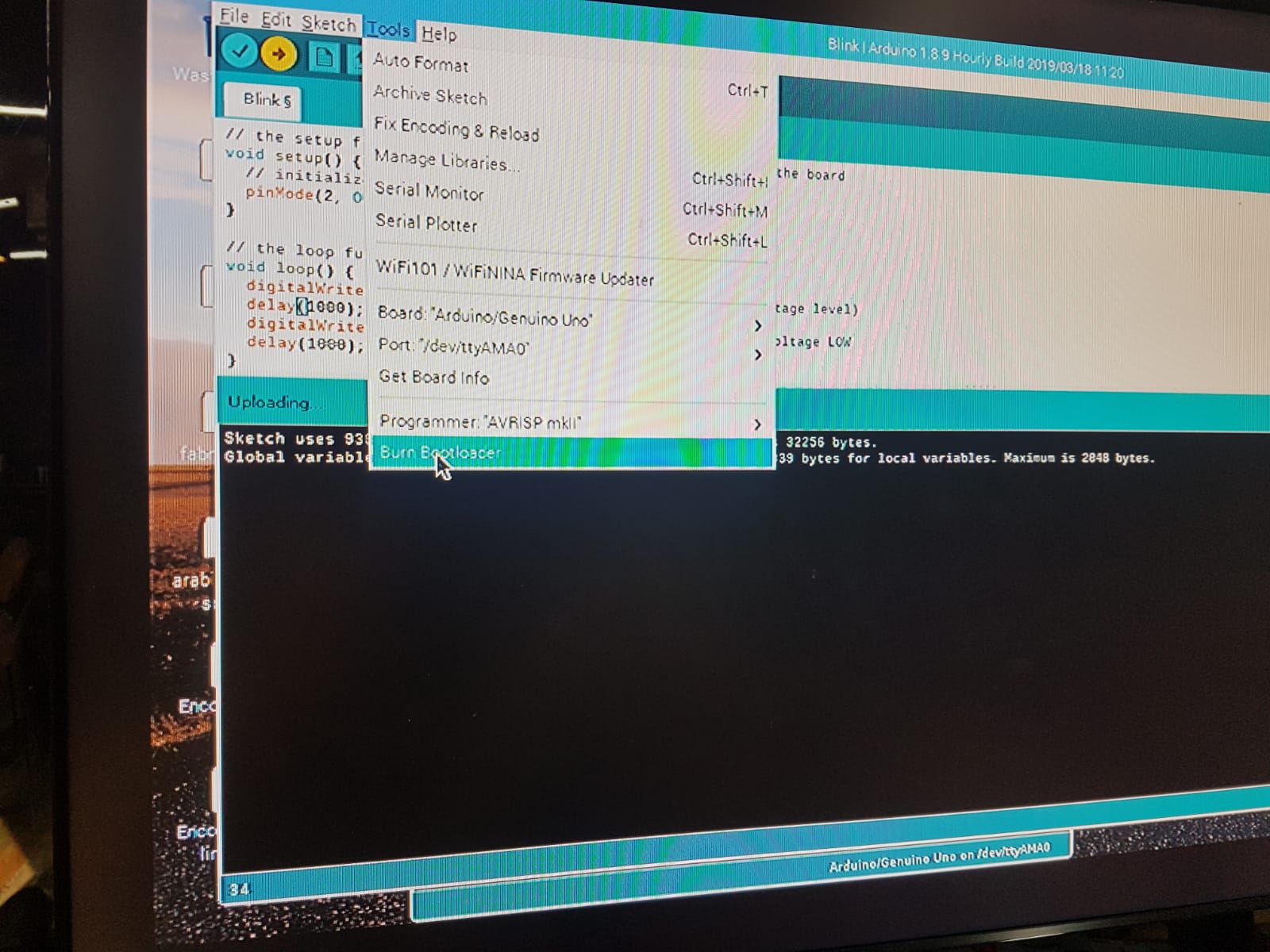
Then a simple blink test.
Then I tryed a stepper motor.

Code:
Blink
void setup() {

  pinMode(2, OUTPUT); //My bord LED is connected to pin 2
}


void loop() {
  digitalWrite(2, HIGH);   // turn the LED on (HIGH is the voltage level)
  delay(1000);                       // wait for a second
  digitalWrite(2, LOW);    // turn the LED off by making the voltage LOW
  delay(1000);                       // wait for a second
}
Stepper motor
#include <Stepper.h>
#define STEPS 2038 // the number of steps in one revolution of your motor (28BYJ-48)
Stepper stepper(STEPS, 8, 10, 9, 11); //set the stepper pins
void setup() {
  // nothing to do
}
void loop() {
  stepper.setSpeed(10);//  rpm
  stepper.step(2038); // do 2038 steps -- corresponds to one revolution in one minute
  delay(1000); // wait for one second

}