11. Input devices
Our goal in this week is to design a circuit that would host input devices like sensors. It will have the same components that the arduino has. In my case I will add accelerometer and ultrasonic sensor as inputs to serve my final project.
Group Assignment
Testing sensors
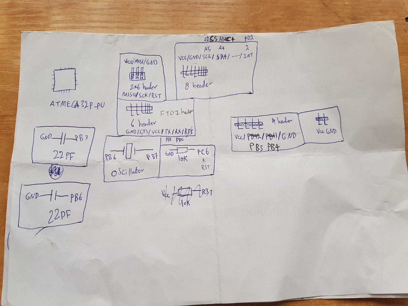
Understanding the connections and components needed:
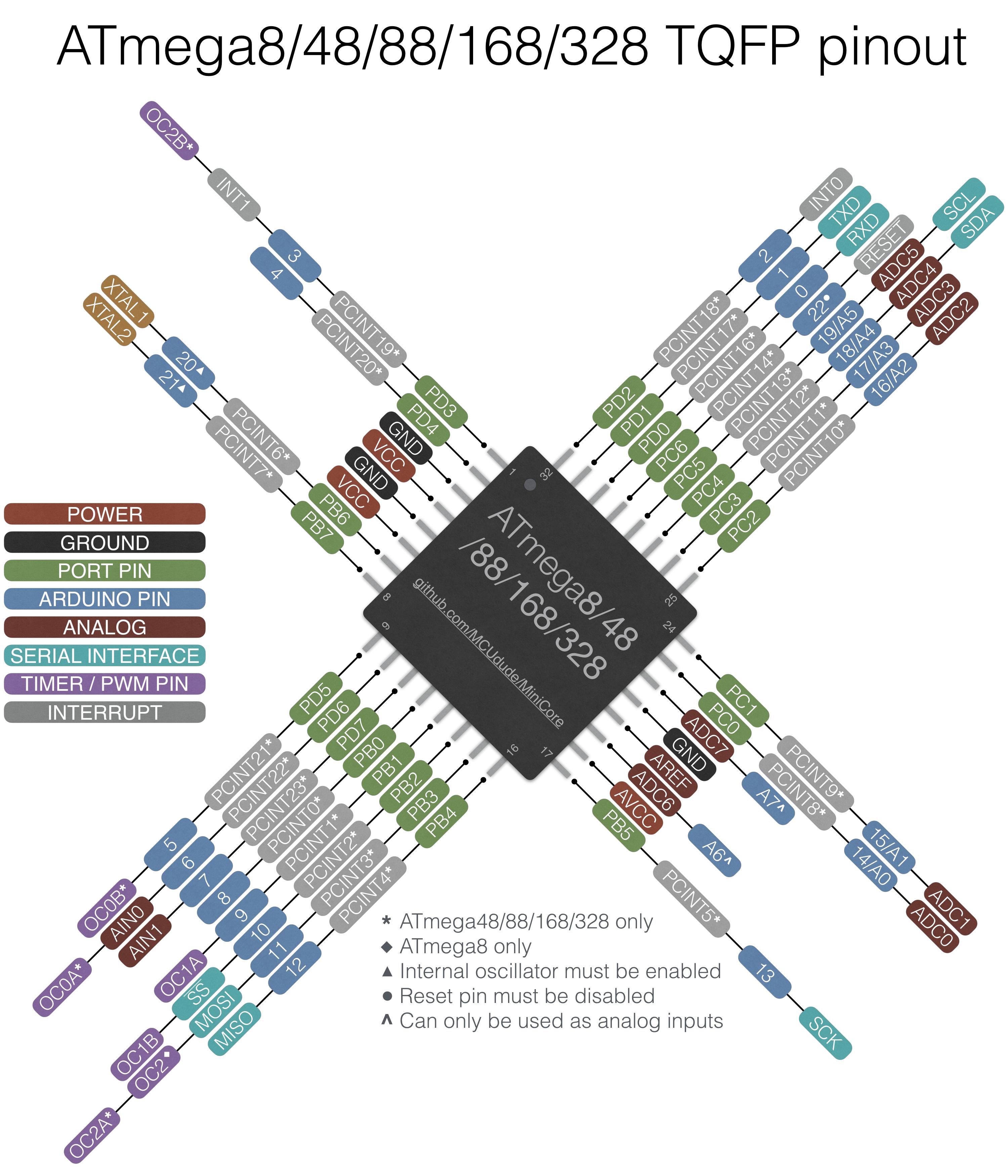
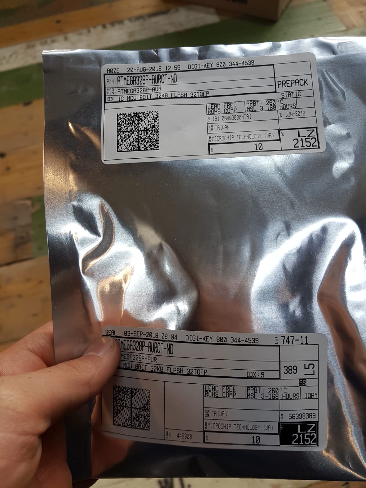
In the begging I had to look for the datasheet of the microcontroller Atmega328p and the other sensors so we can understand the ports.
Datasheet:
Note : atmega328p-aur = atmega328p-pu “aur” is the surface mount and “pu” is through hole type. : smd means surface mount.
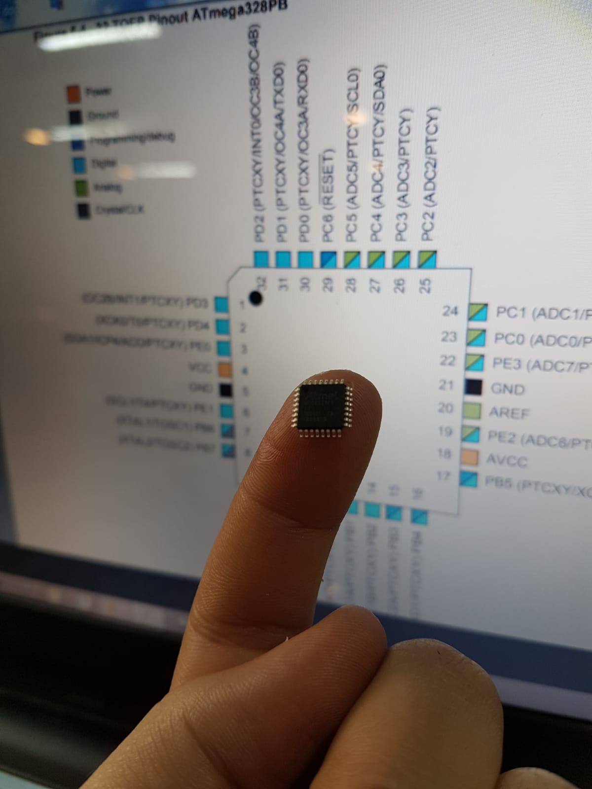
Then I googled arduino schematic atmega328p-pu to find the minimum components needed to operate the atmega
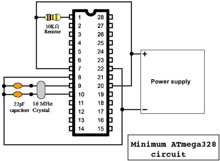
I googled arduino schematic atmega328p-pu ports to be able to match the wires or click the link or you can view the atmega datasheet328p.
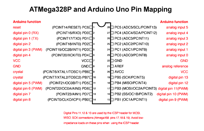
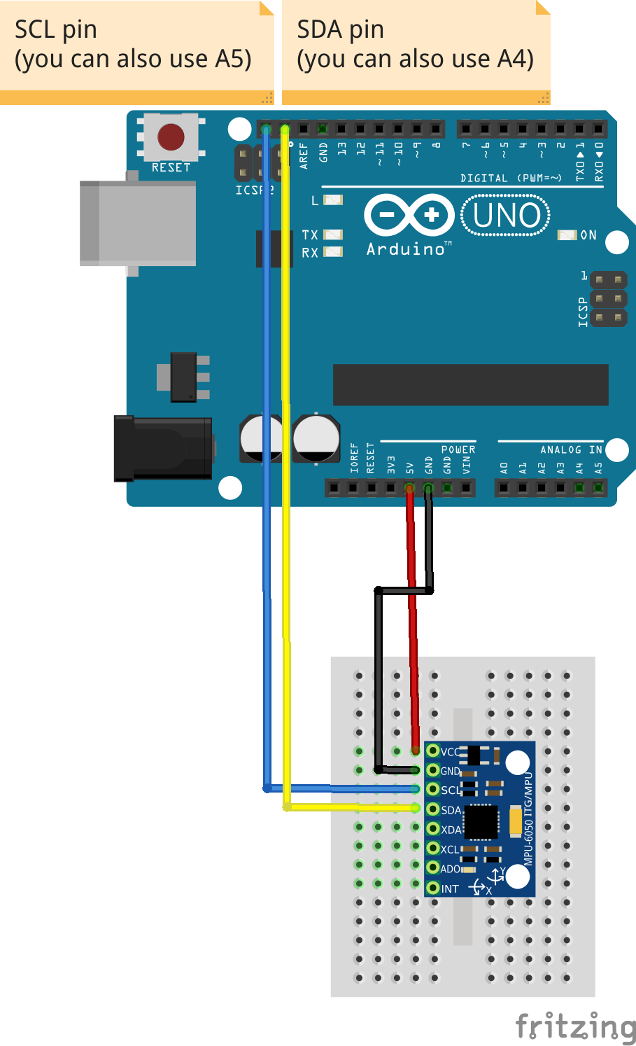
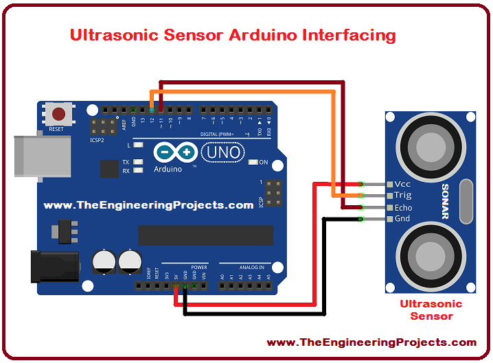
After that I had to see how the sensors are connected in the arduino so I can match the connections.
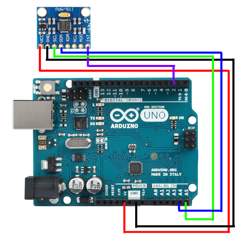
I could have also used this configuration.
Components:
| Qty | part name | Total Price “$” ‘BHD’ | Description |
|---|---|---|---|
| 1 | ATmega328p-aur | “2” ‘0.75’ | Microcontroller |
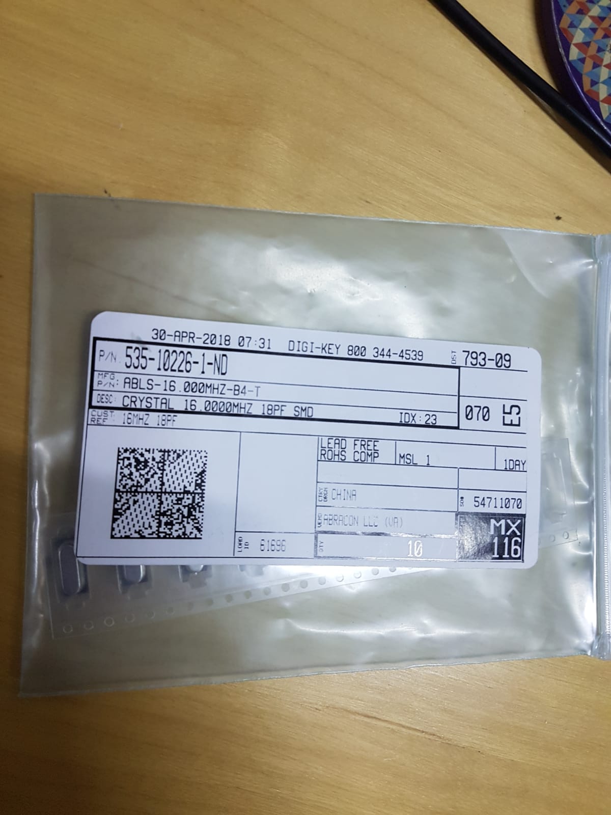
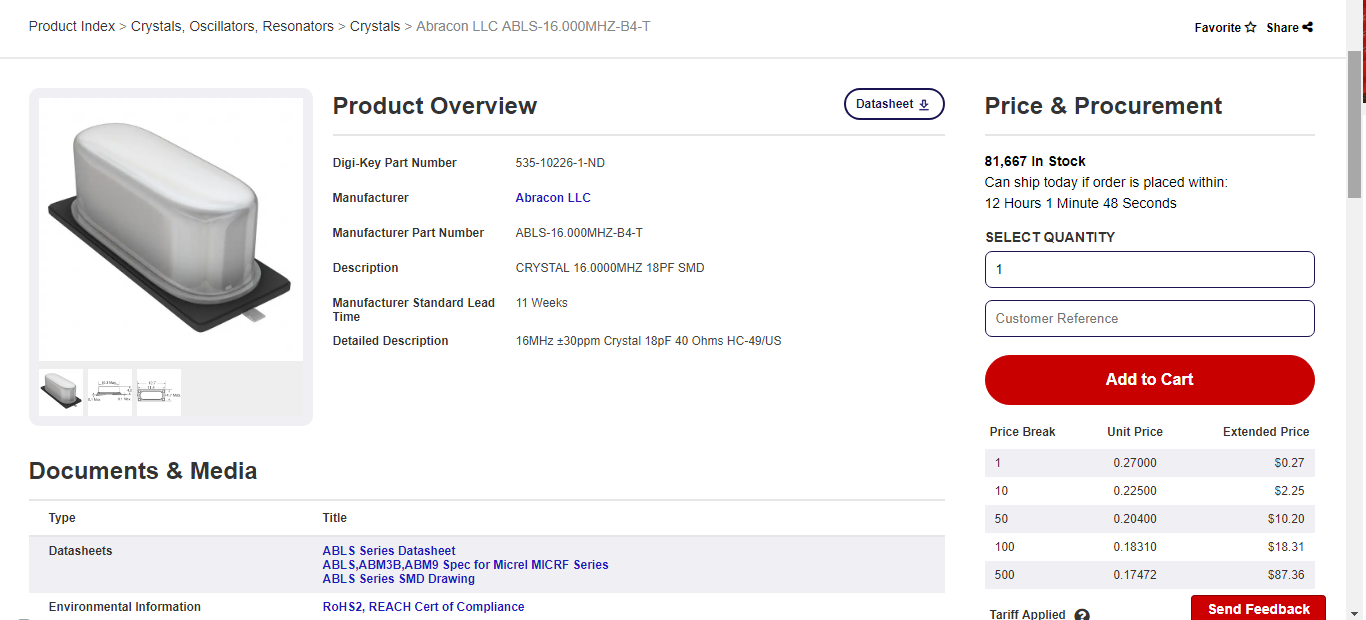
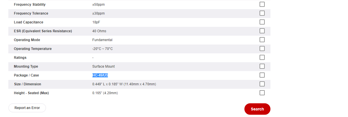
| 1 | Crystal 16mhz | “0.3” ‘0.1’ | Timer |
| 2 | Capacitor | “0.2” ‘0.075’ | 18pF smd for the Crystal googled “Crystal 16mhz recomended capacitors” |
| 1 | Resistor | “1” ‘0.38’ per 20pcs | 10k ohm for the RST “reset port” |
| 2 | LED | “2” ‘0.75 per 25pcs | Indicator |
| 2 | Resistor | “1.2” ‘0.45’ | 500 ohm for the LEDs |
| 1 | Resistor | “2” ‘0.75’ | 0 ohm jumper |
| 1 | 2x3 Pin Header | “1.5” ‘0.54’ per 10pcs | AVR ISP SMD |
| 1 | 1x6 Pin Header | “1.5” ‘0.54’ per 10pcs | Programming pins “FTDI-SMD-HEADERS” |
| 1 | 1x8 Pin Header | “1.5” ‘0.54’ per 10pcs | Accelerometer board male pins |
| 1 | 1x2 Pin Header | “1.5” ‘0.54’ per 10pcs | Ultrasonic pins |
| 1 | 2x2 Pin Header | “1.5” ‘0.54’ per 10pcs | Ultrasonic power and circuit power |
| 1 | PCB Circuit Board | “1.4” ‘0.53’ | |
| External parts | |||
| 1 | 1x8 Pin Header | “1.5” ‘0.54’ per 10pcs | Accelerometer board female pins |
| 1 | gy-521 | “1.5” ‘0.54’ | Accelerometer board |
| 1 | Ultrasonic sensor | “1” ‘0.38’ | Ultrasonic board |
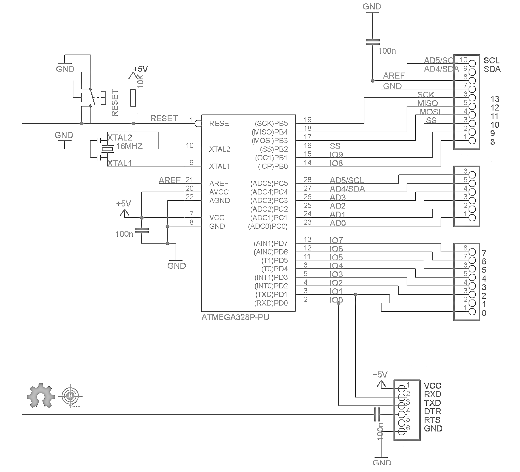
Designing:
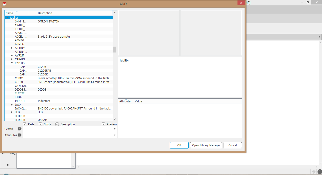
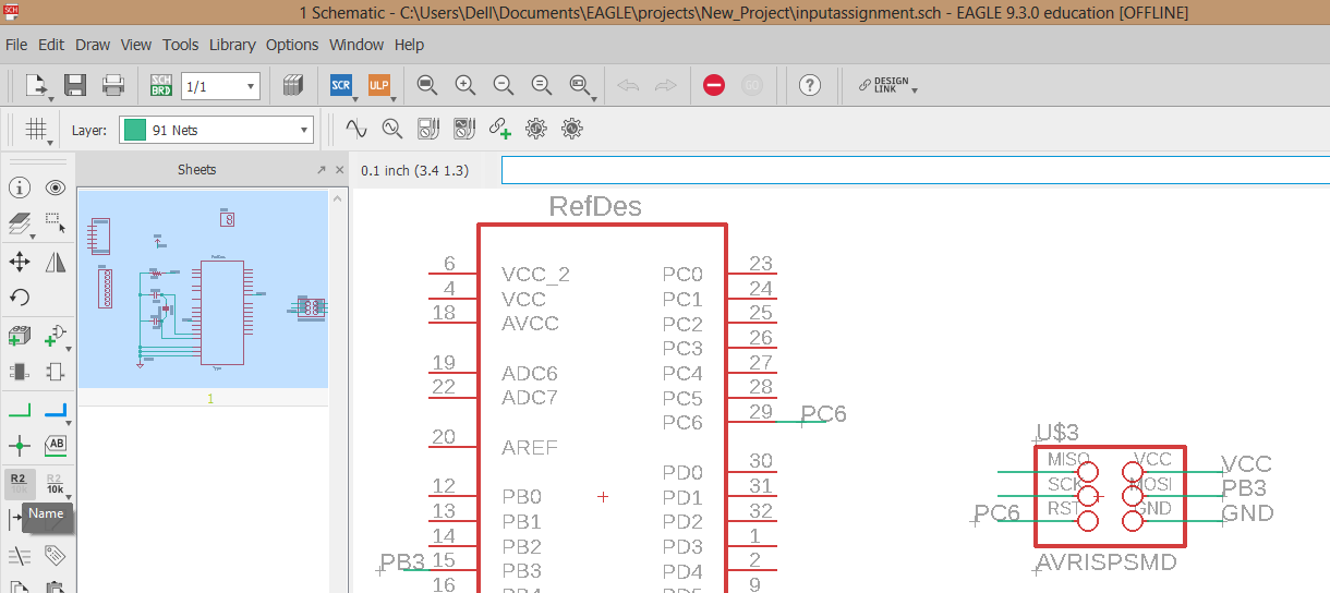
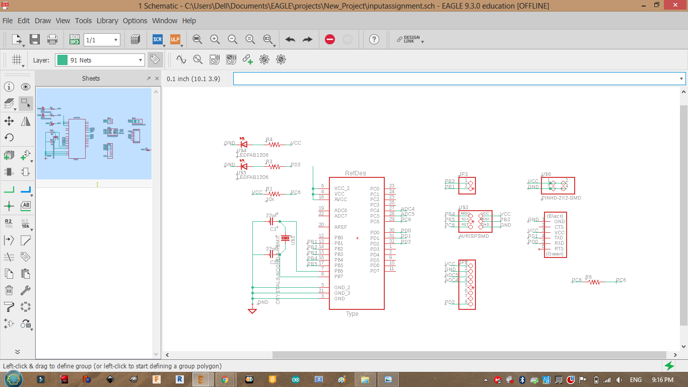
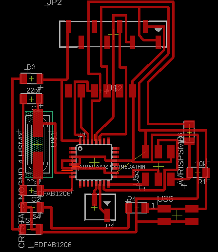
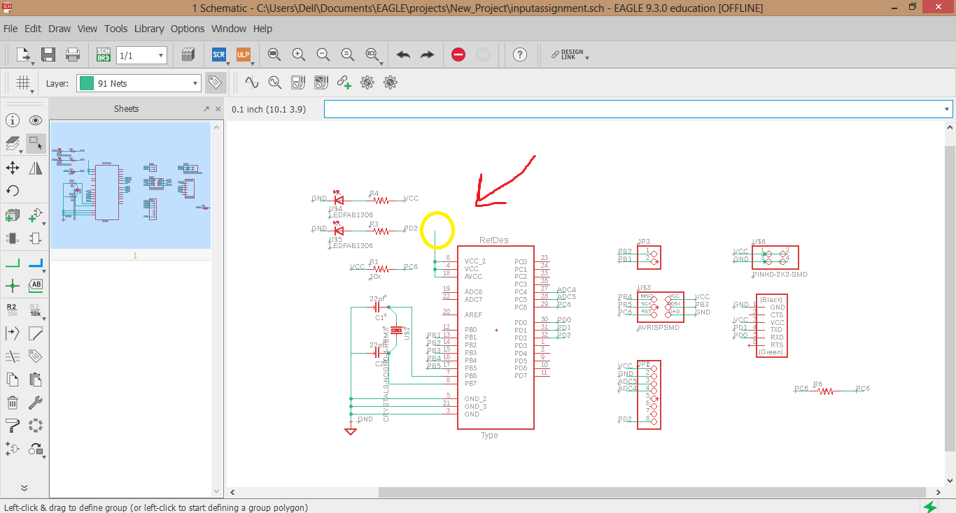
After understanging the connections and the components needed we can start addind the parts to our schematic and wire them. The connections for the sensors will be as a male connection so we can later wire the sensors externally.
A clean way to wire your component is to add a small wire then label or name it withe its end distination.
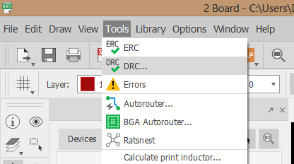
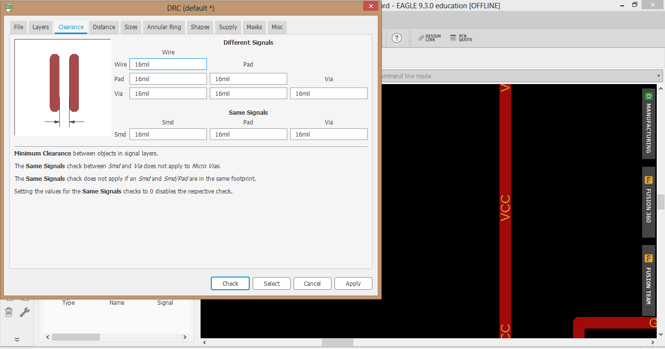
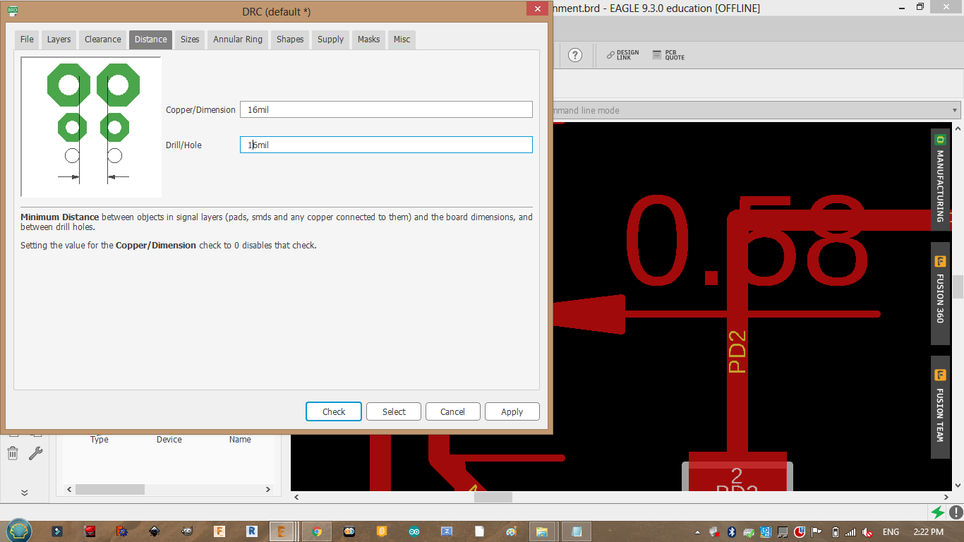
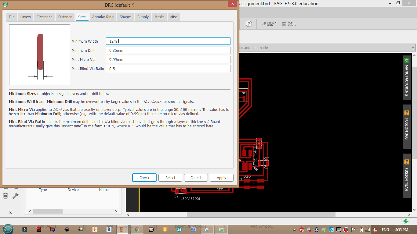
Switch from SCH to BRD ,before arranging the wires we have to set some rules to protect our design from exeeding its limits of milling. Click on Tools >> DRC
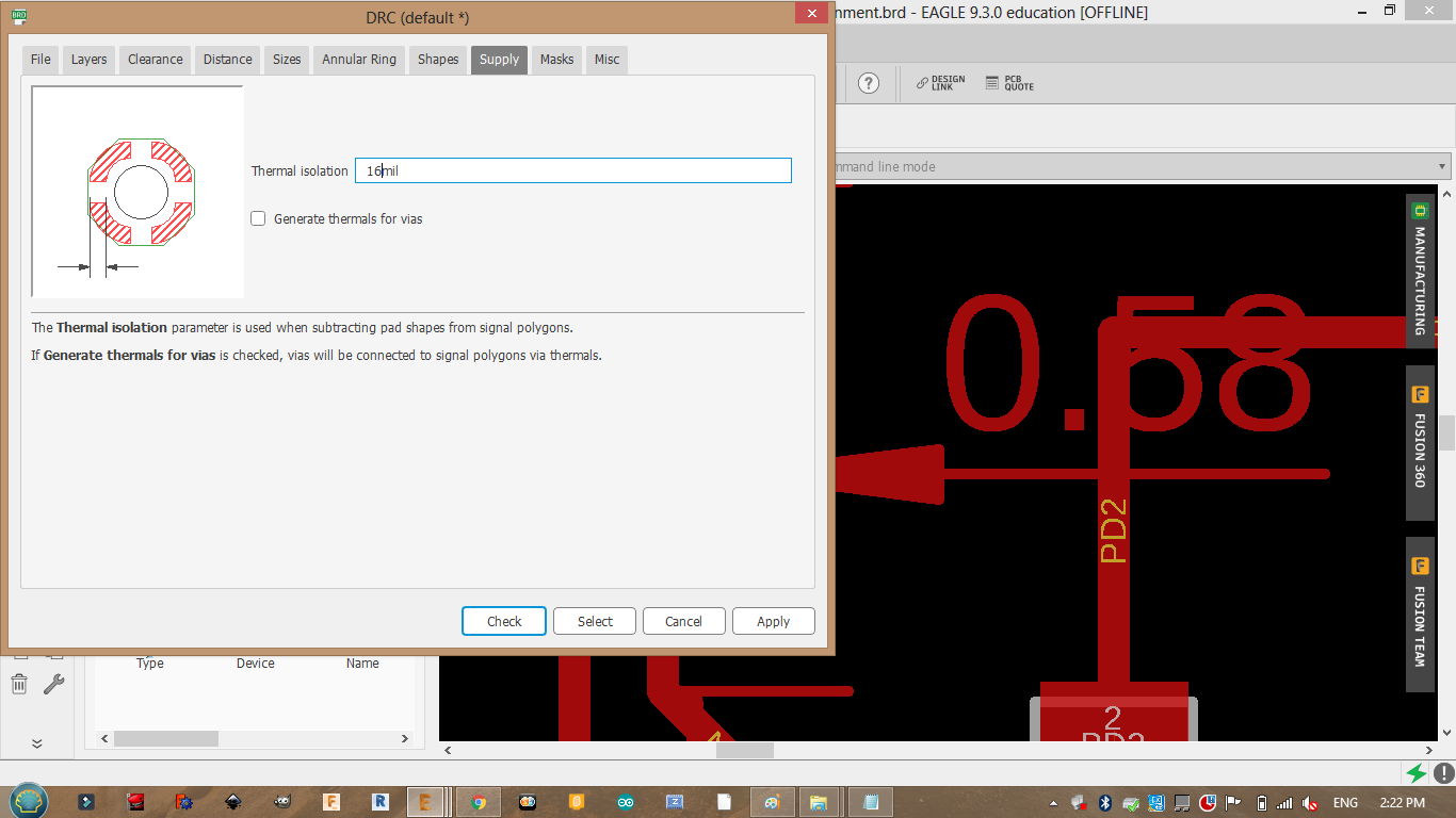
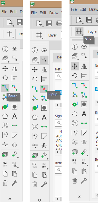
You will see yellow lines to gide your wiring you can wire by clicking on the symbol shown below a small tip reduce the grid size to make you feel more comfortable when wiring.
This picture shows a small problem when I set my rules They didnt save so the wire thickness was less than what needed this allowed me to wire in small spaces “exeded the limits”. I started wiring again and made sure that the design rules are saved.
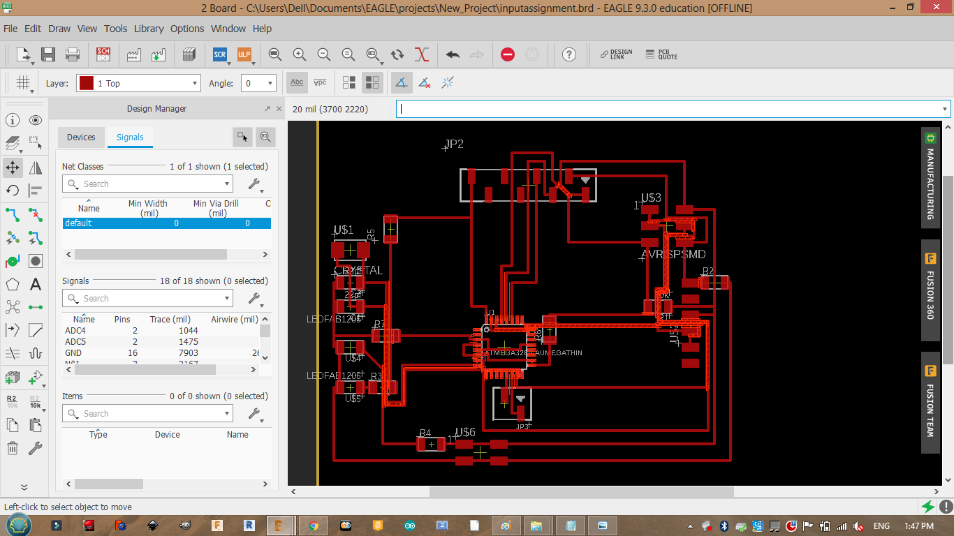
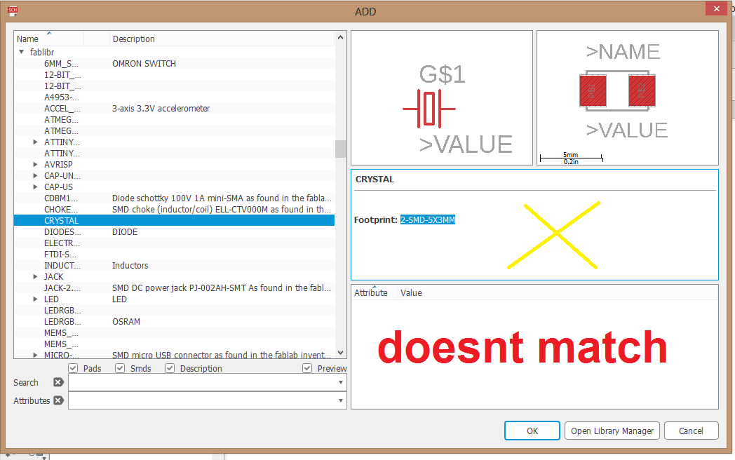
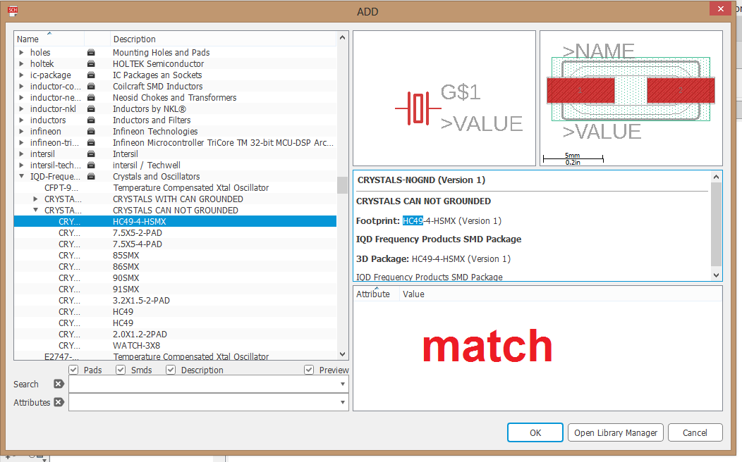
In addtion to this problem I added the Crystal which I saw in the fab library without making sure that the foot print matches the one that we have. Next time I will search the part in digikey then make sure that the written footprint matches the added one.
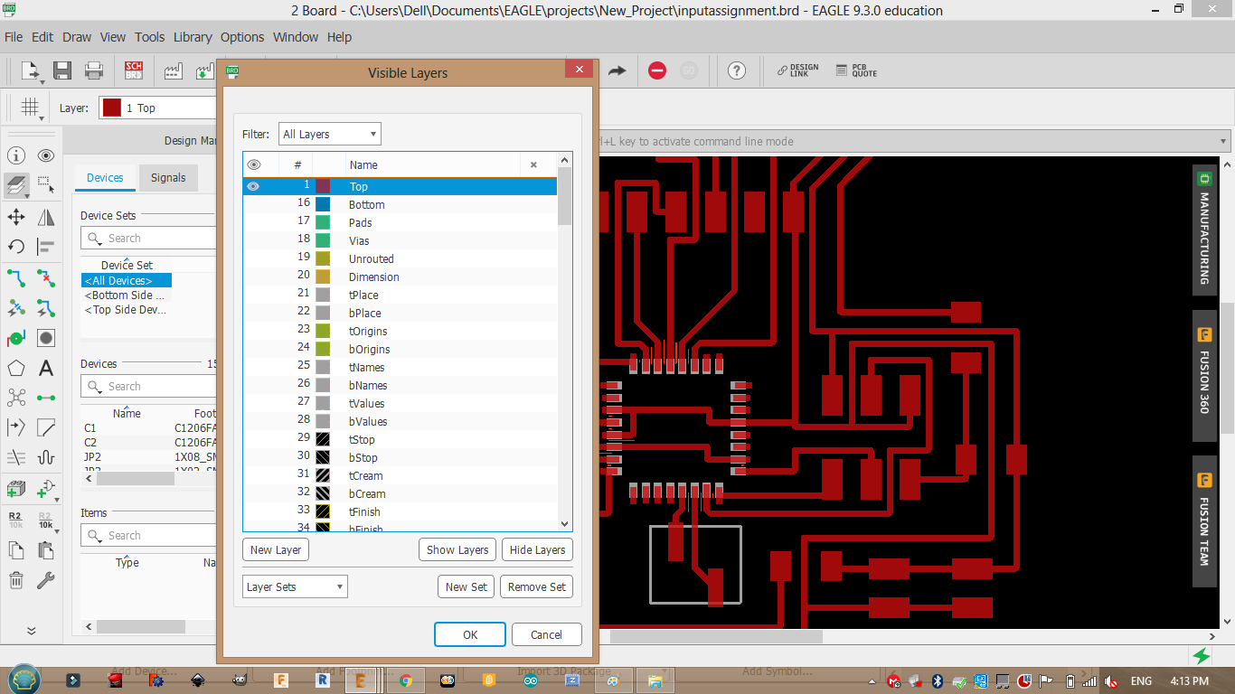
We need the top layer only so I will hide the rest layers.
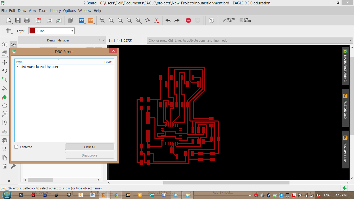
I also checked my design rules DRC >> check I had some errors but they were negligible so I cleared all errors.
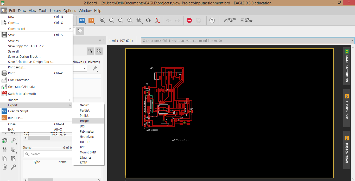
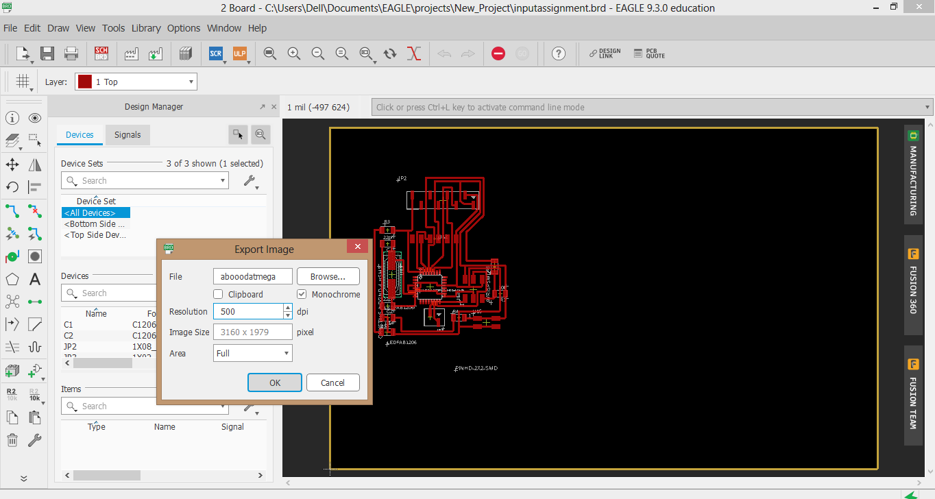
Export as image and add frame:
Usefull site instructions
I had to export the file as an image.
Gimp
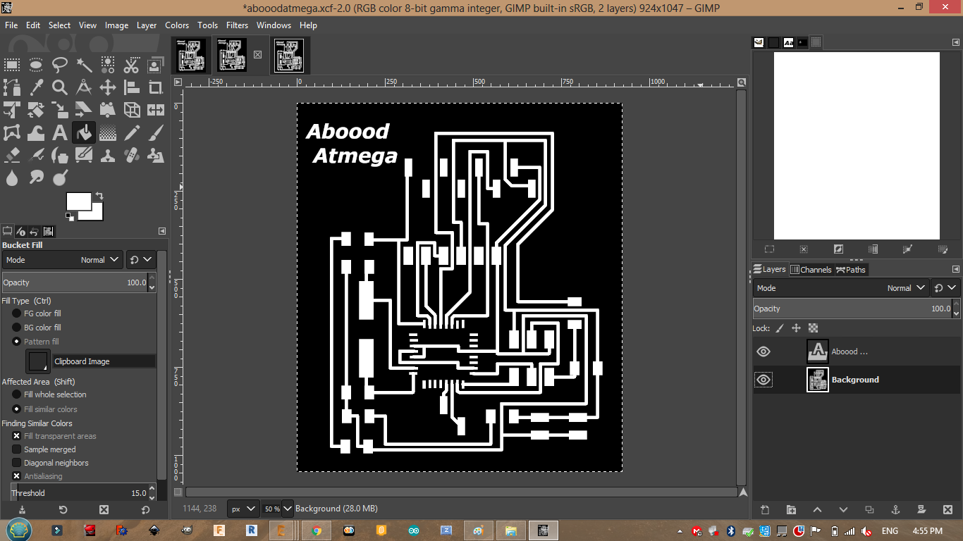
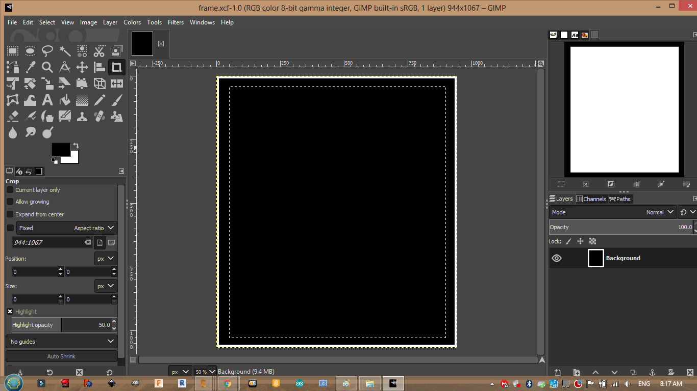
After exporting the design as black and white image I added my oun touch to it using gimp and made a frame.
First sat the fit size.
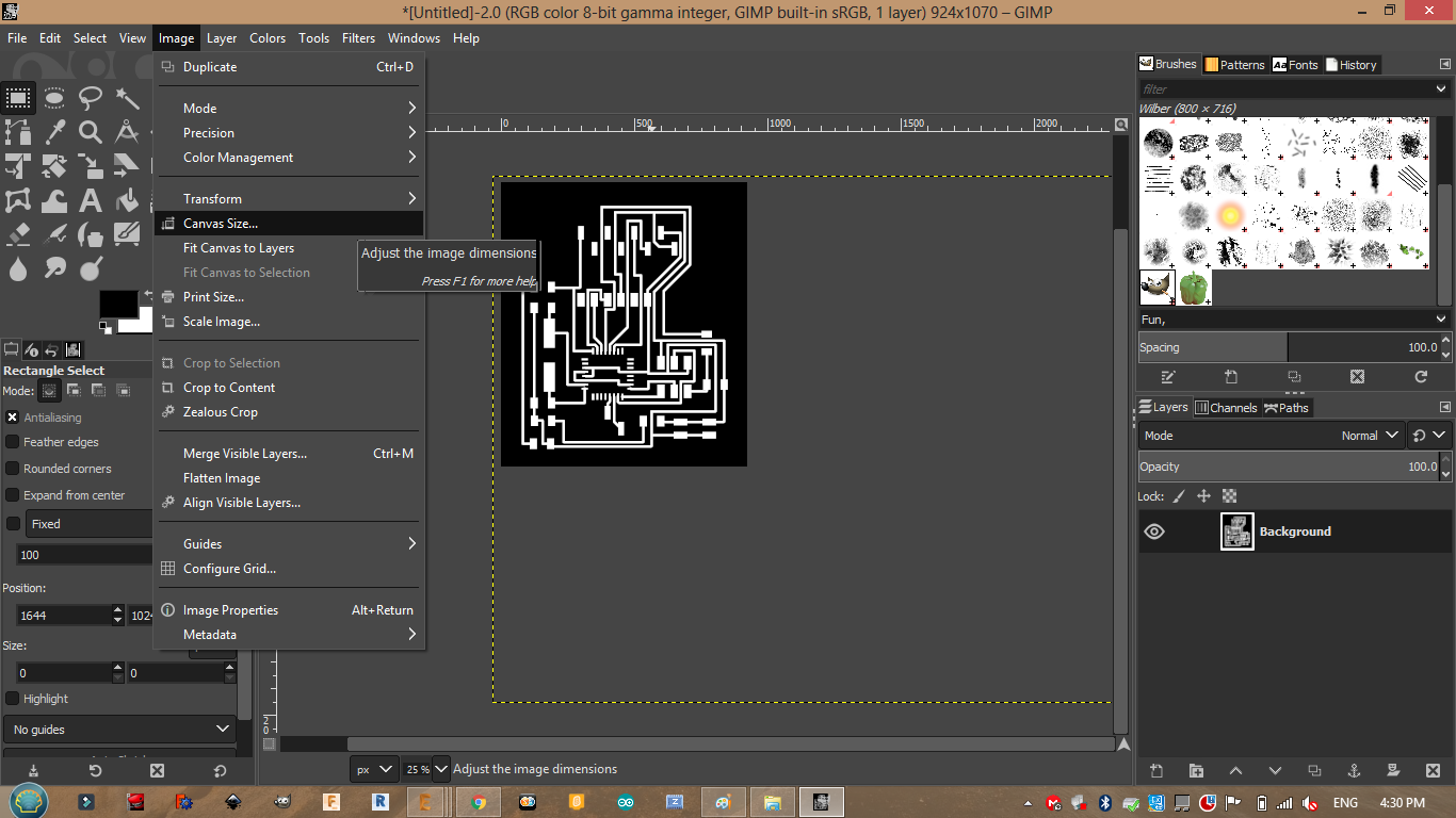
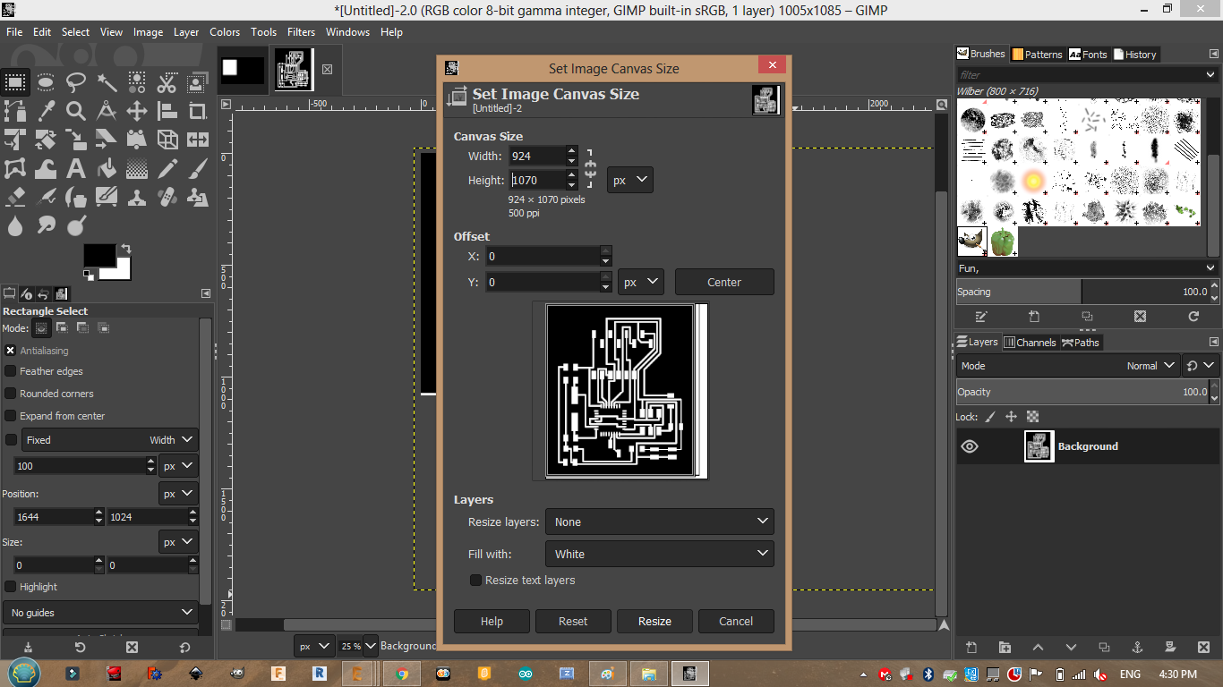
Then open new project and copy the image to it ,add 20 px more for each side.
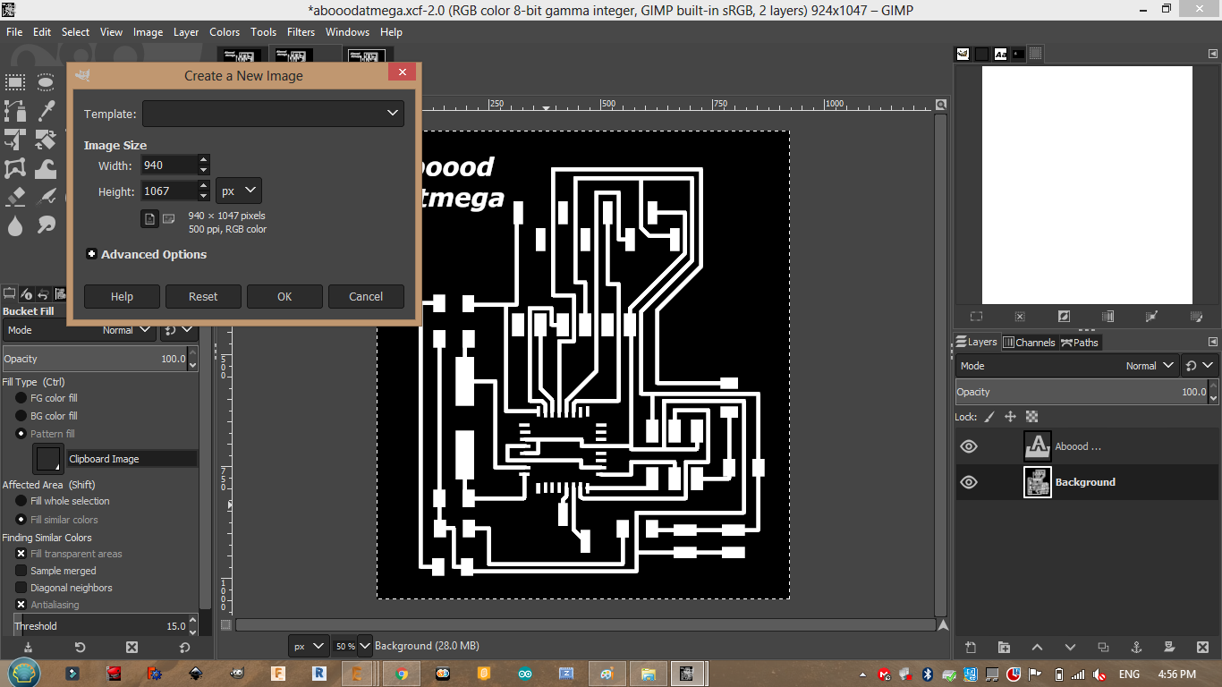
Then color the white traces with black or stick a square to the traces to hide them and save the file.
Milling:
Using the same steps mentioned in week5 I milled my PCB.
First upload the png file to fabmodules.
.png)
.png)
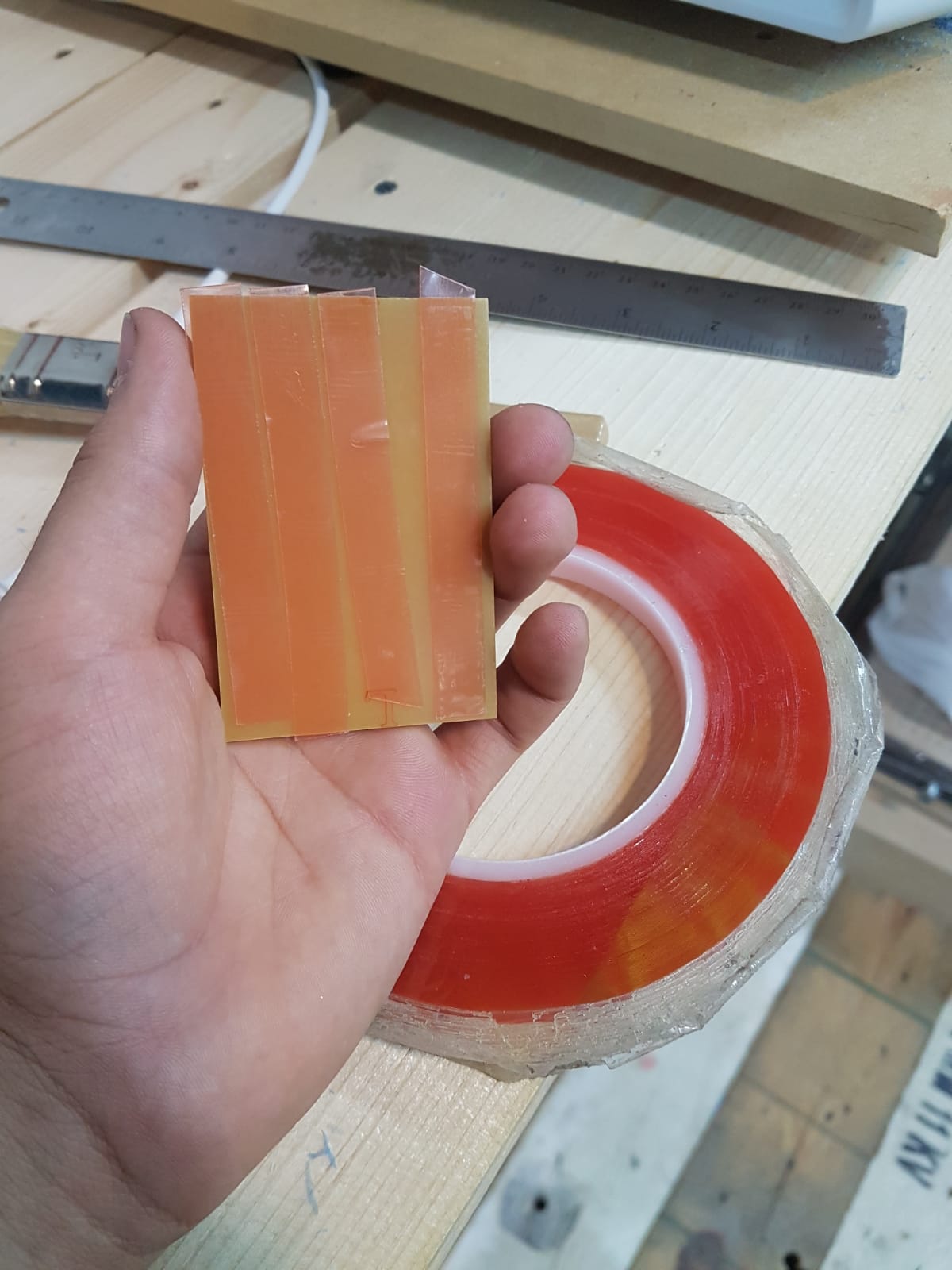
I added double sided tape to the bottom of the PCB.
After that I sat my origins and speed.
.png)
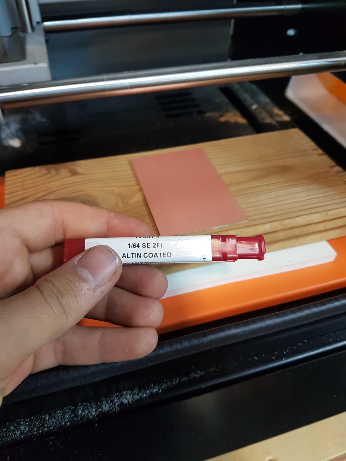
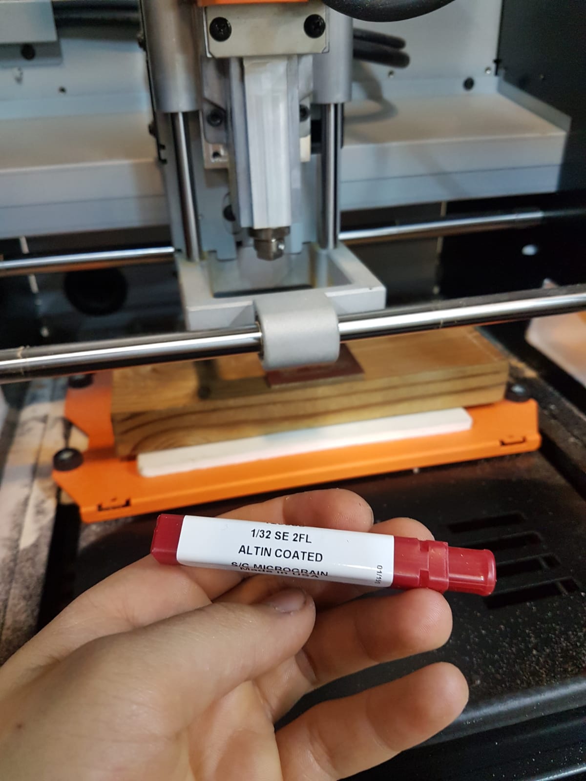
Then I started with tracing the lines using 1/64 bit.
After that I made the cut through for the frame using 1/32 bit.
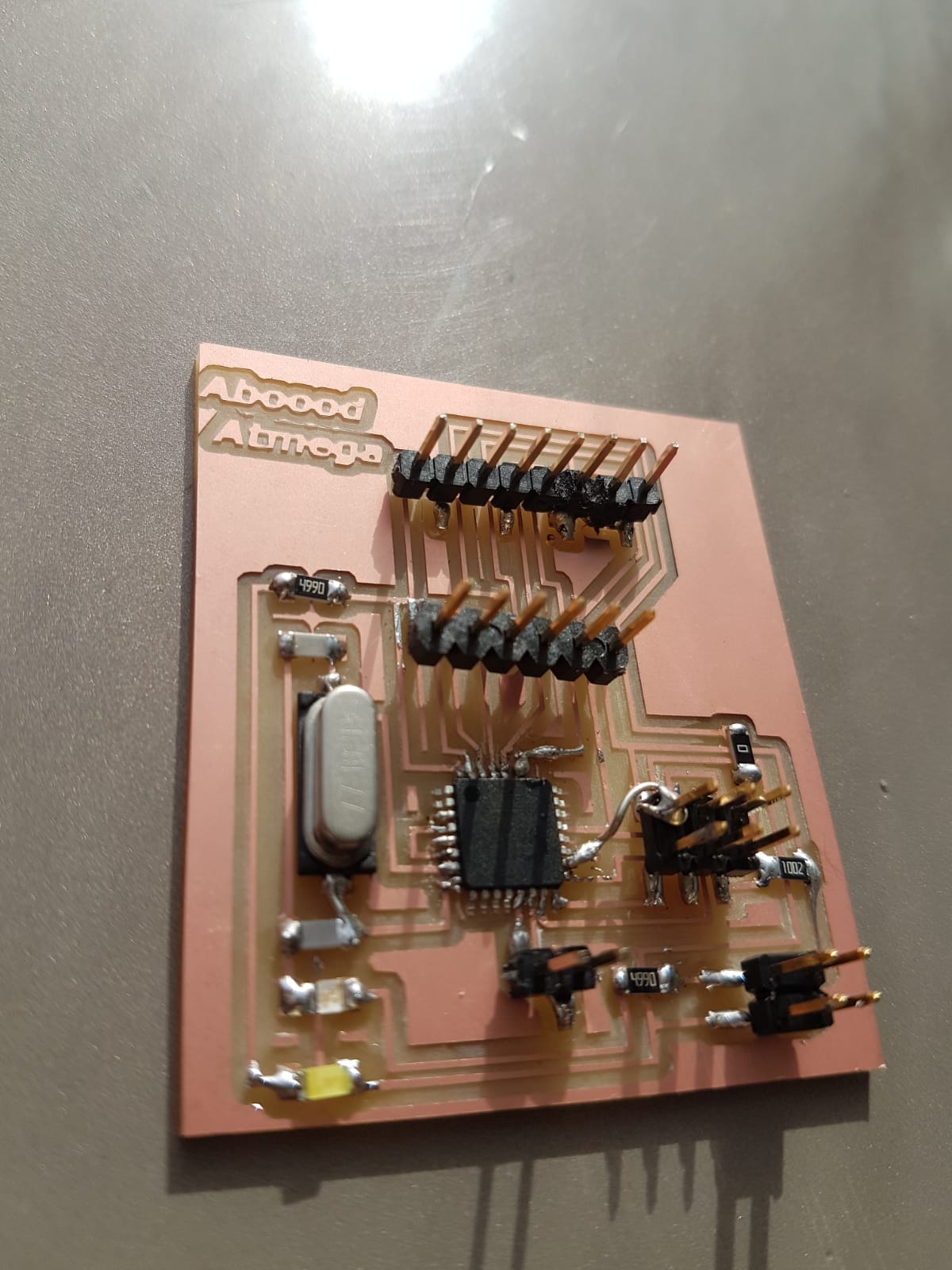
Soldering:
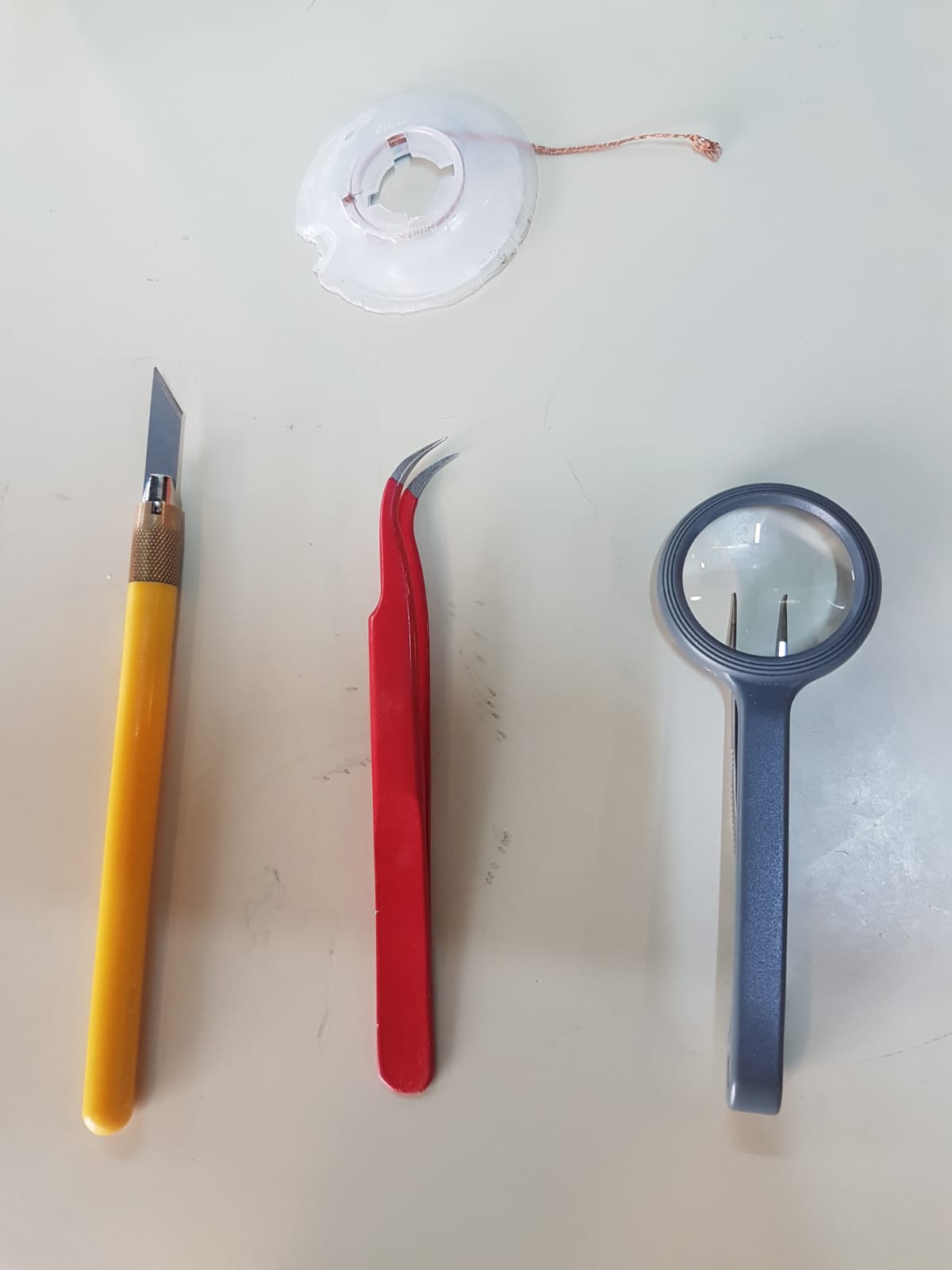
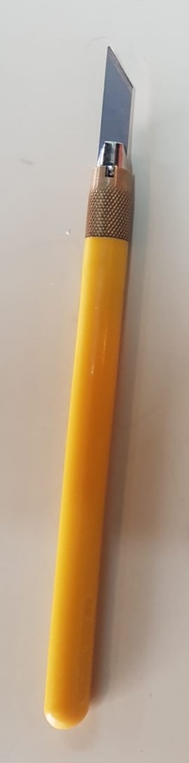
Useful tools also add the multimeter on the buzzer mode.
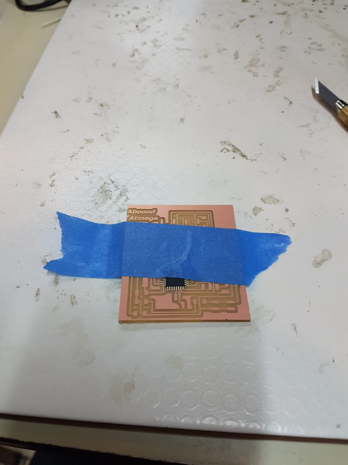
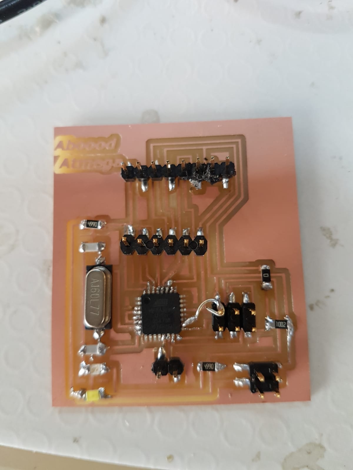
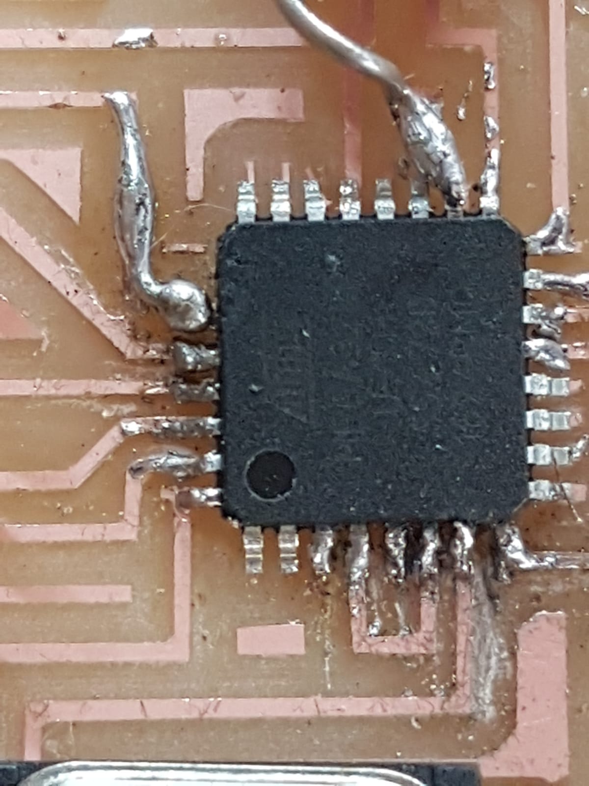
I added a tape because the atmega has small pins which are hard to solder so any movement will effect the position of the chip.
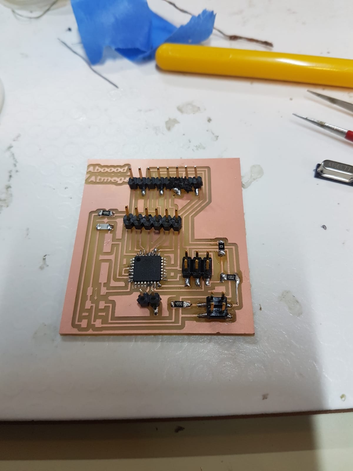
When I tryed to program my board it failed then I discovered that I did not creat a trace for the vcc for the atmega so I added a jumper.
Programming:
since the atmega is the same chip used in arduino board we can program the atmeg using arduino ide to read signals from the accelerometer and the ultrasonic sensor.
I connected the programmer AVRisp.

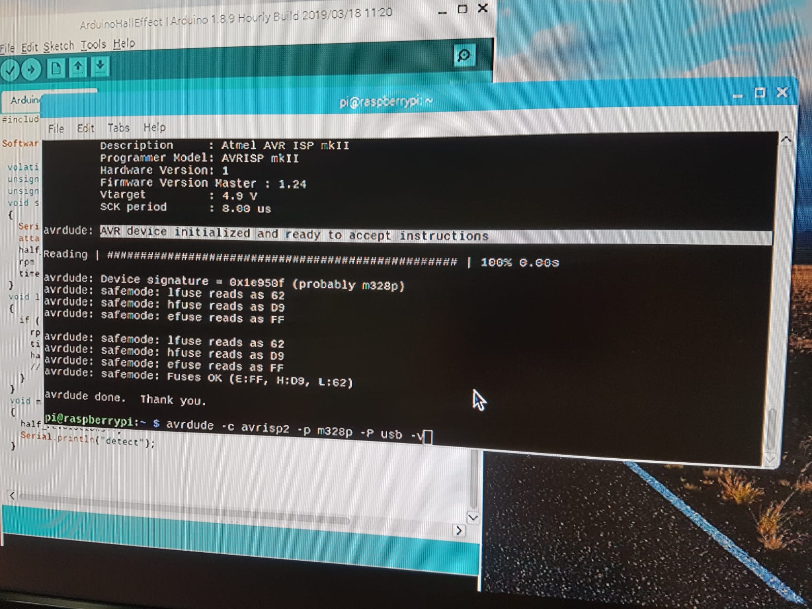
Using this command we can insure that our connections are connected properly.
avrdude -c avrisp2 -p m328p -p usb -v
I had an error that say that my connections are not complete.
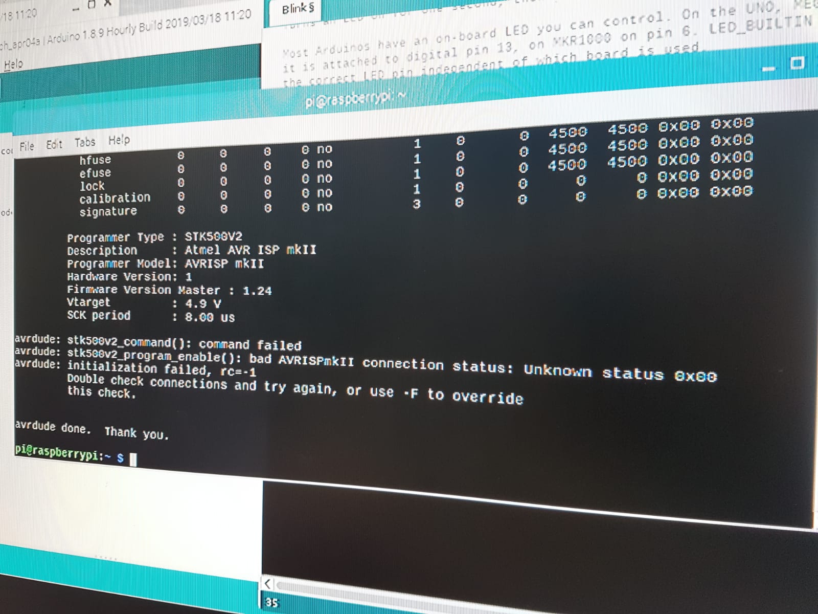
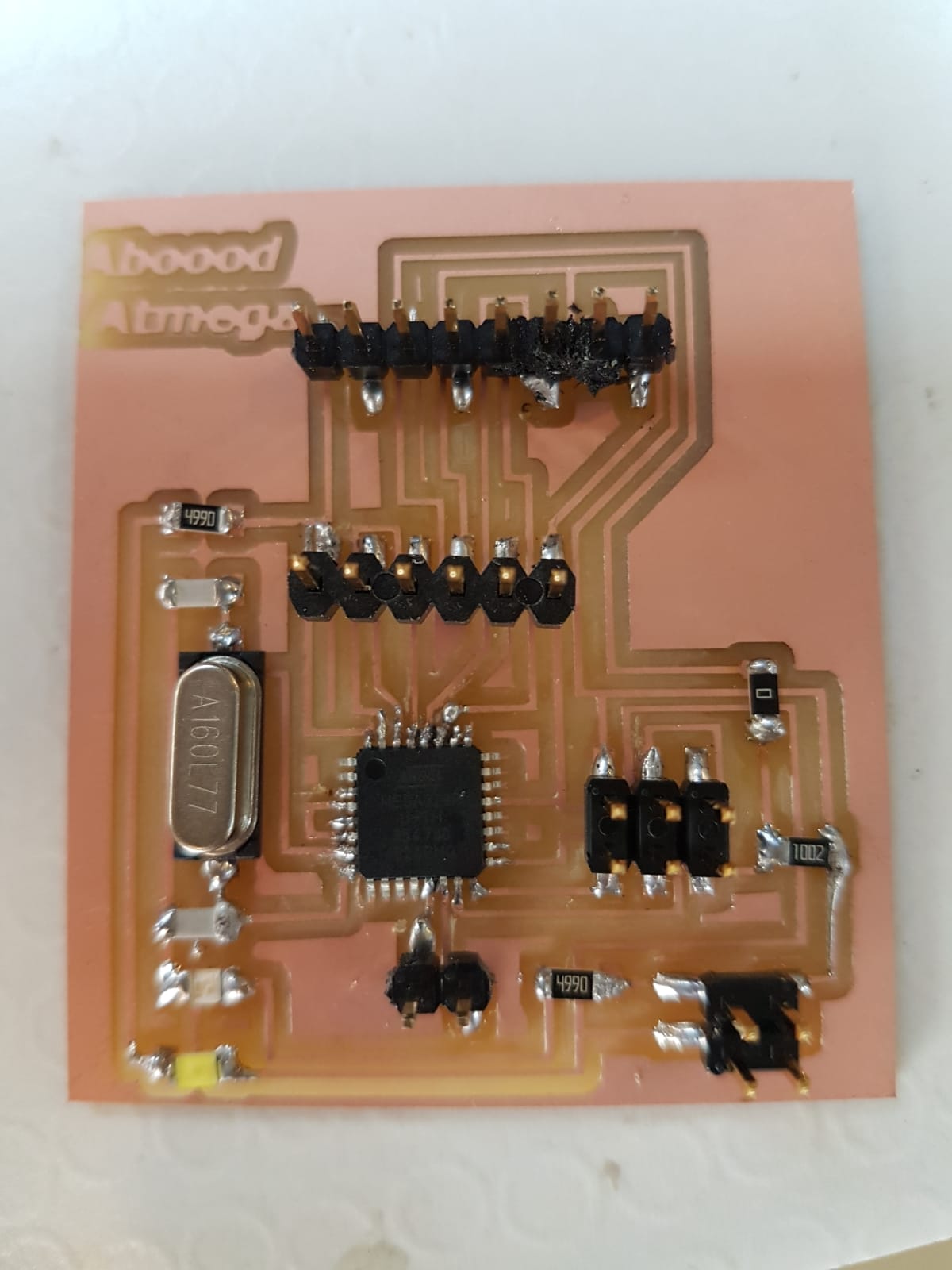
Using the multimeter buzzer mode I checked all my traces and found that some of the soldered traces for the atmega had a short circuit so I soldered them again and using the cutter I cleaned between the small pins.
Then I tryed again and it worked.
Then we had to set the fuses.
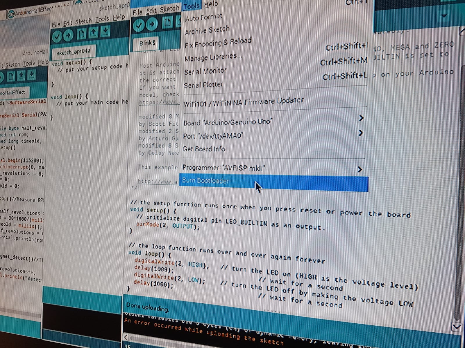
I used the blink example to test if the board can be programmed.

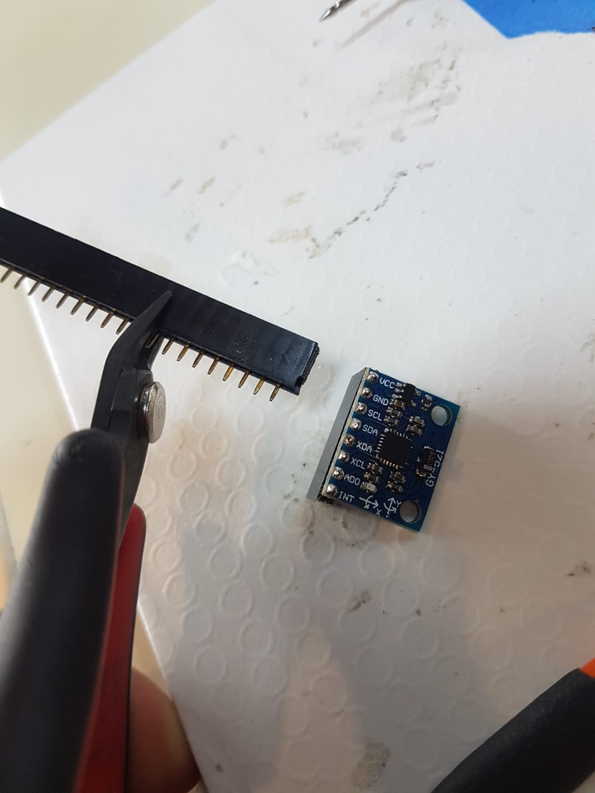
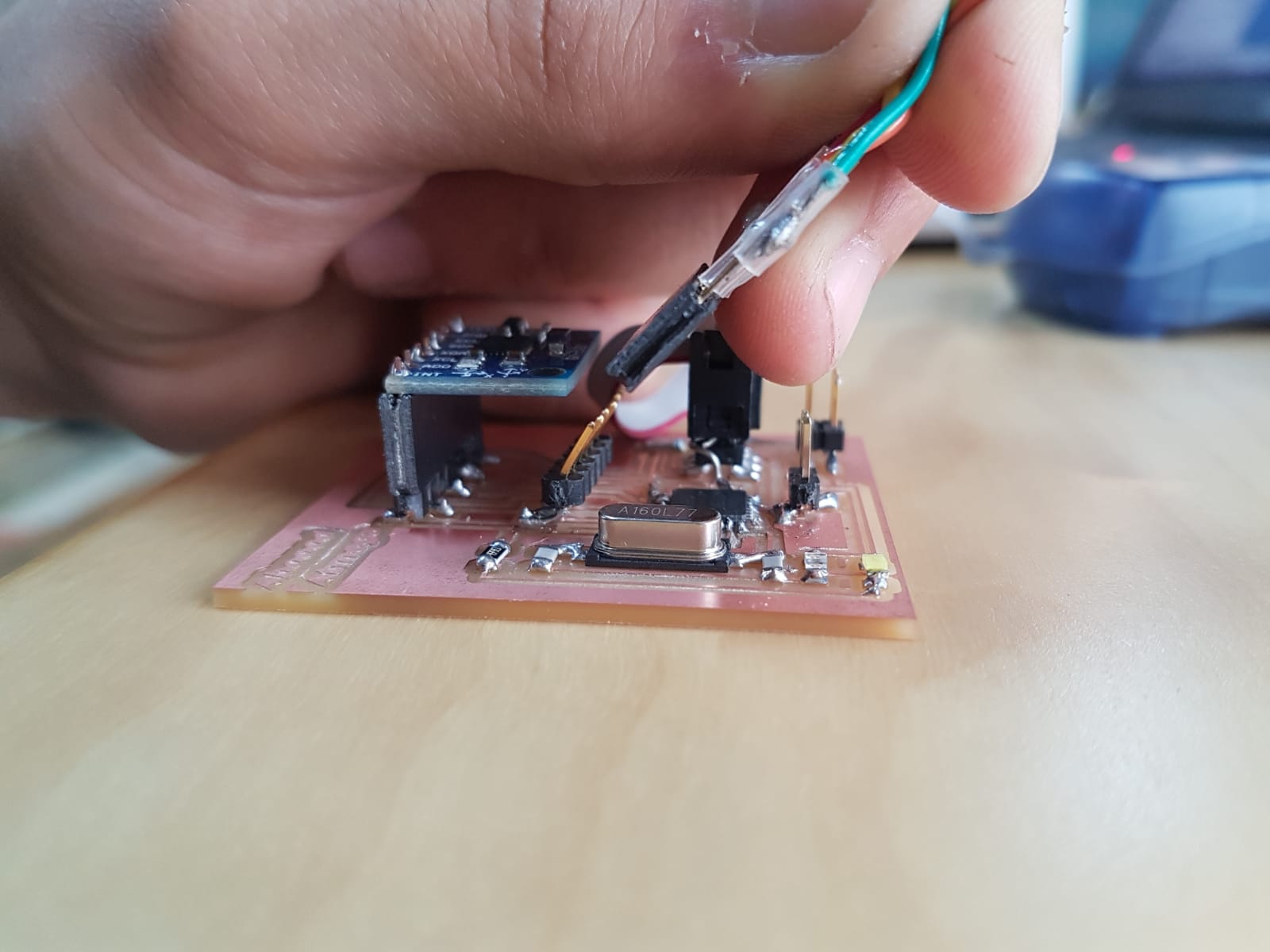
After that I soldered a female pins to the accelerometer. Note that we didnt have 8 pin female header so I took a longer one and cut it at pin 9 as it is a sacrifcing pin.
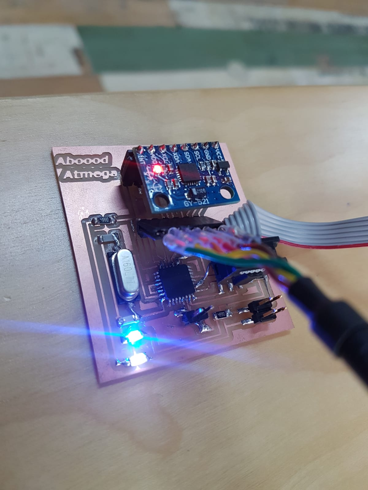
I didnt try to imagine how the connections will look like so I ended having no space for the accelerometer board. The solution was to bend the programming pins “FTDI-SMD-HEADER” to get a space for the accelerometer board.
Problem:
While I was debugging why the sensors was not working I connected a stepper motor to my board and it worked.

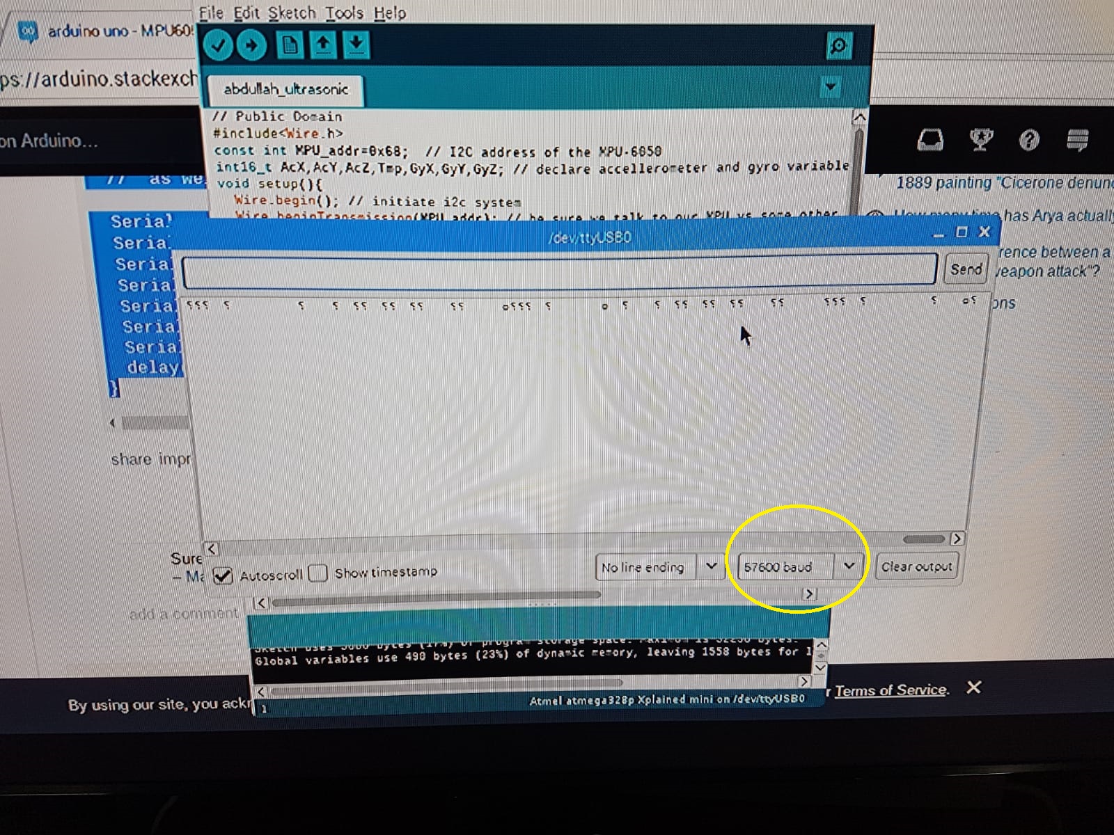
I was using the wrong baud rate it should be 9600. In addition some connections went lose and I was not able to programm the board. So in week12 I made a board that can host both input and output devices.
I started with the accelerometer.
Then the ultrasonic sensor.

code:
Blink
void setup() {

  pinMode(2, OUTPUT); //My bord LED is connected to pin 2
}


void loop() {
  digitalWrite(2, HIGH);   // turn the LED on (HIGH is the voltage level)
  delay(1000);                       // wait for a second
  digitalWrite(2, LOW);    // turn the LED off by making the voltage LOW
  delay(1000);                       // wait for a second
}
Stepper motor
#include <Stepper.h>
#define STEPS 2038 // the number of steps in one revolution of your motor (28BYJ-48)
Stepper stepper(STEPS, A5, 9,A4, 10); //set the stepper pins
void setup() {
  // nothing to do
}
void loop() {
  stepper.setSpeed(10);//  rpm
  stepper.step(2038); // do 2038 steps -- corresponds to one revolution in one minute
  delay(1000); // wait for one second

}
Accelerometer
#include<Wire.h>
const int MPU=0x68;
int16_t AcX,AcY,AcZ,Tmp,GyX,GyY,GyZ;

void setup(){
  Wire.begin();
  Wire.beginTransmission(MPU);
  Wire.write(0x6B);
  Wire.write(0);
  Wire.endTransmission(true);
  Serial.begin(9600);
}
void loop(){
  Wire.beginTransmission(MPU);
  Wire.write(0x3B);
  Wire.endTransmission(false);
  Wire.requestFrom(MPU,12,true);
  AcX=Wire.read()<<8|Wire.read();
  AcY=Wire.read()<<8|Wire.read();
  AcZ=Wire.read()<<8|Wire.read();
  GyX=Wire.read()<<8|Wire.read();
  GyY=Wire.read()<<8|Wire.read();
  GyZ=Wire.read()<<8|Wire.read();

  Serial.print("Accelerometer: ");
  Serial.print("X = "); Serial.print(AcX);
  Serial.print(" | Y = "); Serial.print(AcY);
  Serial.print(" | Z = "); Serial.println(AcZ);

  Serial.print("Gyroscope: ");
  Serial.print("X = "); Serial.print(GyX);
  Serial.print(" | Y = "); Serial.print(GyY);
  Serial.print(" | Z = "); Serial.println(GyZ);
  Serial.println(" ");
  delay(333);
}
Ultrasonic sensor
const int trigPin = 9;
const int echoPin = 10;
// defines variables
long duration;
int distance;
void setup() {
  pinMode(trigPin, OUTPUT); // Sets the trigPin as an Output
  pinMode(echoPin, INPUT); // Sets the echoPin as an Input
  Serial.begin(9600); // Starts the serial communication
}
void loop() {
  // Clears the trigPin
  digitalWrite(trigPin, LOW);
  delayMicroseconds(2);
  // Sets the trigPin on HIGH state for 10 micro seconds
  digitalWrite(trigPin, HIGH);
  delayMicroseconds(10);
  digitalWrite(trigPin, LOW);
  // Reads the echoPin, returns the sound wave travel time in microseconds
  duration = pulseIn(echoPin, HIGH);
  // Calculating the distance
  distance = duration * 0.034 / 2;
  // Prints the distance on the Serial Monitor
  Serial.print("Distance: ");
  Serial.println(distance);
}
Downloads:
(( Note that I forgot to add vcc to the atmega >> add jumper ))
Download board component image
Recommend this link for arduino setup.