14. Networking and communications
In this week we will try a communication method between microcontrollers which is I^2C.
Group Assignment
Understanding :
This how our connection will look like. In addition both microcontrollers has to be connected to VCC and GND.

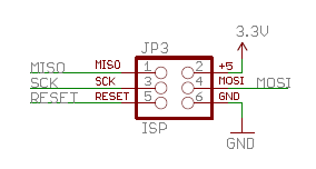
My first board “Master” has attiny44 20 MHZ clock and I can connect the SDA and SCL through the avr isp header.

My second board “Slave” has atmega328p and I can connect the SDA and SCL through PC4 and PC5.

I will be controlling my slave board LED using the master board button.
Programming :
To download the attiny board use this link
To download the wire.h library use this link

Slave code:
#include <Wire.h>
#define led 2
void setup() {
Wire.begin(8);
Wire.onReceive(receiveEvent);
pinMode(led, OUTPUT);
}
void loop() {
delay(100);
}
void receiveEvent(int howMany) {
int x = Wire.read();
if (x == 1)
{
digitalWrite(led, HIGH);
}
if (x == 0)
{
digitalWrite(led, LOW);
}
}

Master code:
#include <SoftwareSerial.h>
#include <Wire.h>

#define button 2

void setup() {
Wire.begin();
pinMode(button, INPUT);
}
void loop() {
int data;
data = digitalRead(button);
if (data == 1)
{
Wire.beginTransmission(8);
Wire.write(1);
Wire.endTransmission();
}
else {
Wire.beginTransmission(8);
Wire.write(0);
Wire.endTransmission();
}
}
Then connect the SDA and SCL together and add a VCC with GND and the 4.7K resistors as shown in the first picture.
