Final Project
The story :
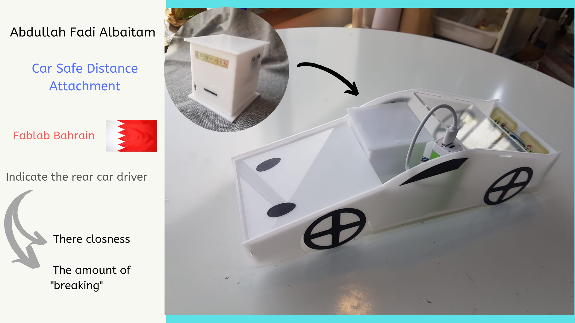
One day I was driving my car 120 km/h in the highway after a while the car in front of me pressed the breaks, but I didn’t give it the right attention because I couldn’t see that a traffic jam is in front of this car ,then he opened the hazard lights after that I had to press the breaks hard to keep a safe distance between the cars. Most accidents happen because we don’t keep a safe distance between our car and the front car. In addition, traffic jams are created because of the same reason. My project is an attachment attached to the cars so it can give more indication about the front car breaking. This attachment will reduce the number of accidents and traffic jams.
HOW ?
My system has four components two indicators (red break level light + red, yellow, green light) and two sensors(accelerometer + ultrasonic). The first system (red break level light + accelerometer) the red break level light is proportional to the accelerometer signal so if you pressed hard on the brake padel the level of red lights will increase. The second system (red, yellow, green light + ultrasonic) this system will give an indication for the back car about its distance relative to my car so the more the back car gets close to my car the more light will change from green “safe” to red “not safe”.
Steps :
(1) Sketch
In week 1. Principles and practices I started with trying to sketch or imagine my project :
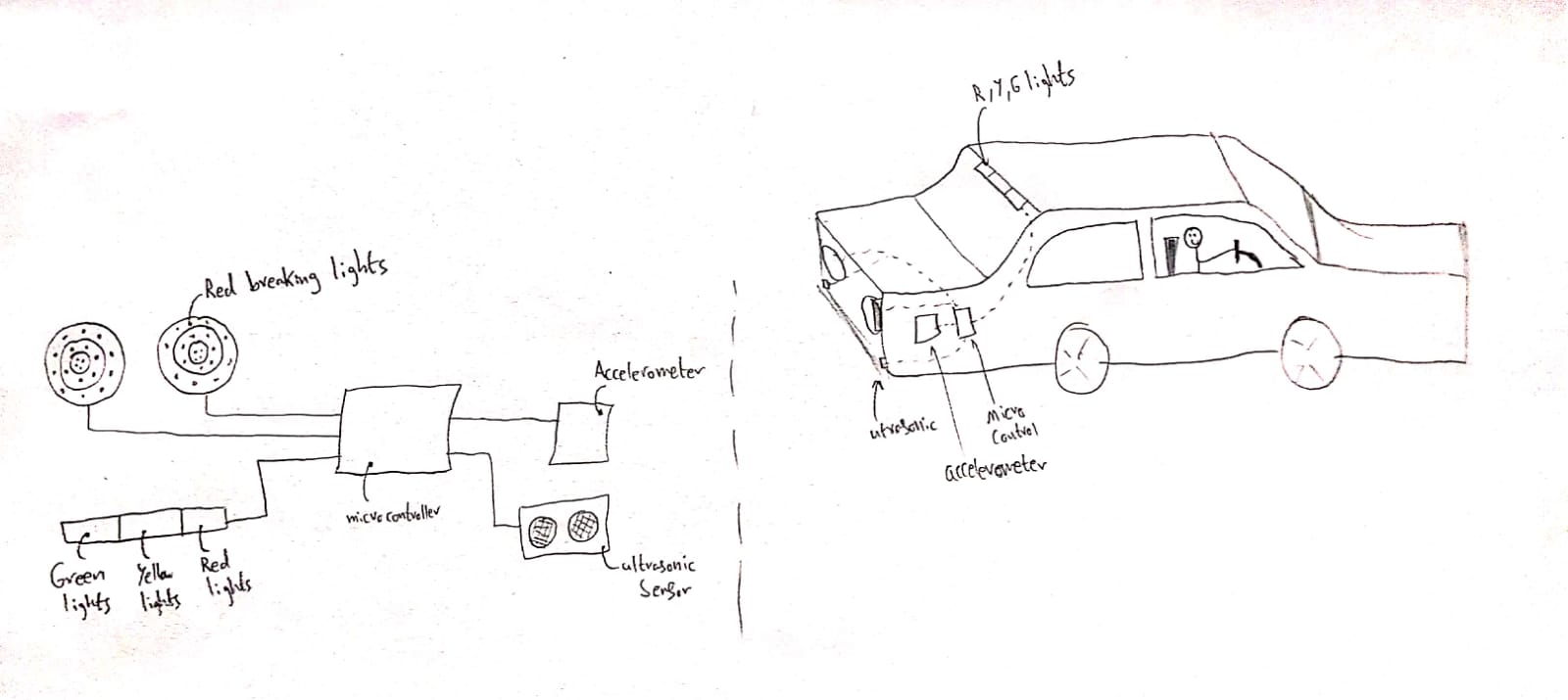
Now I know that I need two input devices “accelerometer ,ultrasonic” and two output lights “one to tell the rear car how close it is (red ,yellow ,green) withe the help of the ultrasonic sensor and the other to show how much breaking is pressed (red) with the help of the accelerometer. Furthermore I will need a microcontroller and a power source with some wires.
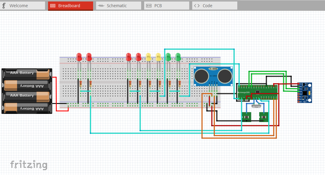
I have used fritzing software to wire my cicuit.
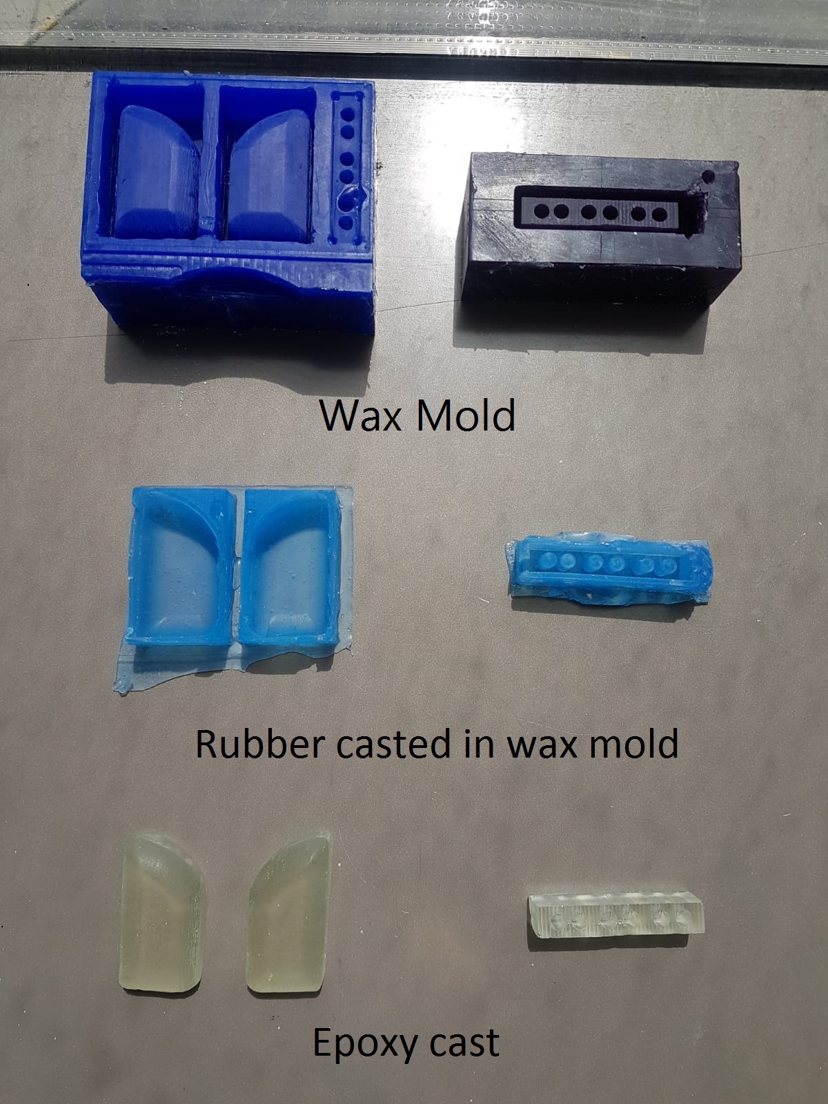
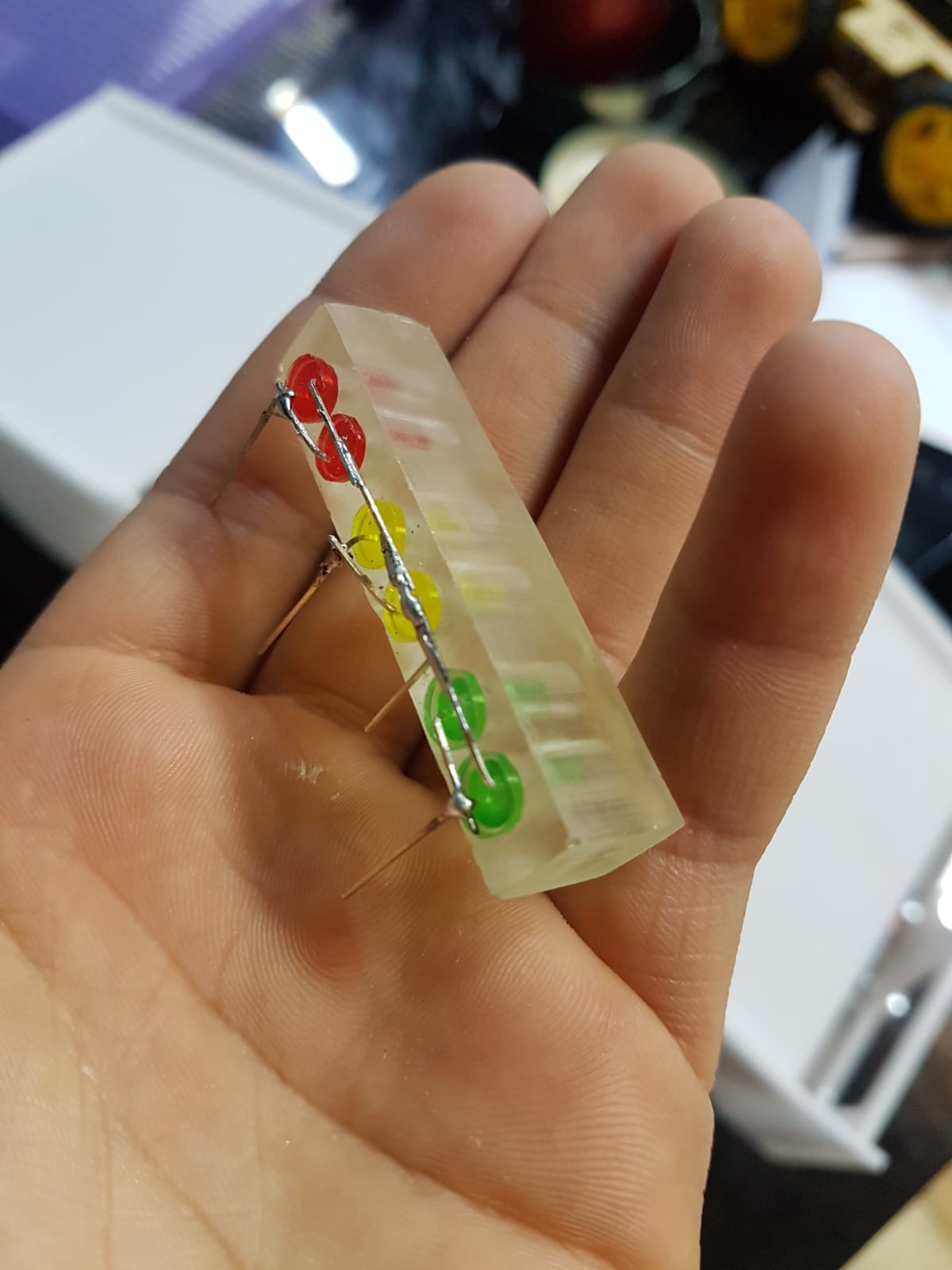
(2) Casting a cases for lights
In week 10. Molding and casting I made the case for the lights.
To download the 3D files click here
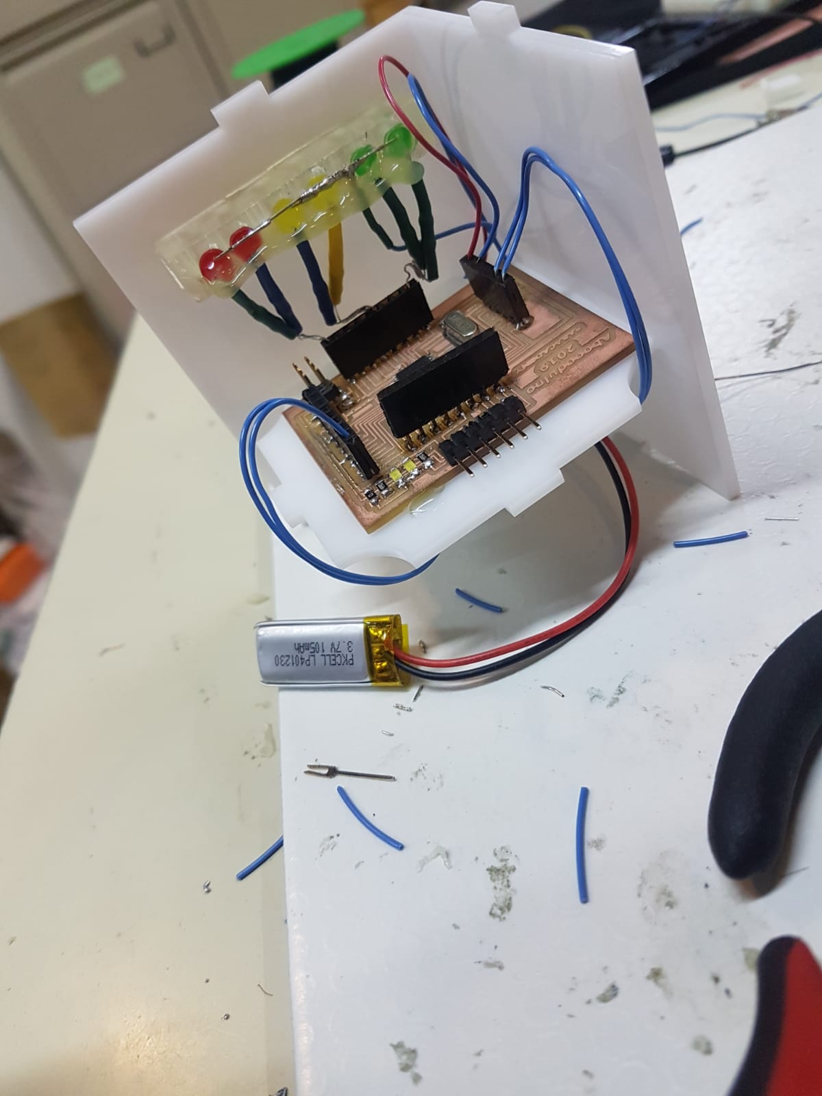
(3) Microcontroller
In weeks week 11. Input devices + week 12. Output devices I made a circuit that will host the sensors accelerometer and ultrasonic with the LEDs using Atmega328p microcontroller.
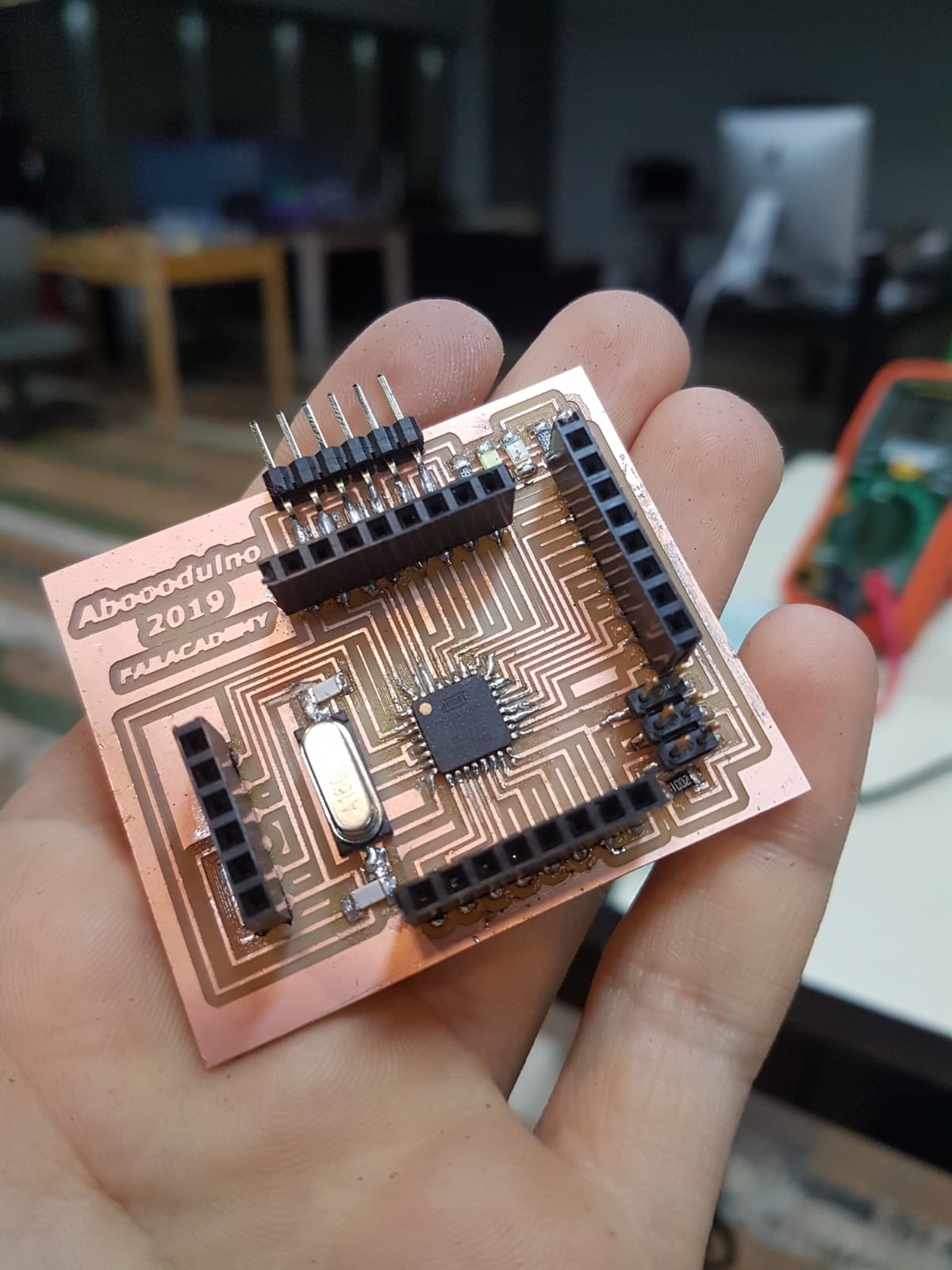
To download the circuit files click here
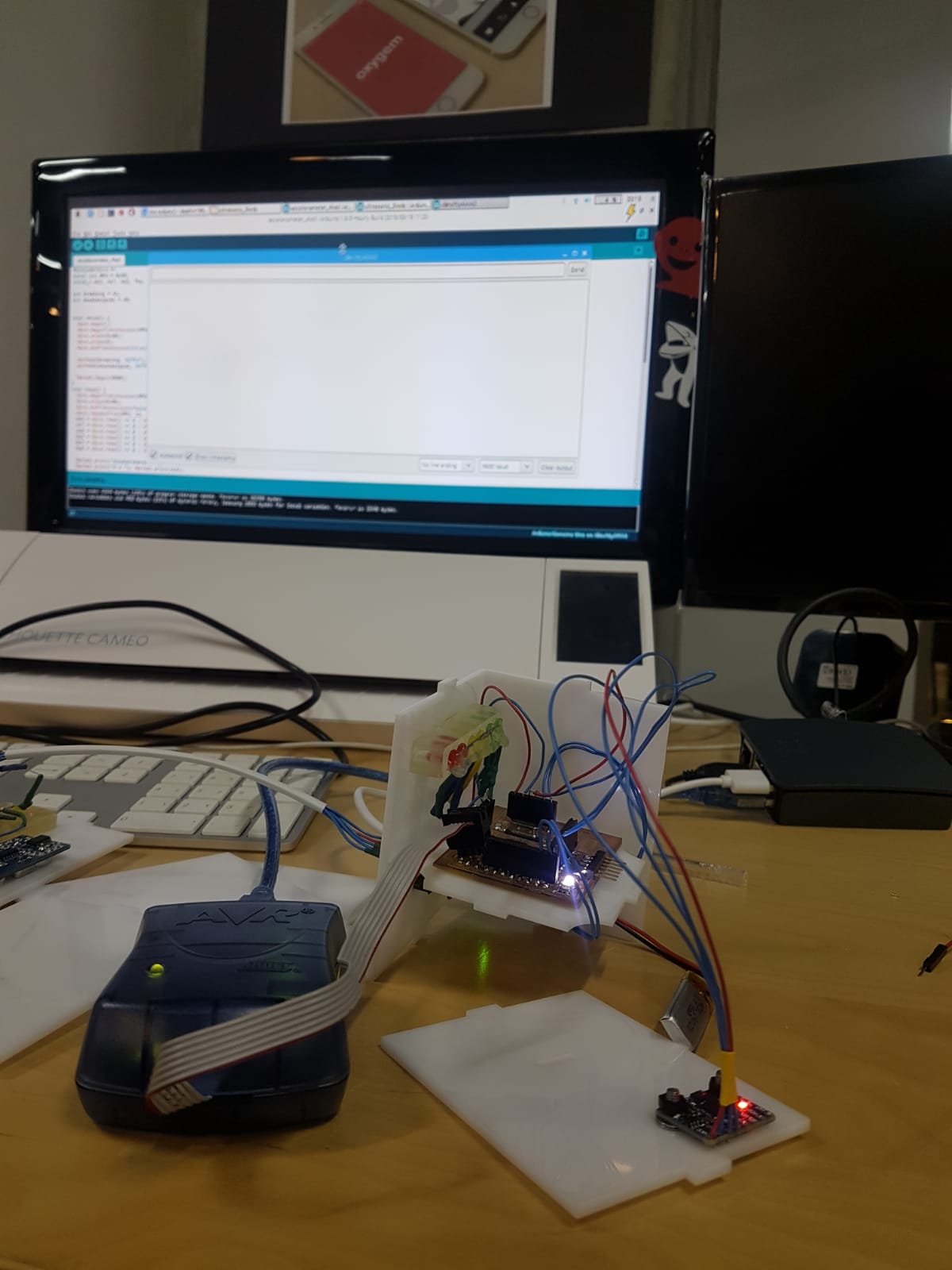
(4) Code
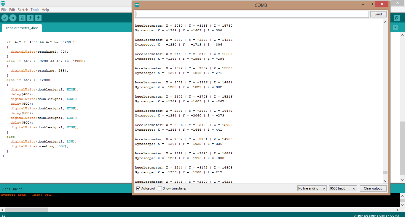
I made the code using arduino IDE then I tested the it using arduino board after that I used it in my microcontroller. First
This is the data that I optained. So I took the maximum value and the minmum one and the middle one and inserted them in my code
After that I had to run some tests on the accelerometer using my car. I was hitting the breakes hard to see what values should I change in my code “calibration”. Then I made a range for the ultrasonic sensor as three levels “Green Yellow and Red”

To download the code click here
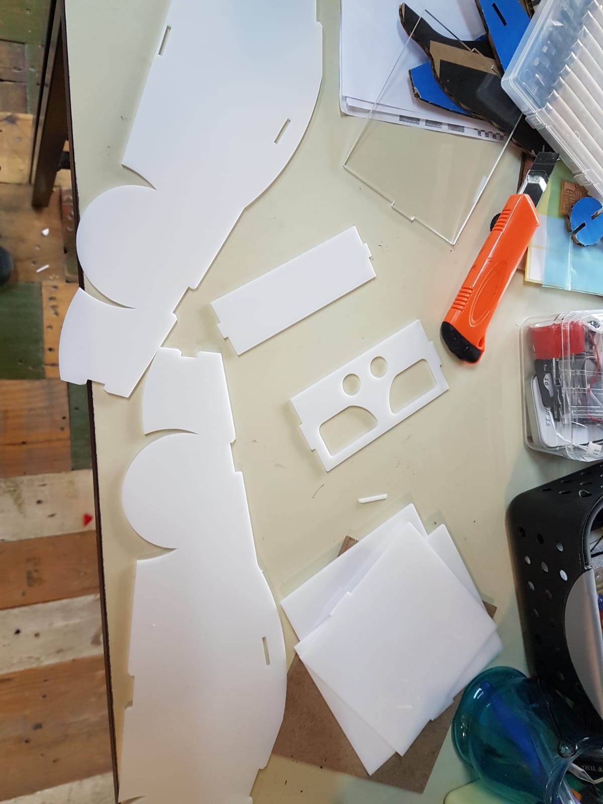
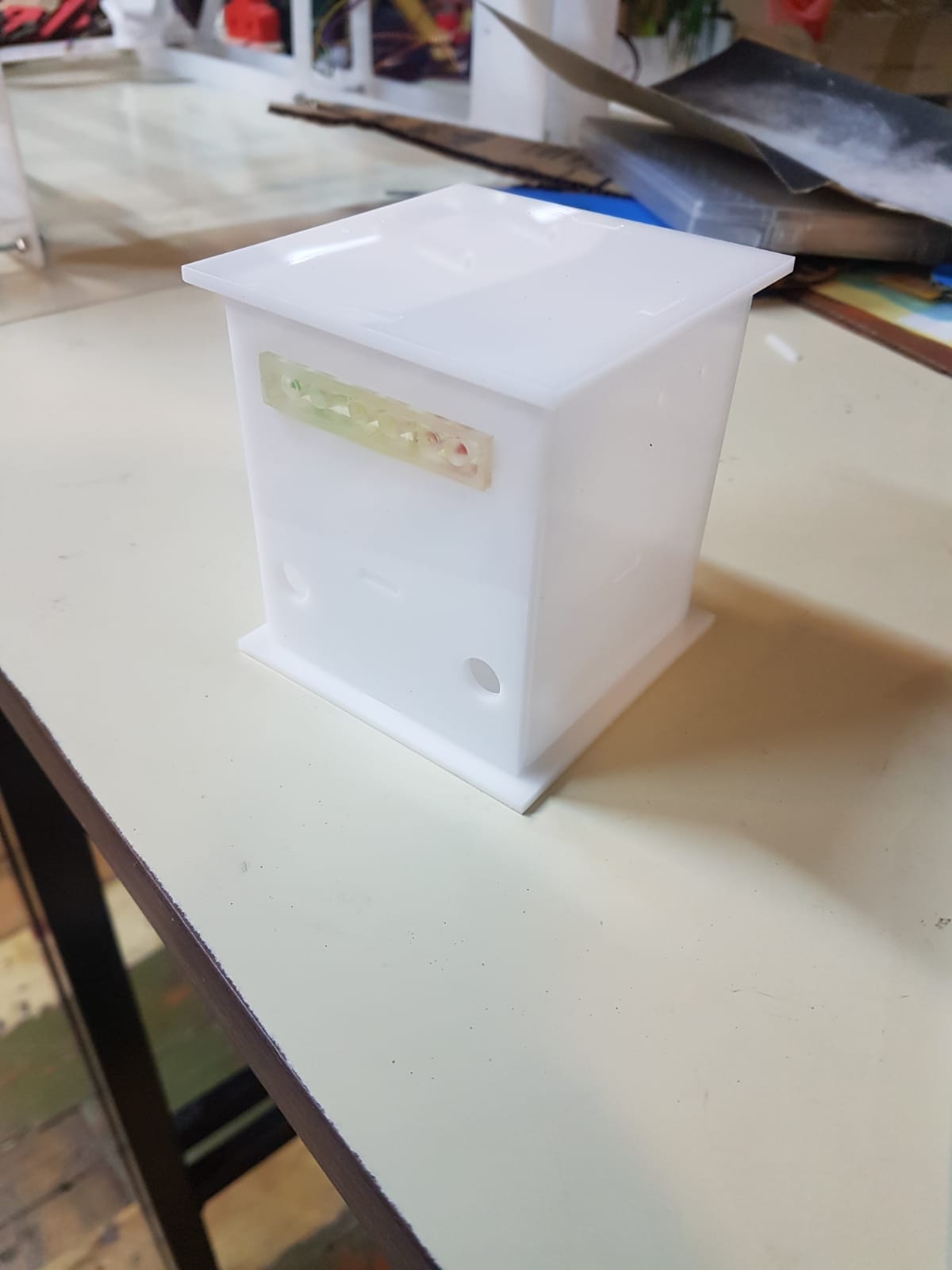
(5) Cutting a case and a car model
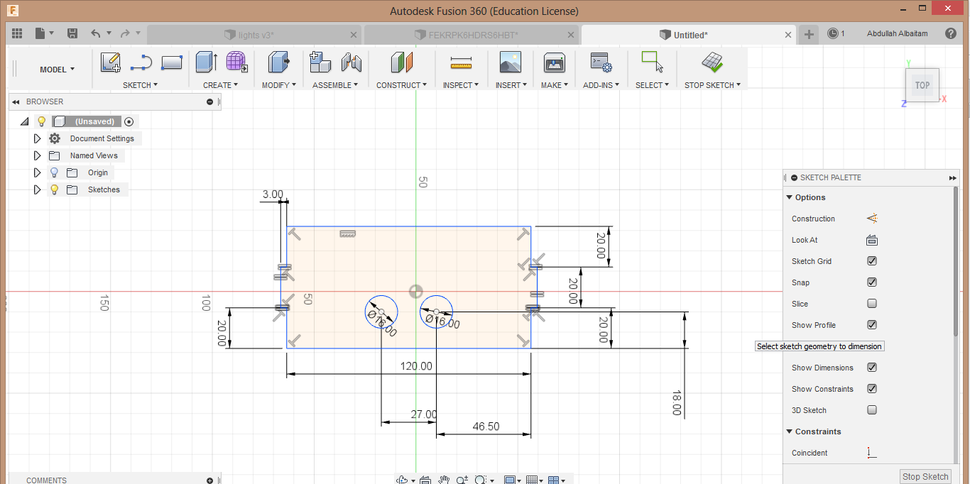
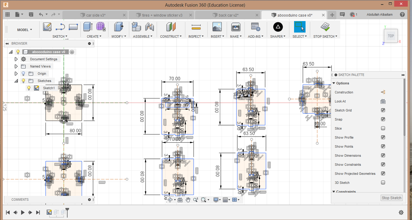
The steps in the laser cutter week 4. Computer controlled cutting helped me to cut the case for the microcontroller and the model of the car which I designed using fusion360 then exported the designs to SVG file using this link steps. I recommend this video to learn more about the constrians that I have used.
I started designing the back side of the car that will include the ultrasonic sensor and the rear lights cases. First I created rectagles then I added there dimensions using (D) after that using (T) I trimmed the unessesary lines After that I used (c) to create the circles and I added the parallel constrain to keep then in the same axis and the symetry tool to keep them symetrical.
By clicking on (s) I navigated for the mirror toll to mirror the lights case I took the exact measurments from my previos design in week 10. Molding and casting.
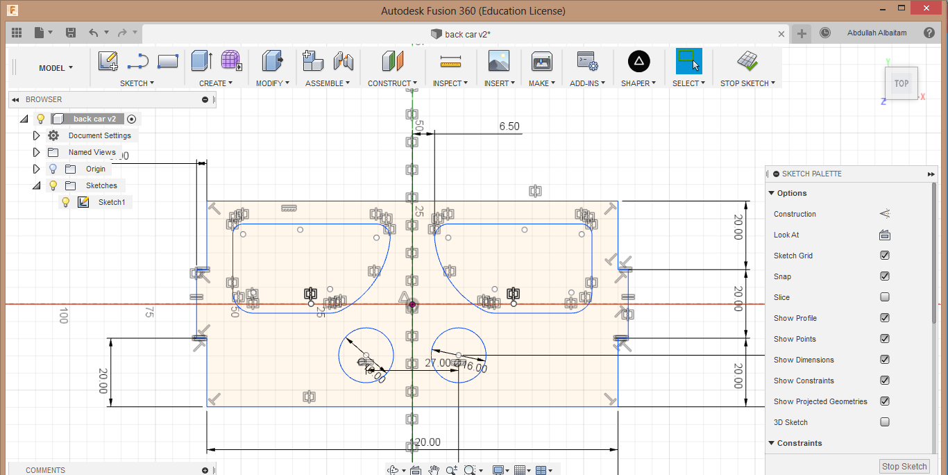
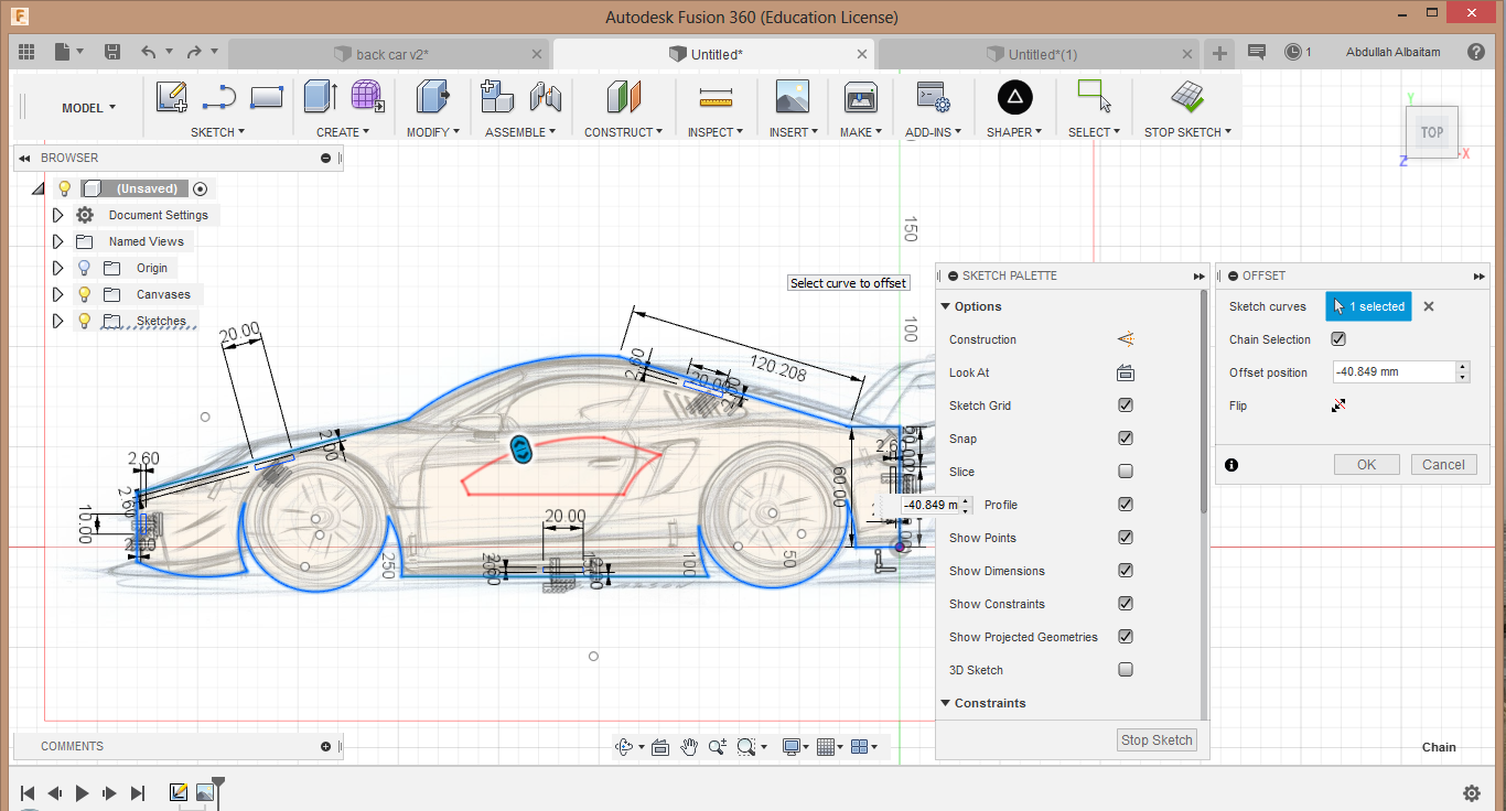
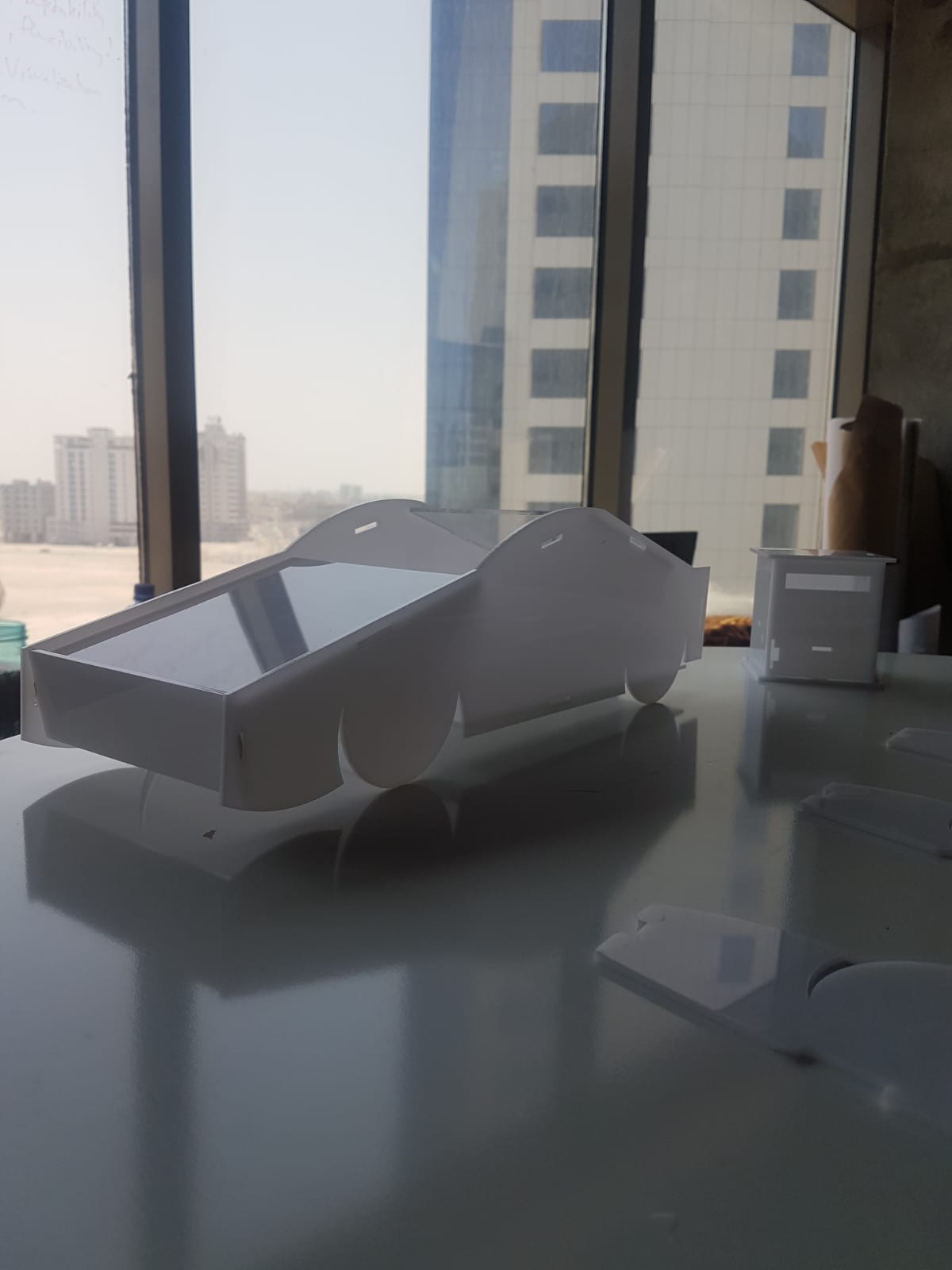
I imported a car sketch and then I trased the shape of it. I made the holes 2.5mm wide to hold tight the 3mm wide acrylic.
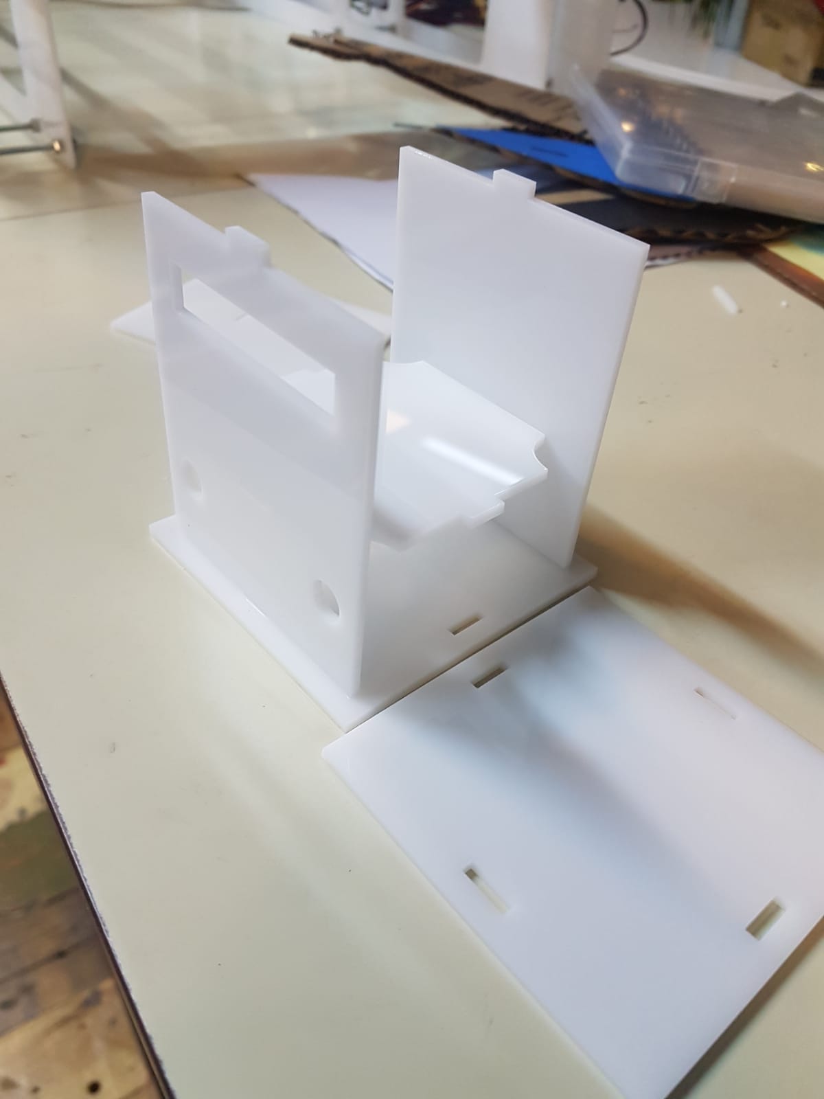
I wanted a flixible case because I had alot of wires so I made the plate that holdes the microcontroller bigger and it had holes in each corner so that I can have axis to the wires from any location.
Using the steps in week 4. Computer controlled cutting I started cutting the designs,
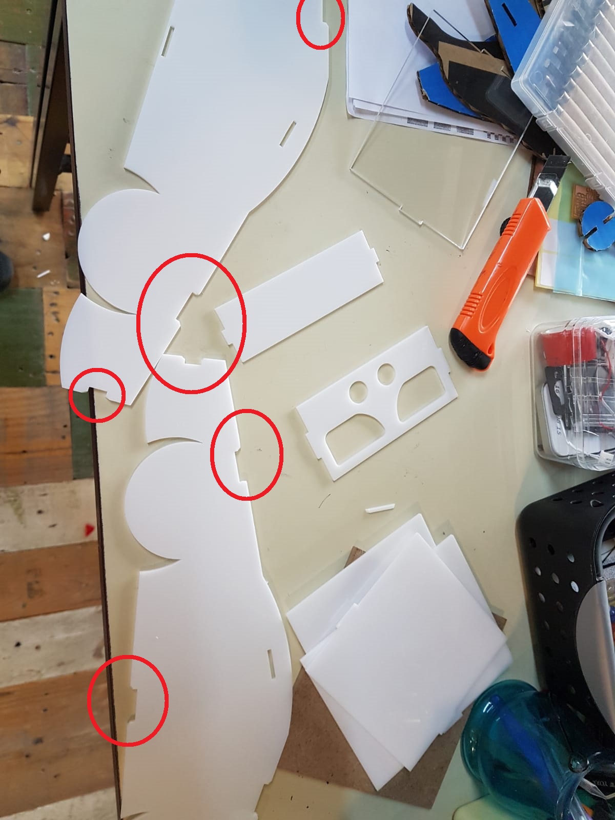
Problems
When I desined the holes that will hold the other parts I didnt leave enough gap between it and the corners so they broke I changed the design to a gap = 5mm.
After cutting the back side the ultrasonic sensor didnt fit so I changed the design.
To download the case and car model SVG files click here
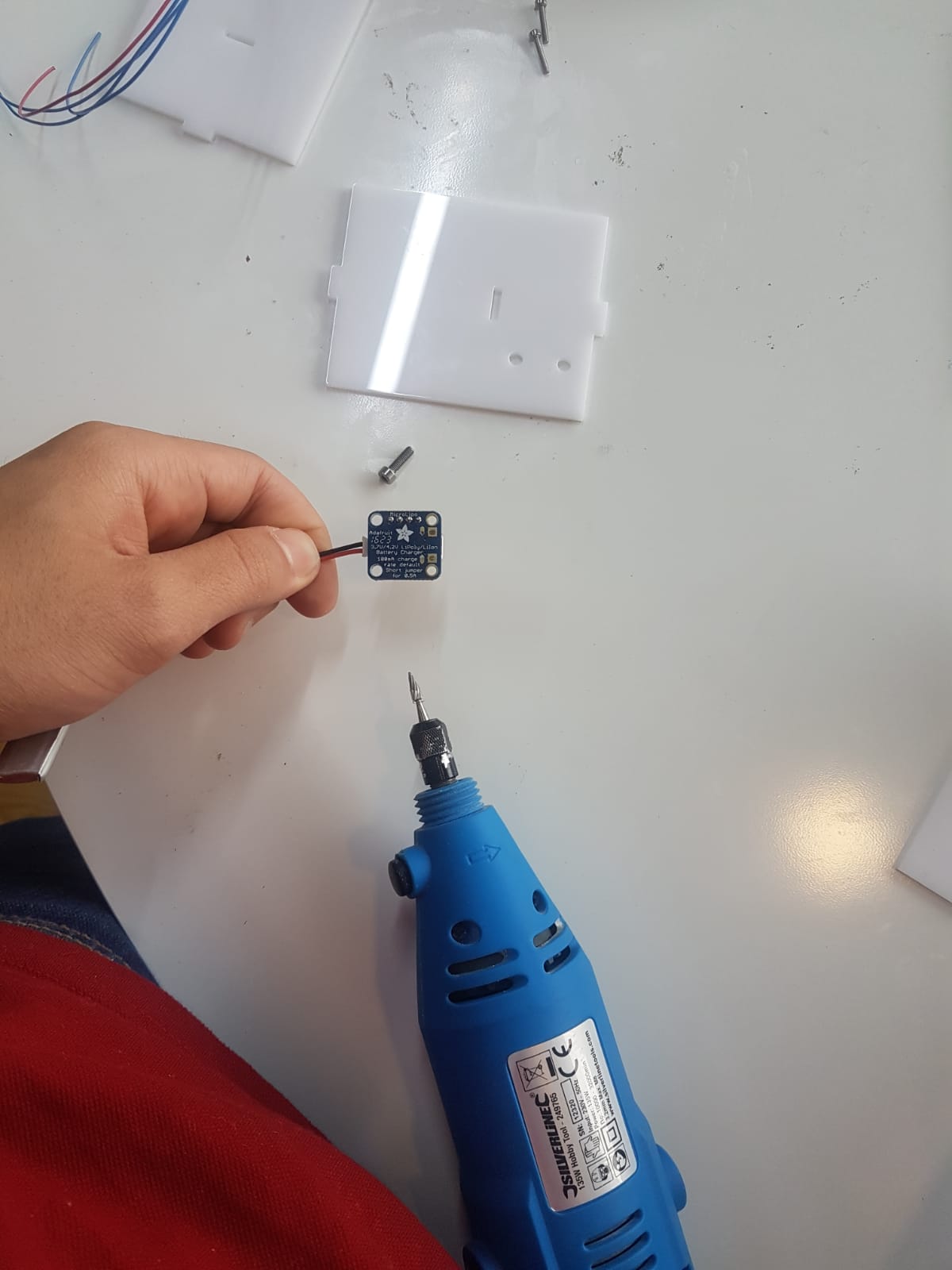
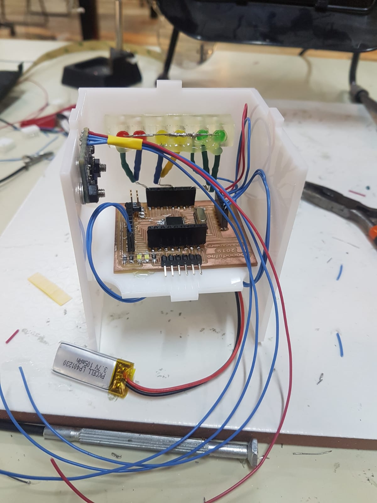
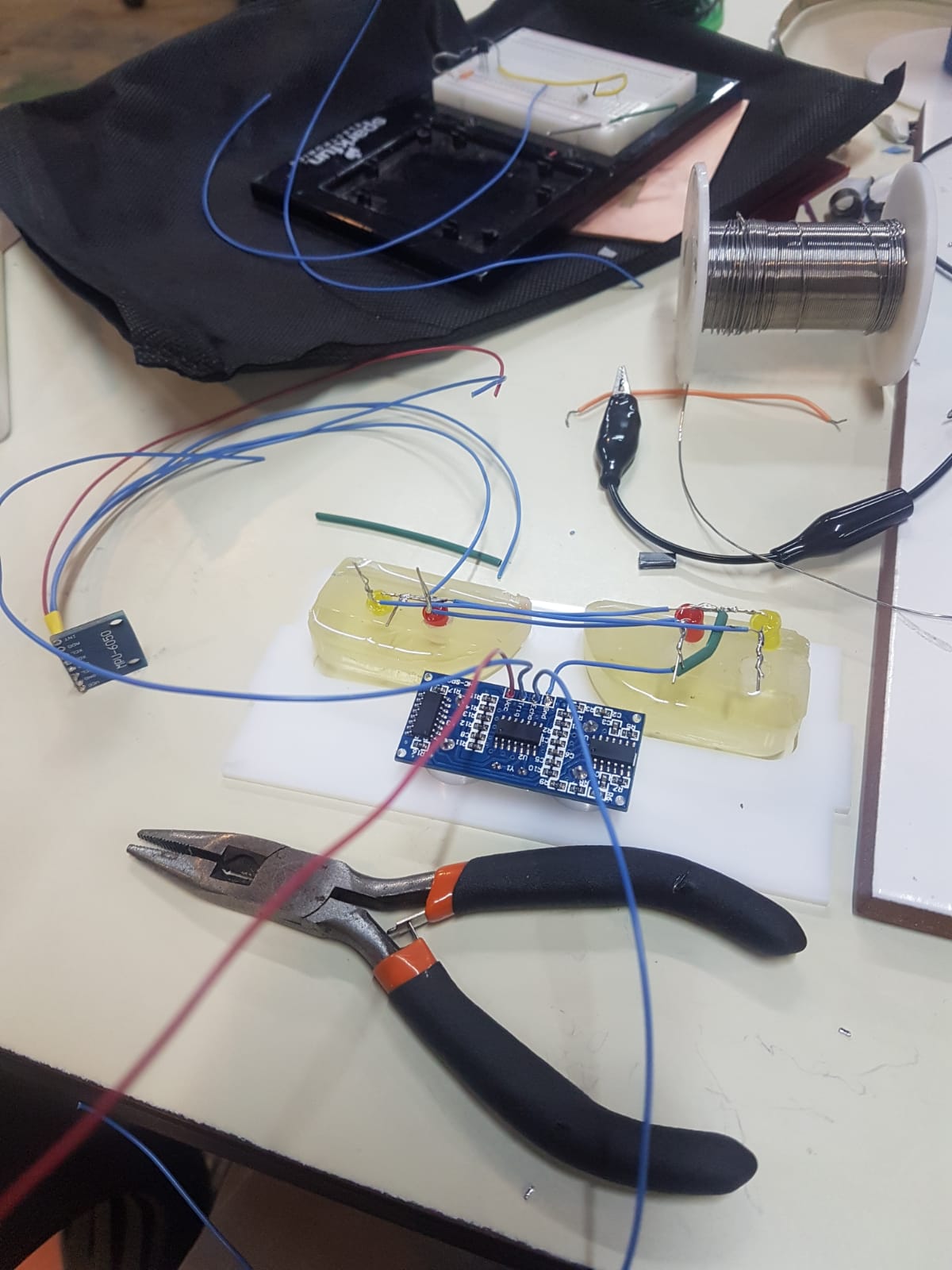
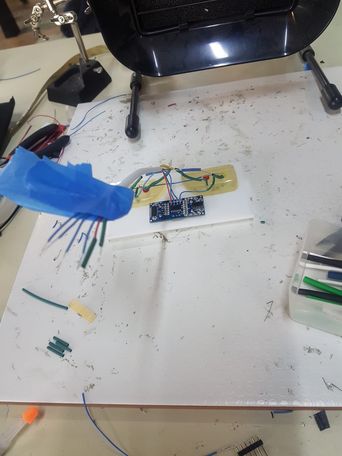
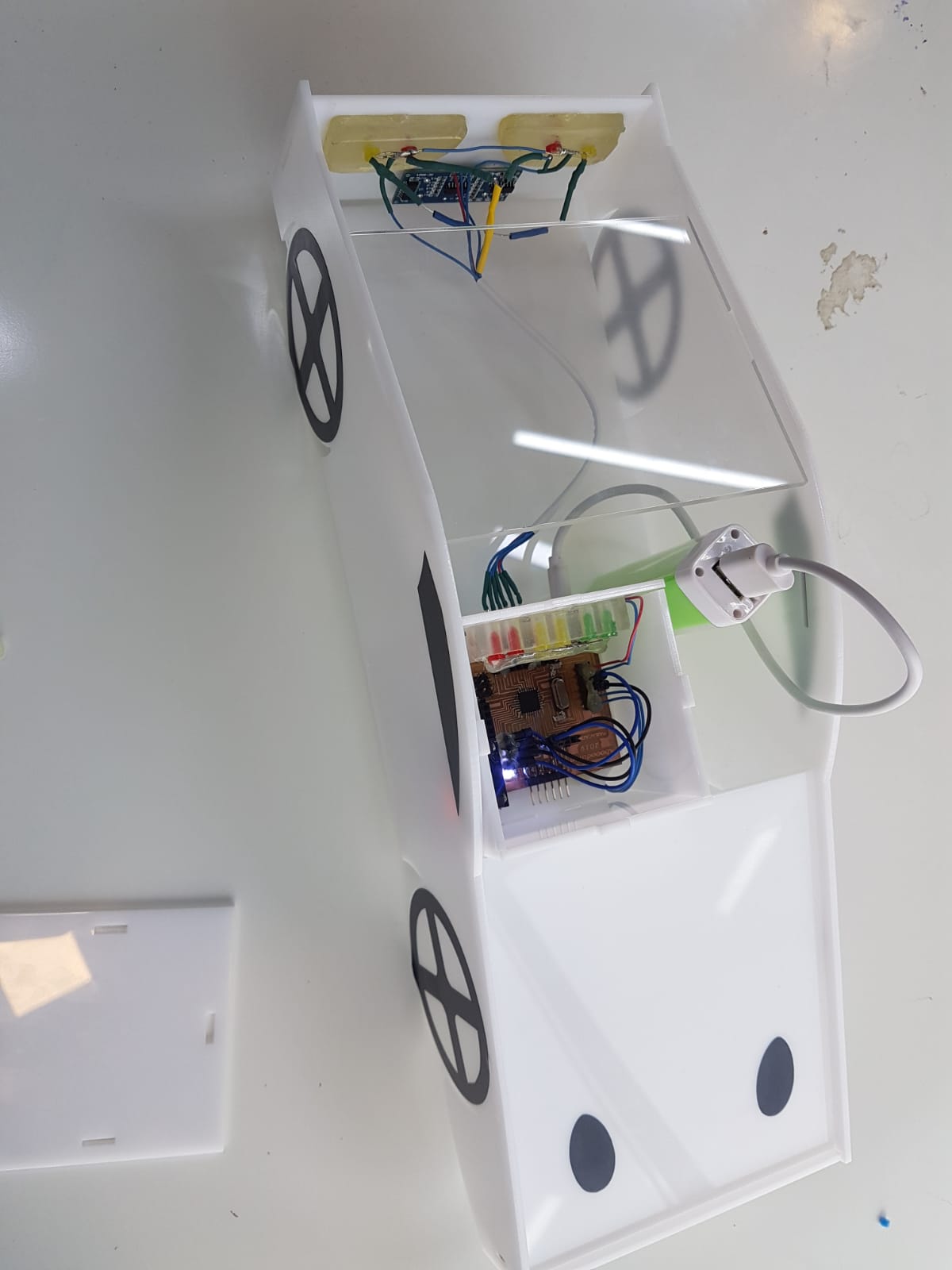
(6) Electronics
Then I started placing the electronics and the epoxy cases for the lights all in its place.
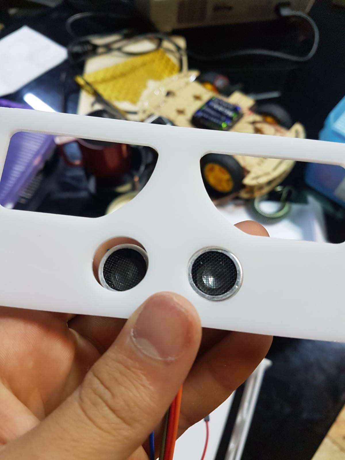
Ultrasonic gap indicator
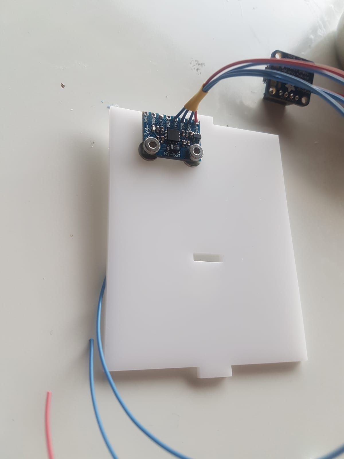
Accelerometer
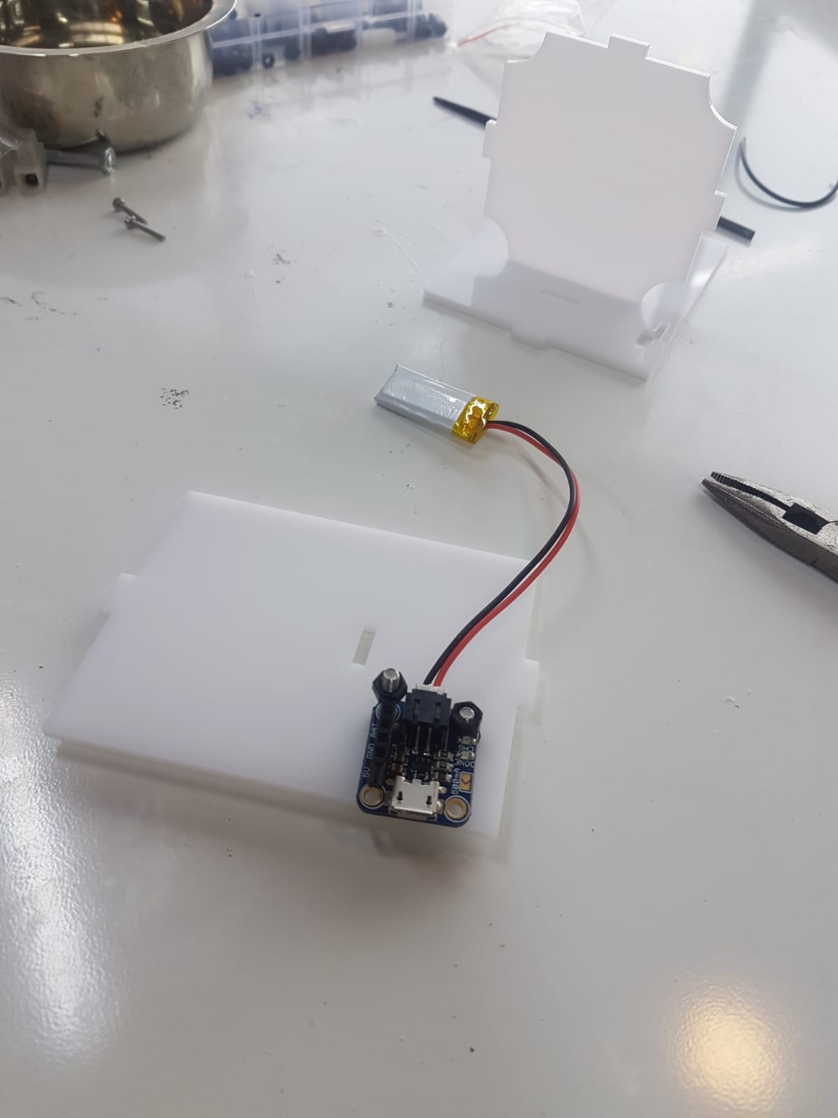
The power input circuit I made the holes bigger using a drill
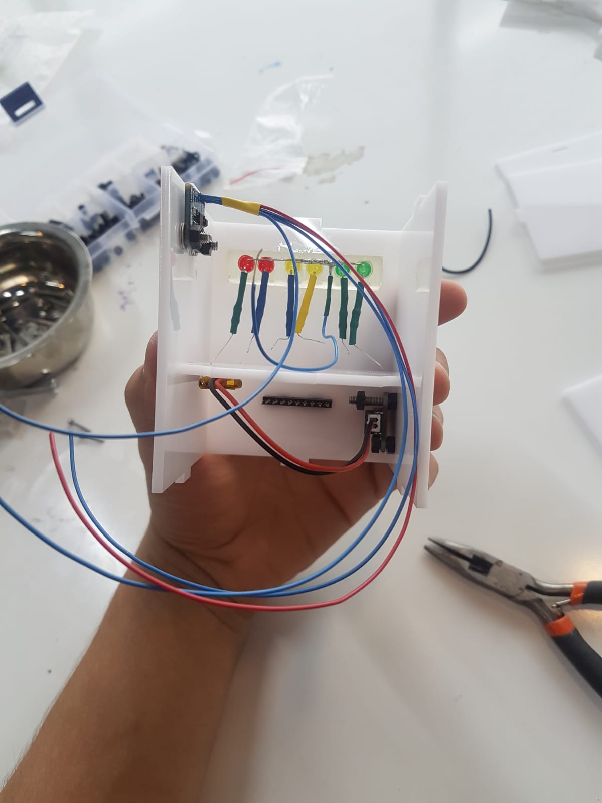
Here is the tricky part were you need to see the nearest pin on the board to your sensor or the lights. In this part designing holes in each corner of the middle plate helped me alot in wiring everything.
Then I uplloaded my program to my board
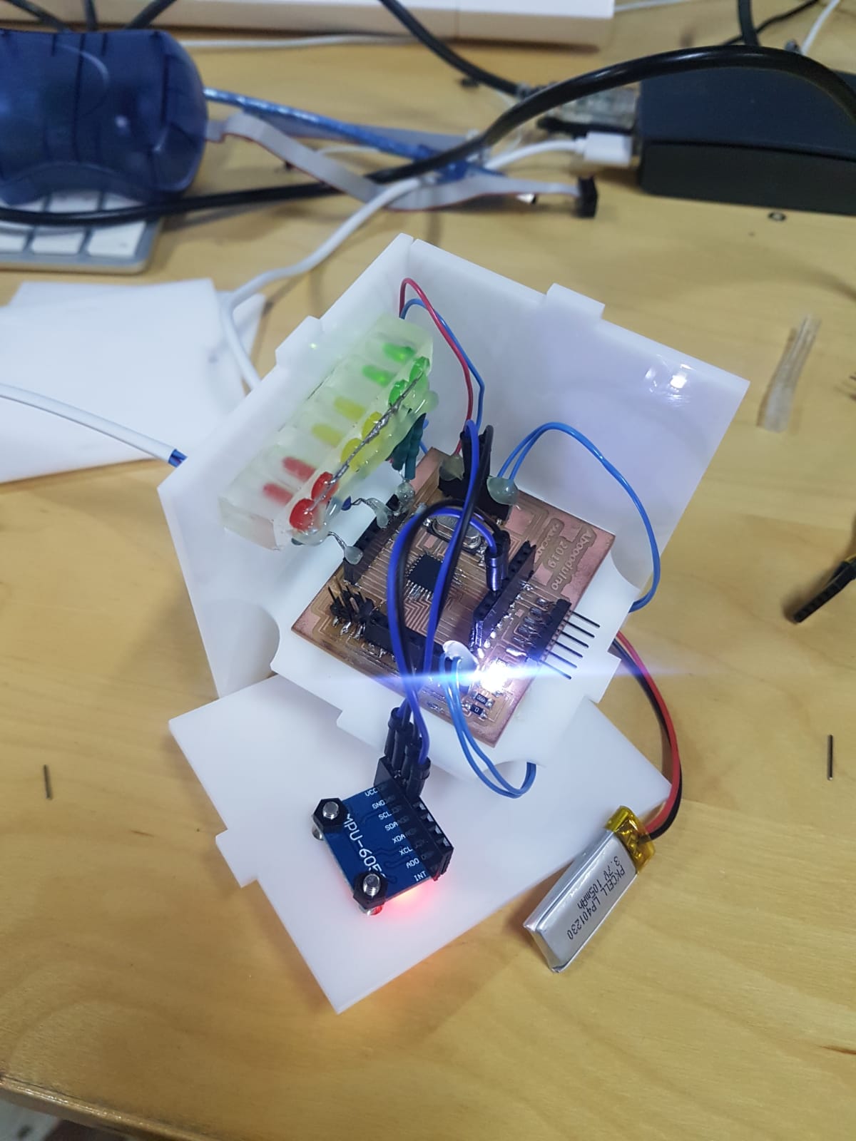
After I finished the case I started working on the back side of the model
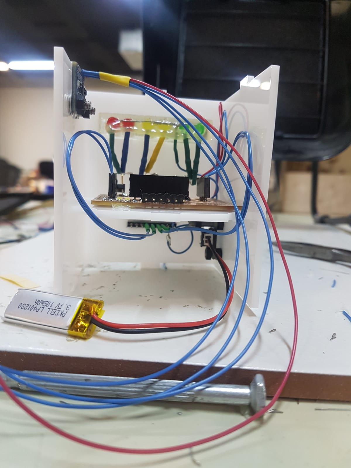
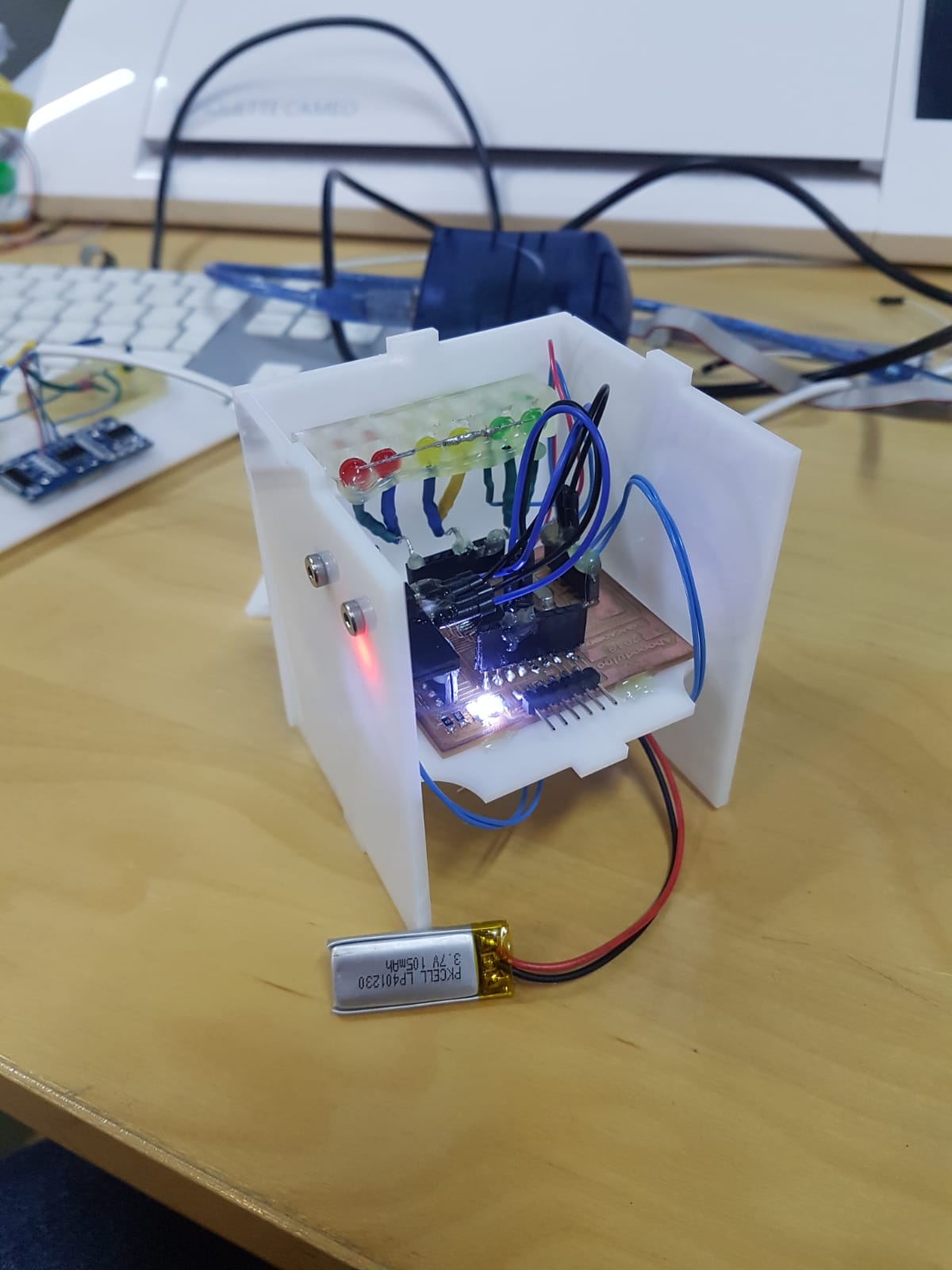
Then I tested my system before closing everything
Problems
When I was screwing my accelerometer I accedently broke a part from it. However I tested it and it didnt work so we had to change it.
While I was connecting my wires the female piece came off so I resoldered the pins.
(7) Cutting stickers
I added some stickers which I made in week 4. Computer controlled cutting

To download the Stickers DXF files click here
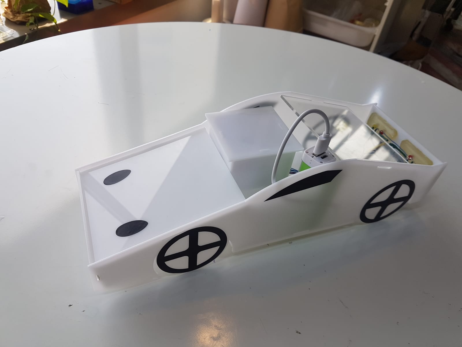
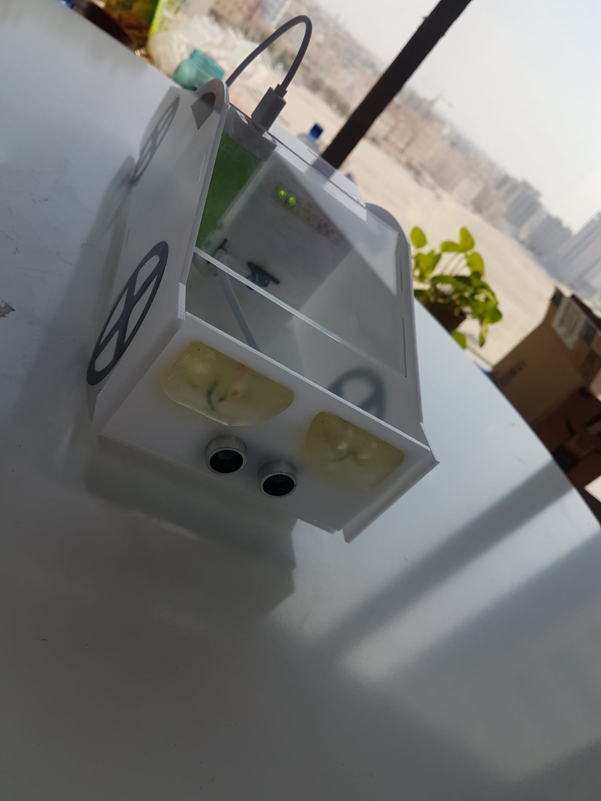
Its done !! this device will be as an attachment for the cars to give the rear car driver an indication of there closness to the car and it the break was hit hard it will automatically turn the danged lightes and increase the red light brightness.
The closness system

The emergency break system

Cost :
| week | Name | Total Price “$” ‘BHD’ | Description |
|---|---|---|---|
| 10 | Mold1+2 and epoxy cast | ” 2 ” ‘ 1 ‘ | Made the case for the LEDs |
| 11 | Input components | ” 2 ” ‘ 1 ‘ | Input sensors (Accelerometer + Ultrosonic) |
| 12 | Output components | ” 1 ” ‘0.4’ | Output LEDs |
| 11+12 | Microcontroller | “17.5” ‘6.5’ | To controll everything |
| 4 | Case and car model | ” 2 ” ‘ 1 ‘ | To keep everything in place |
| Electronics | ” 1 ” ‘0.4’ | Power circuit and power bank | |
| Others | ” 4 ” ‘1.5’ | Wires + Screws M3 + Resistors 500ohm |
Total cost : 29.5 $ 11 BHD
For more details on Microcontroller price see week 11. Input devices
whos done what before ?
There are some Ideas in the market that are similar to my system. for example tesla cars can detecte two cars ahead and it dont just indicate the breaking it also stops automatically see this experment video.Here is a link that explaines the automatic breaking. In addition this is a product that gives signes for the rear car driver. Another system made by general motors General Motors Following Distance Indicator Technology that gives you indication of how close you are from the front car. Another amazing product that tells the rear car driver of there closness by drawing a laser line behind the car. Moreover most of the new cars have automatic danger light indicator when the car decelarate at a hard rate.
what makes my attachment unique is that it combines two systems in one piece.
3D view
Using Autodesk Photo Recap which I used in week 6. 3D Scanning and printing I made a 3D model of my project.

Safe distance
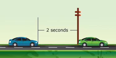
For more details click here
Acknowledgment
Note that when I wrote the code I started by taking the standard examples of blink, Ultrasonic and Accelerometer.
license

This work is licensed under a Creative Commons Attribution 4.0 International License.