11. Input Devices (Apr 03)
This week we were suggested to measure the analog and digital signals in an input device for the group assignment. For the individual assignment, we had to add a sensor to a microcontroller board and read it.
Input devices
Our local instructor suggested to add atleast a sensor with digital inputs and one with analog inputs. I was given an ultrasonic sensor, a PIR sensor and a gas sensor. I used the echo hello world board using USBasp as ISP and the Arduino IDE for uploading the code for the sensor. Please refer to the steps followed to set up this interaction in my previous assignment in embedded programming. For serial communication, I used the FTDI breakout board with Arduino shown in my previous assignment in embedded programming.
Push button
The use of push buttons as input devices was demonstrated in the embedded programming week. I have two push buttons and one LED. I have written the Arduino code to have LED blinking every 50 ms by default. If push button on physical pin 6 of ATTINY44A is kept pressed, the LED blinks every 500 ms and if the push button on physical pin 11 of ATTINY44A is kept pressed then the LED blinks every 5 seconds. The Arduino code can be downloaded here and the video of its operation can be seen below.
Ultrasonic sensor
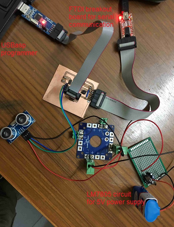
The first sensor that I used was an analog sensor i.e. ultrasonic sensor HC-SR04. Since this sensor had male header pins so it seemed best to connect it to the header pins of my echo board pcb made in week 7 with jumper wires. The below image shows the connections between the ultrasonic sensor and the header pins as well as with the ftdi breakout board.
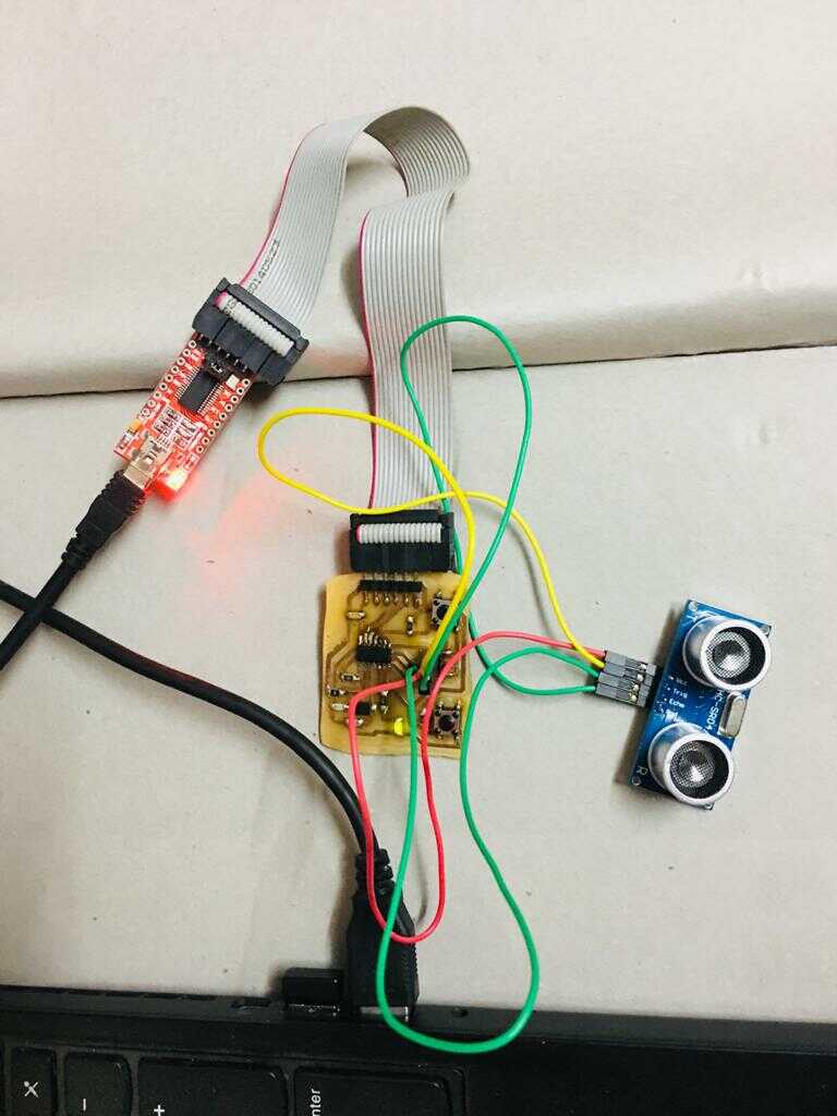
The attiny44 physical pin configuration corresponding to the digital pins of Arduino was as per the image below.
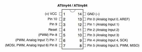
The echo and trigger pins were connected to arduino pins 5 and 6 which corresponded to physical pins 8 and 7 on the attiny44. The code was made to dim the led if the object was closeby and vice versa to demonstrate the working of the sensor.
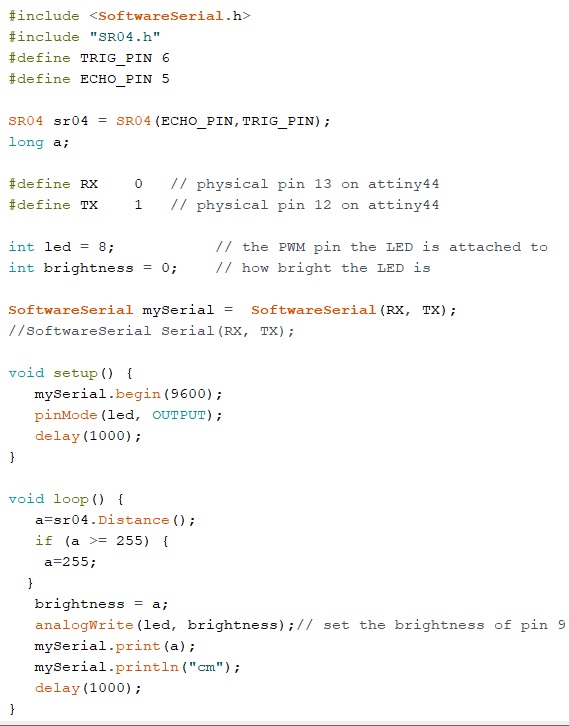
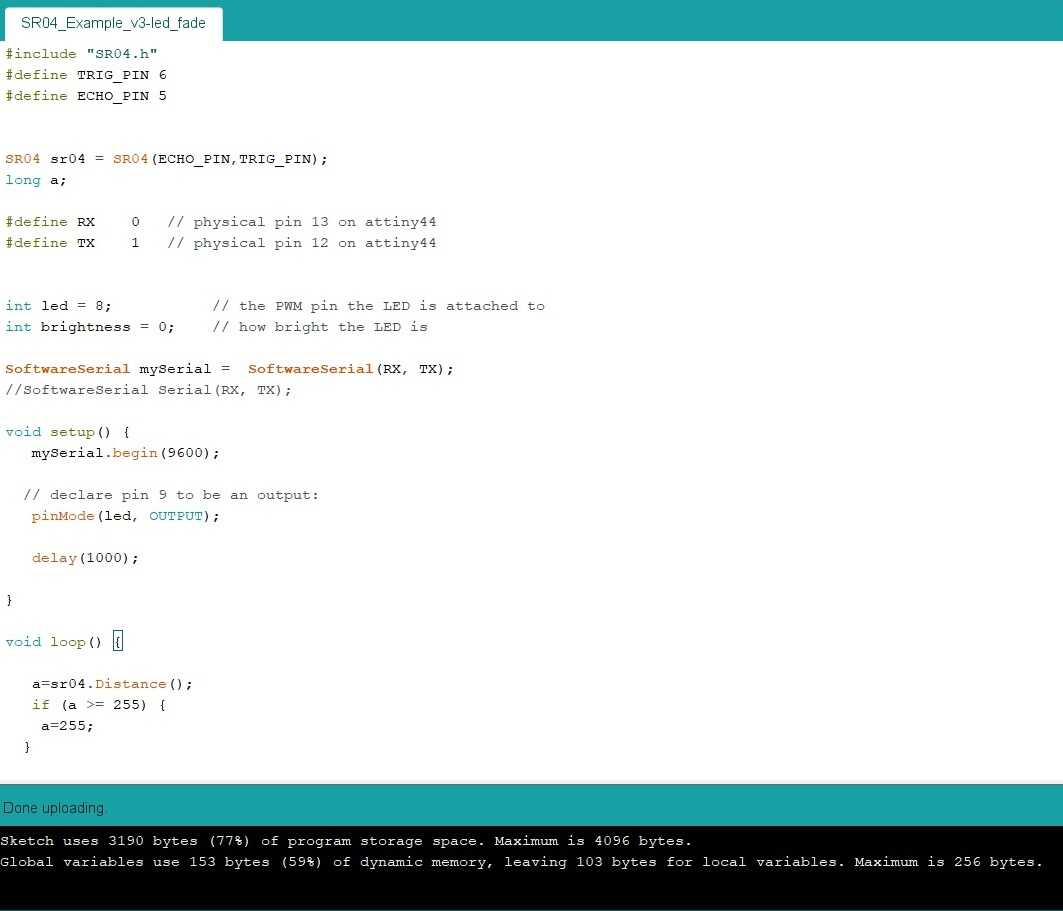
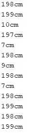
This sensor signal was observed on the arduino serial monitor corresponding to the above demo. When the view of the ultrasonic sensor was not obstructed it showed a reading of 198 cm and when a hand was brought close to it, the reading changed to 7 cm.
Another ATtiny44 board
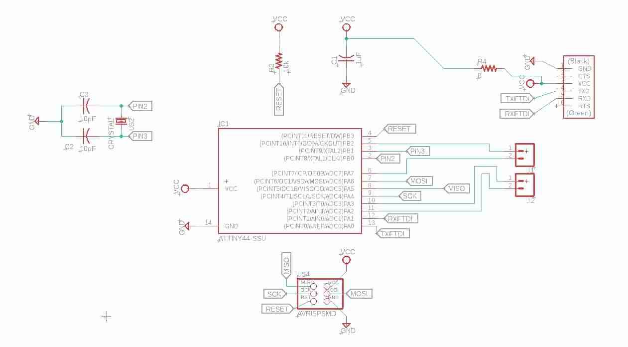
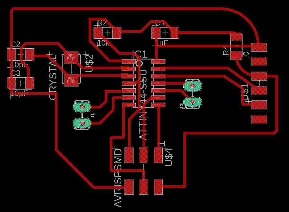
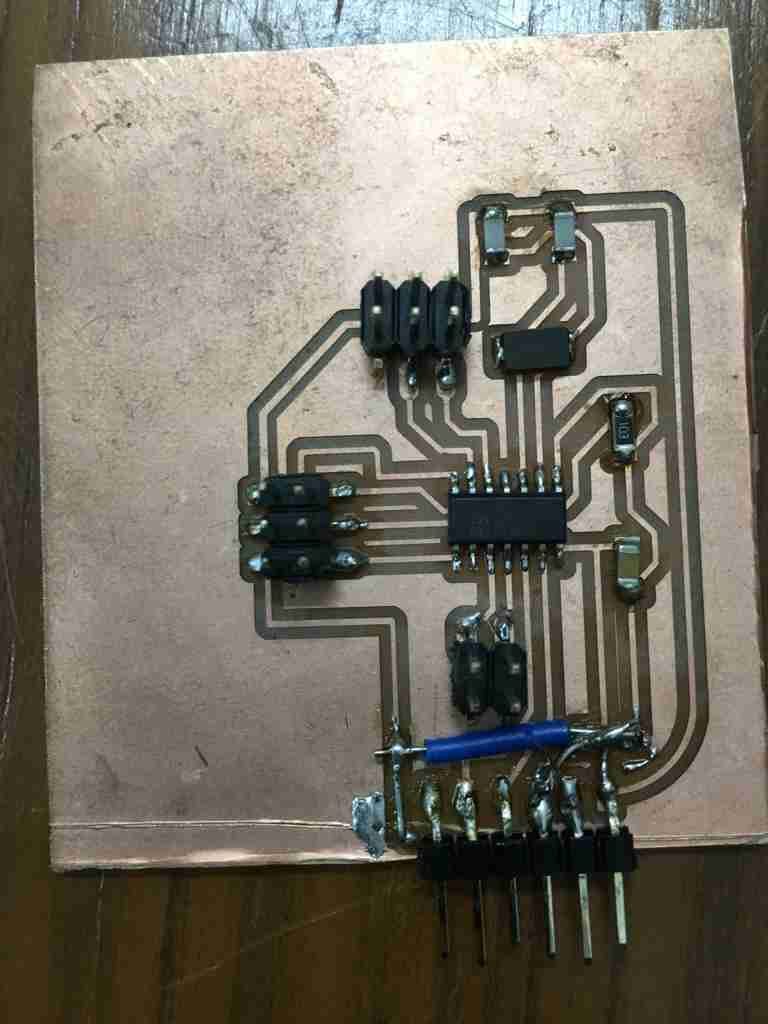
I made another board with ATtiny44 uC on it for my project and tested the ultrasonic sensor with it. These are the schematic, layout made in Eagle.
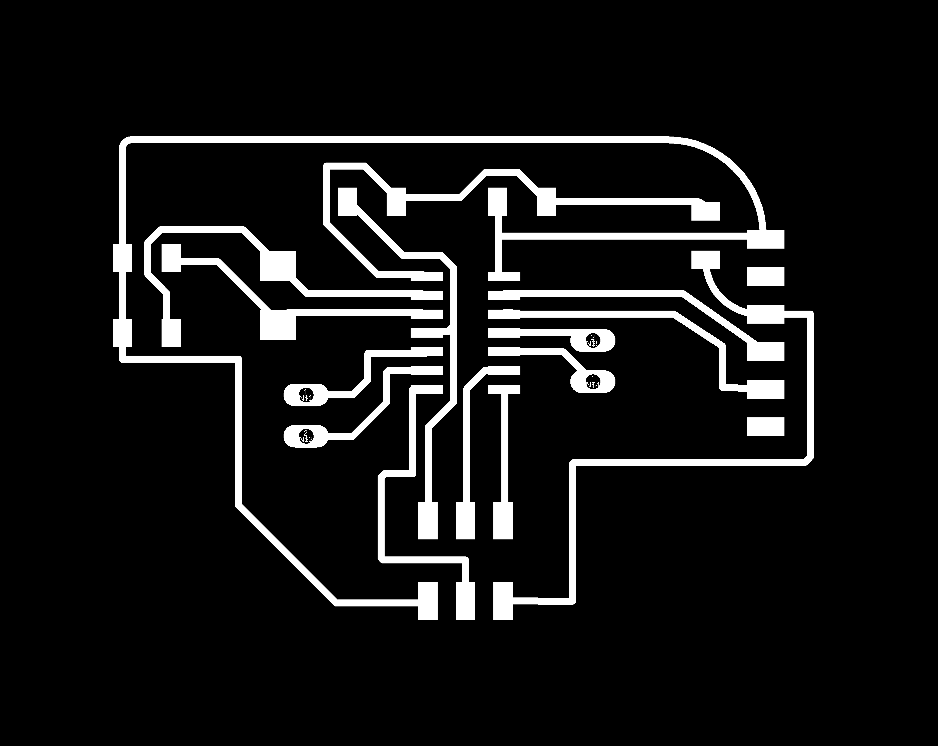
This is the png created in Eagle which was converted into rml with fab modules.

Here are the links for schematic, layout and png.
This is the board being milled on Roland SRM-20.
The board with the components soldered.
This image shows the connections.
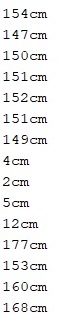
The video shows the demo of using the ultrasonic sensor. When hand is placed on the ultrasonic sensor, it shows lesser distance and vice versa.
This is the data on serial monitor corresponding to the above video.
Problems faced with PCB and fixes
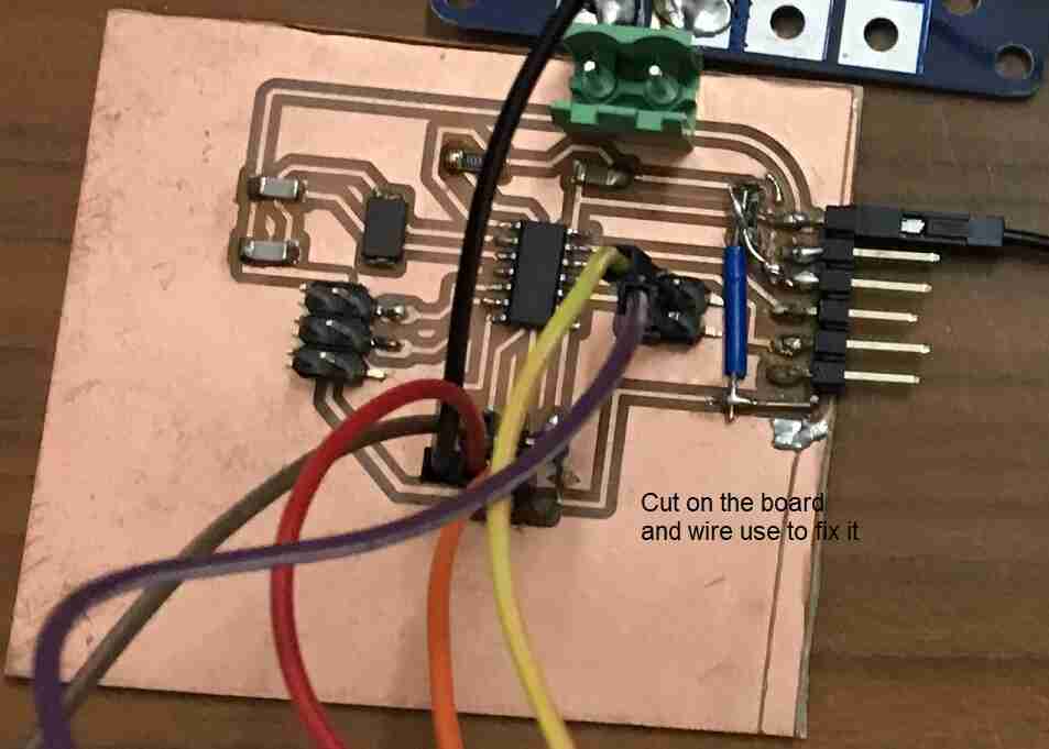
This image shows the problems faced while making this board and the fixes. I was trying to cut the board with a cutter due to shortage of time. The cut went inside one of the traces. I used jumper wires to fix this problem. I also used the uC datasheet to know the digital pins to use with sensor data and gave four extra header pins for this purpose.
PIR motion sensor
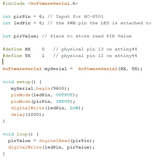
I used a PIR motion digital sensor which can instruct an LED to turn on if motion is detected.
This code was written in arduino and was uploaded using the USBasp ISP.
The PIR sensor was connected to the echo board with jumper cables.
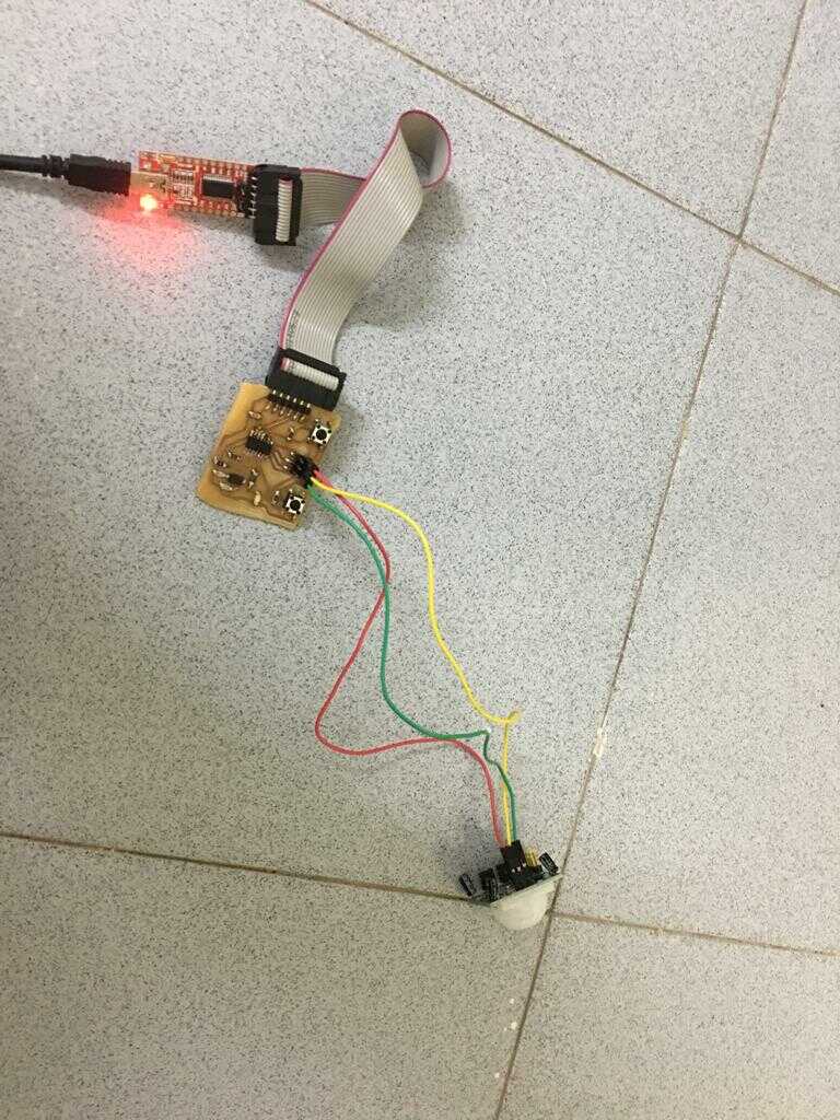
This video shows the operation of PIR sensor for motion detection. Whenever the hand comes in front of the PIR sensor, the LED blinks otherwise the LED is off.
Input devices for the project
I also wanted to share the link to the input devices that I have used in my project. This link shows the input devices i.e. throttle, left and right brakes and ignition switch attached to ATtiny44. This whole section shows how the input devices and the output devices work together. I have also written my own code for this section to make the 24 V loads i.e. DC motor and LED strip work with the input devices.
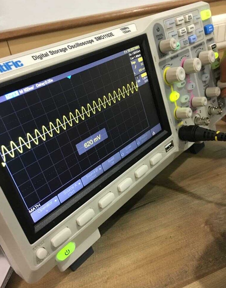
DSO to measure digital and analog signals
Our local instructor Rahul gave us a demo of how to use DSO. He connected the probes to the crystal of Ardunio Uno which showed a frequency of 16 MHz.
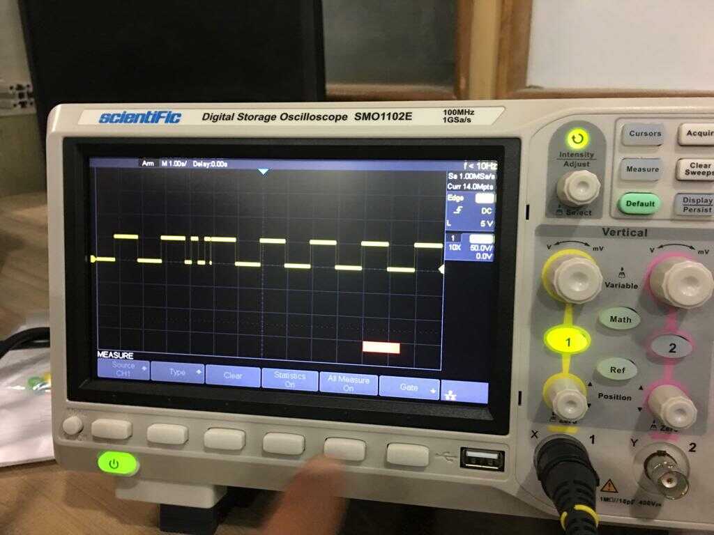
He also ran the LED blink program in Ardunio Uno and we observed the pulse signal on DSO.

Solar powered electric bike con kit by Jay Dhariwal is licensed under a Creative Commons Attribution 4.0 International License