8. Making something big (Mar 13)
This week we were suggested to test runout, alignment, speeds, feeds and toolpaths for our machine for the group assignment. For the individual assignment, we had to make something big.
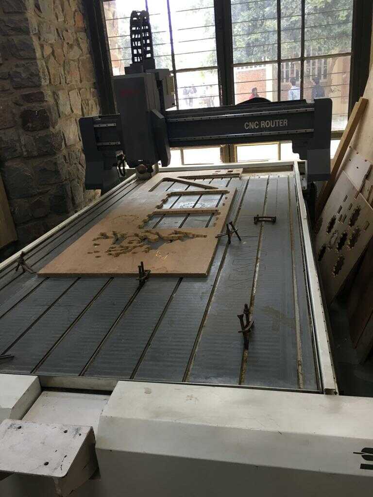
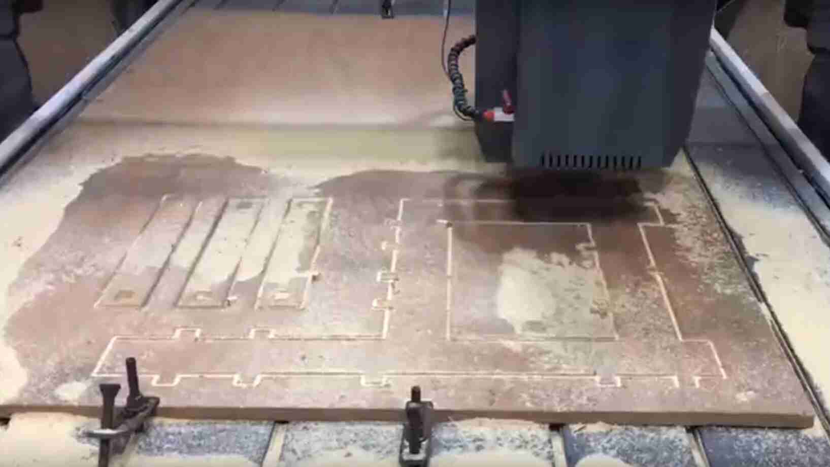
CNC router description
This was the SIL-1325 CNC Router that we had with a bed size of 8X4 feet. This was my first glimpse of this huge router. This image also shows the clamps that have to be used to hold the work piece. It is important to distribute the clamps uniformly to the entire work piece to make sure that the work piece doesn’t lift up from anywhere.
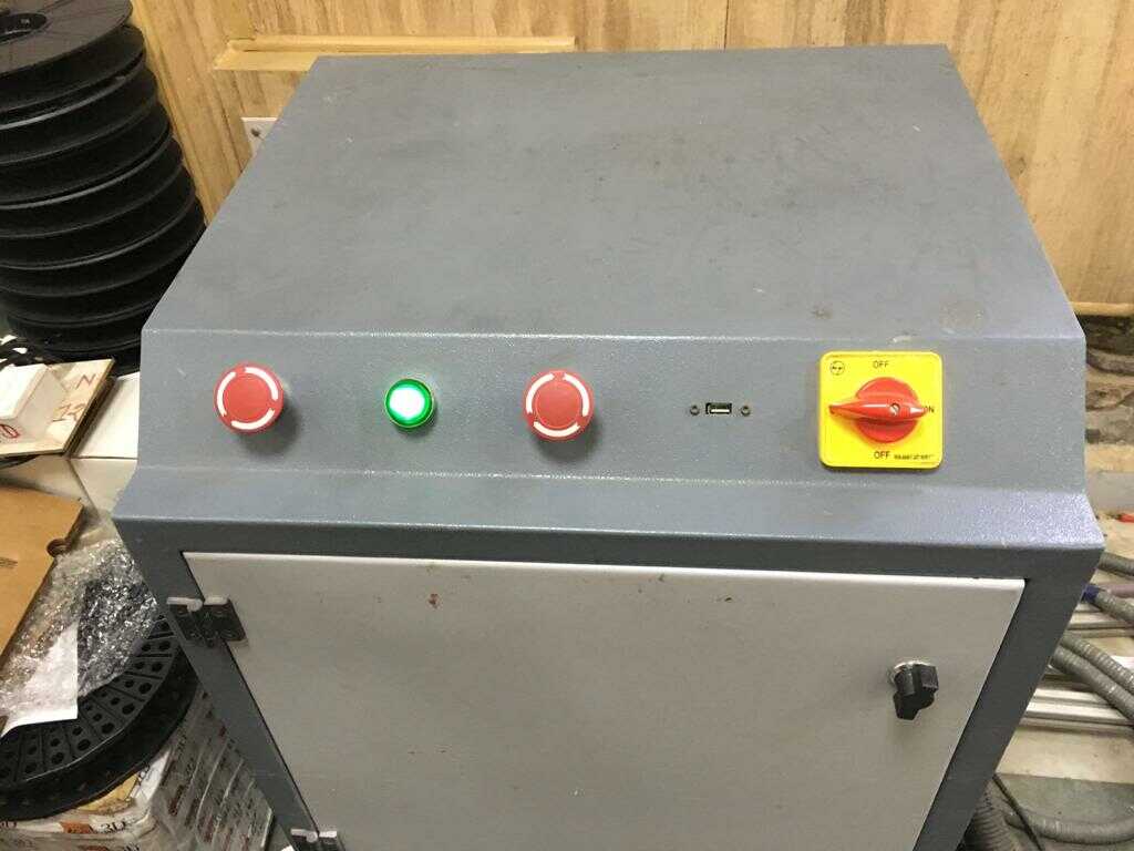
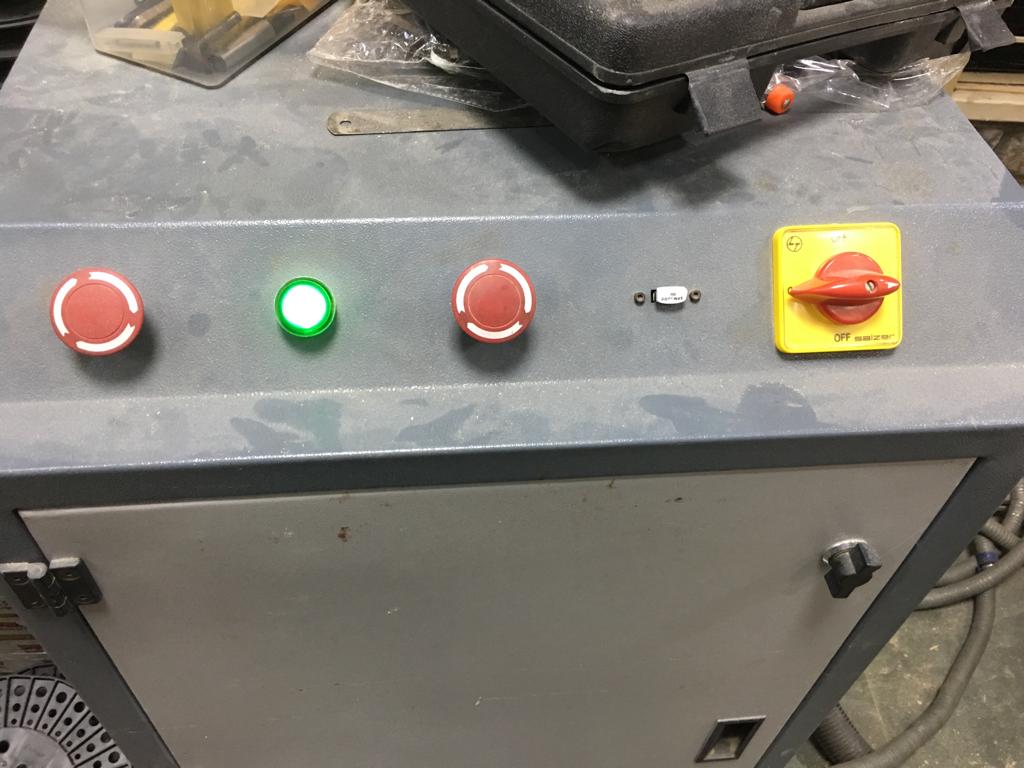
CNC router controls
The front controls are shown here. The left most emergency switch is to turn the spindle off. The rightmost switch is to turn the machine on. The middle emergency switch is to stop the machine altogether and this is the one we need to press in case of emergency. The switch lighted up green is to turn the machine on.
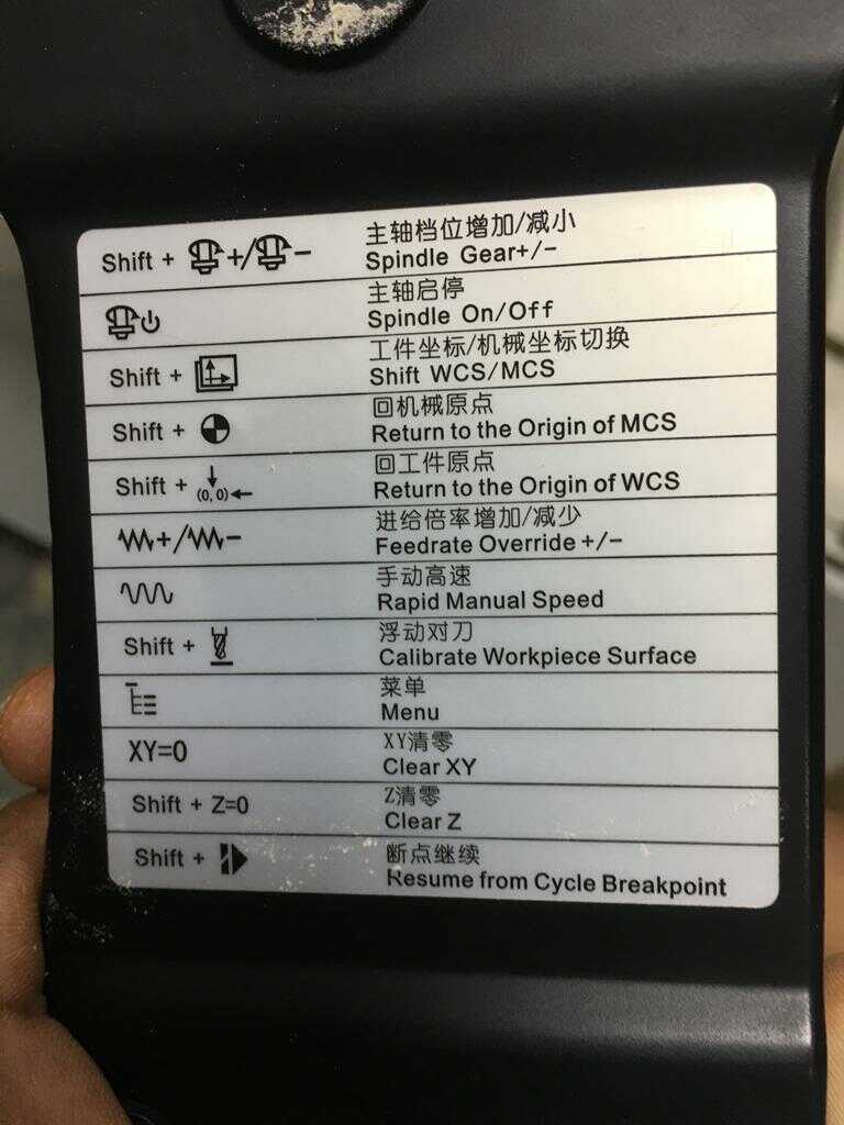
The cnc router is controlled using this teaching pendant.
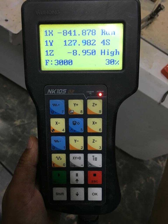
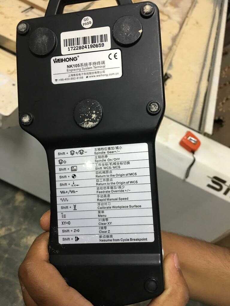
Some of the not so obvious commands are listed here. For instance, we can change the spindle speed and feed rate using the commands given.
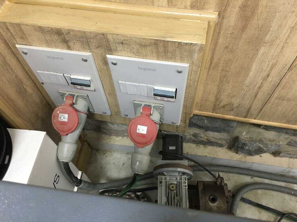
These circuit breakers need to be turned on to start the vacuum pump.
Fixing the material
The material is fixed with these clamps. We used plier and spanner to tighten these clamps over the plywood board. The screw goes in the rails. We divide the clamps uniformly on the plywood board to secure the board in place.
Homing the machine
We press Shift and 4 together to bring the cnc router to machine’s home position. It is important to home the machine first through which the machine knows its reference points. It helps to first manually bring the tool close to the bottom left corner with the X and Y keys. Please keep the jog option selected for faster operation.
Setting the origin
Next we have to set our own origin for the work piece. The origin is set on the bottom right corner as the reference. We set the button “XY=0” to set the origin for X and Y.
Next we have to calibrate Z axis. We bring the Z axis disc below the cnc bit and press Shift and 0 together for surfacing. After surfacing, we need to press “Z=0” to set up our Z position. I have borrowed this video from our local instructor, Rahul’s webpage since I didn’t remember to take a video of this operation.
Loading the file
To load the menu, we press the question mark symbol. The cnc extension files can be loaded on a USB drive and loaded in this slot. To cut the work piece, we just press play.
Group work
I had done the tests on the laser cutter in a lot of detail so I had a hang of how to do the tests in the group work of the CNC router. But I couldn’t be involved in these tests for reasons mentioned at the very end of this assignment. I am describing my understanding of the tests which were done by the previous batch of 2018 and what I understand from them. Our group’s work can be found on our lab’s page.
Cutting Speed
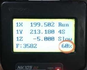
Cutting speed is defined as the speed of the tool (usually denoted in feet/min) when it is cutting the workpiece. The cutting speed is mentioned in % on the teach pendant from 10% to 100%. The instructor suggested not to go beyond 70% for safety reasons.
Feed rate and spindle rpm
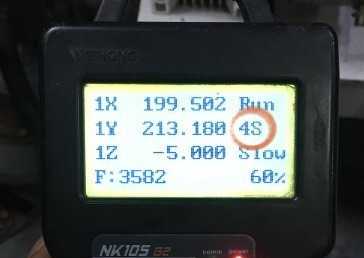
Feed rate and spindle rpm are related. Feed rate is the distance travelled in one revolution of the spindle. The spindle speed is denoted by a number followed by S with 4S being the slowest and 7S being the fastest. The maximum spindle speed at 100% is 3200 rpm.
The vector of cutting speed is perpendicular to the vector of feed.
Testing runout
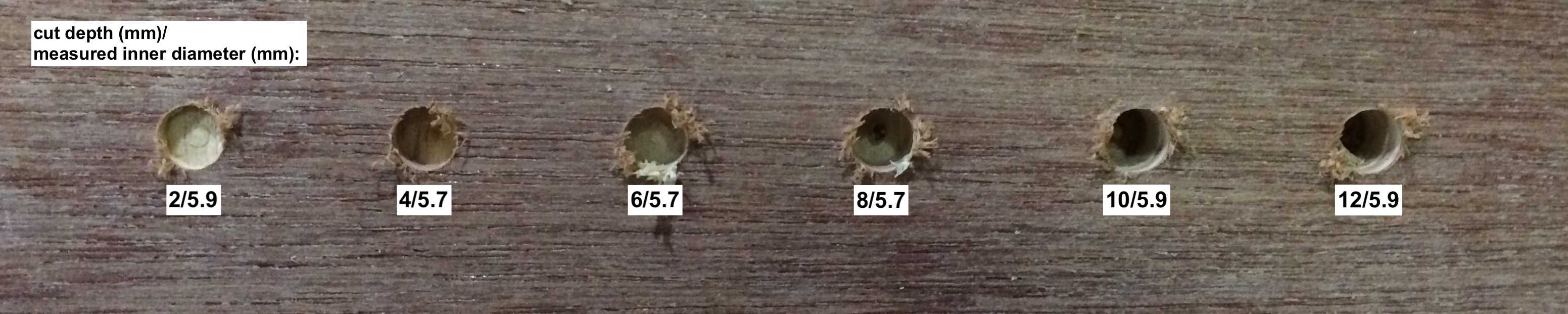
The end mill has some degrees of freedom in the collet, so it may wobble a bit, so the runout is the actual diameter of what is cut. To test runout, holes are cut at different depths and inner diameters are measured. The data shows that the diameter of the hole is not affected by the depth of cut much.
Testing tool path
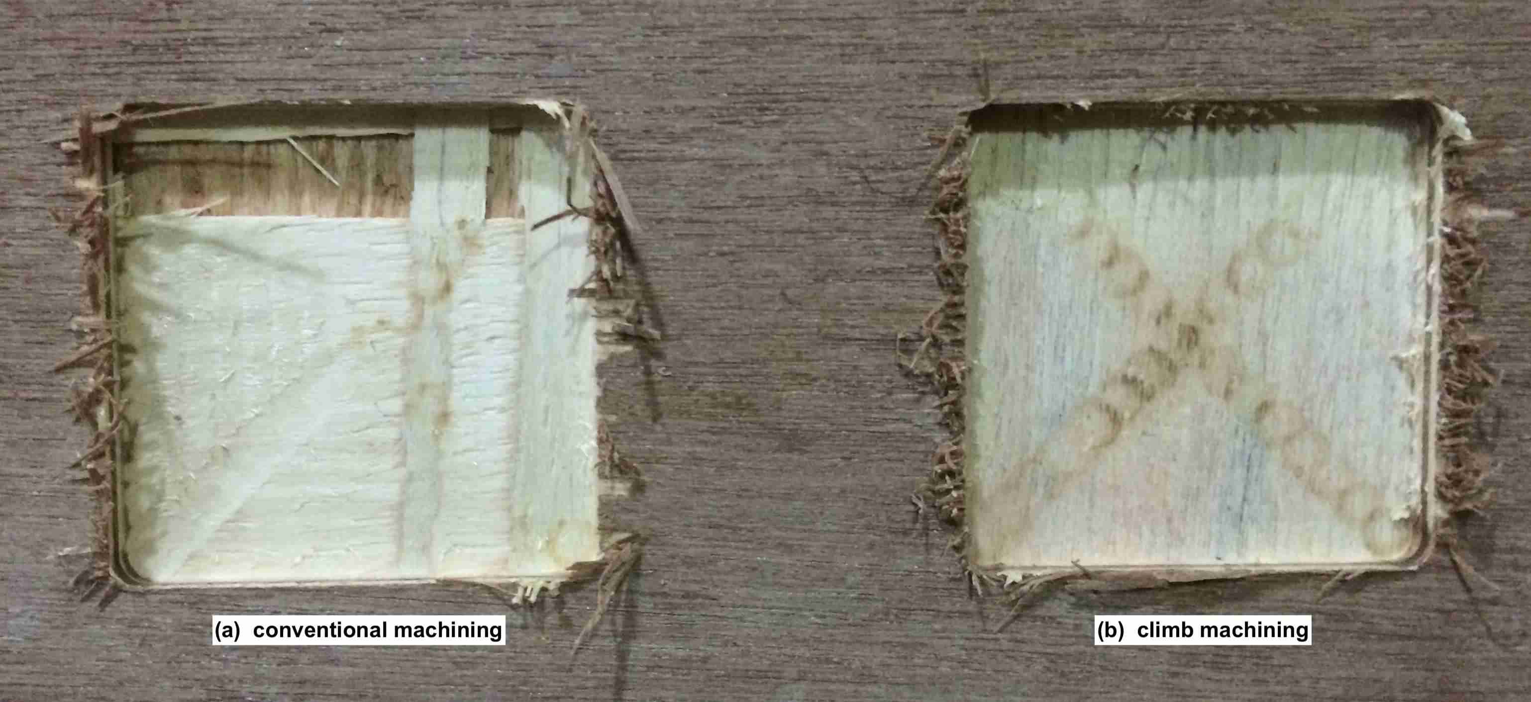
We can have cutting as either conventional or climb milling.
In conventional milling, the cutter rotates against the feed.
In climb milling, the cutter rotates with the feed.
Climb milling causes less load on the tool thus increasing its life. It also leads to better surface finish. Conventional milling may be suggested when the part is case hardened and greater force may be required in the beginning of the tool workpiece interaction.
Testing alignment
The alignment of the machine can be tested by cutting a square part and see if the tool cuts the square at right angles. It is possible that some of the not so good quality machines may drift over time resulting in alignment issues.
Inspiration
I wanted to make something useful for this week. I have really liked the possibility of using pressfit construction for furniture making that we had explored during the laser cutting week. I wanted to extend this work to make a bench for this week.
I got some idea about interlocking bench making from an instructable.
I also searched for chairs in google images.
I also looked for standard sizes of office chairs. I used a size of 18 inches for chair width, depth, floor height, backrest height, etc.
Scaled prototype
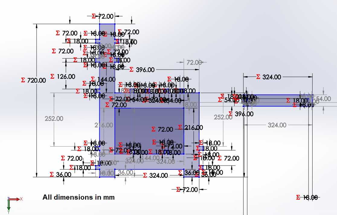
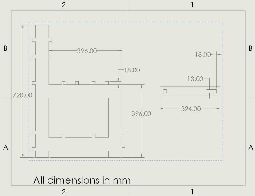
CAD model
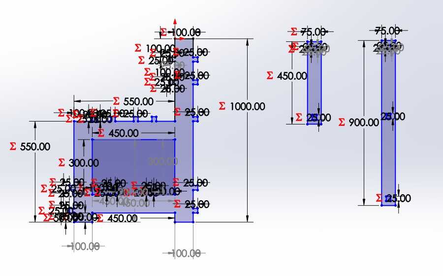
I made a parametric design in Solidworks for a chair and a bench which can seat two people.
Kerf calculation
I wanted to use acrylic for the scaled prototype making. I hadn’t used it during the laser cutting week so I needed to calculate the kerf to find out the difference between the CAD dimensions and the actual output.
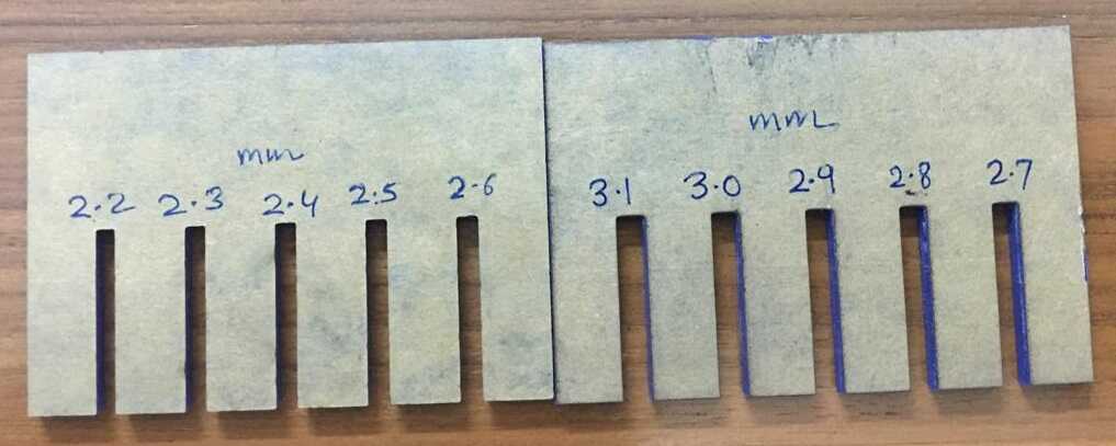
I found out the thickness of the acrylic sheet to be 2.9 mm from a digital caliper.
I drew the kerf comb from 2.2 to 3.1 mm to find out the kerf.
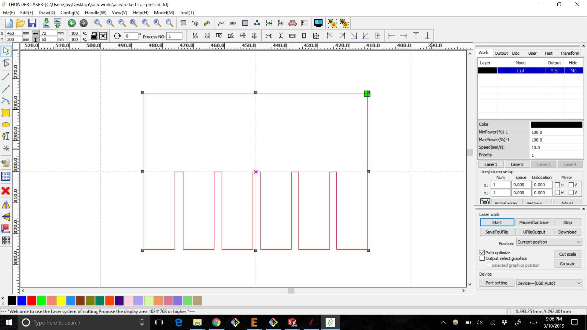
I found out that a CAD slot thickness of 2.5 mm fit the sheet the best so it was used for the hole width.
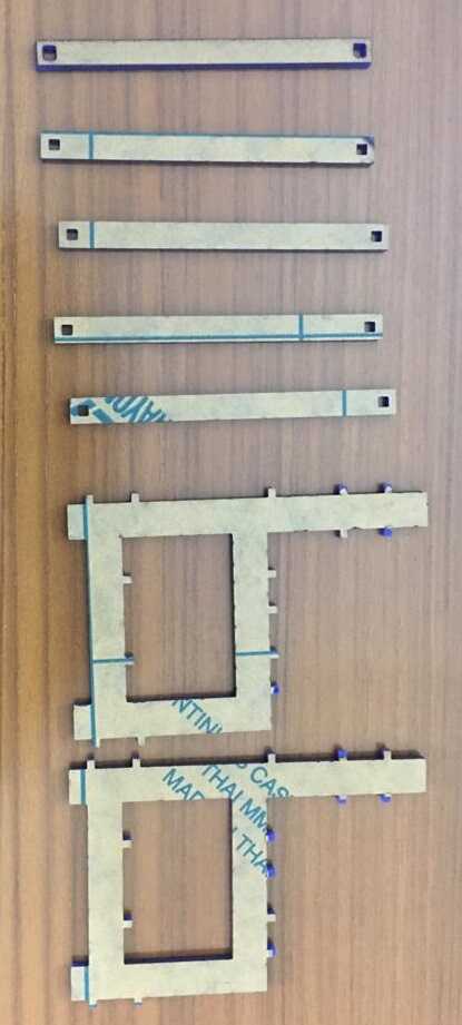
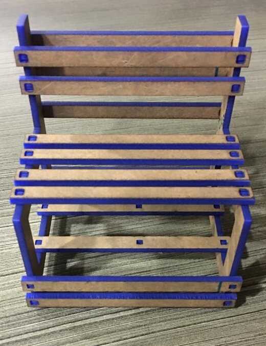
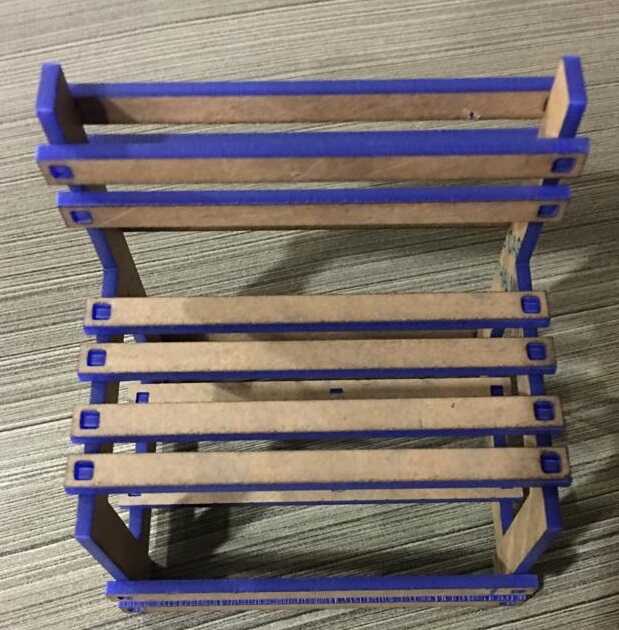
Scaled prototype images
These are the images of the parts cut using the laser cutter.
These are the images after assembly. The neat thing about this design is how simple it is to make, portability and how it can be extended to create benches to seat more people.
Make something big
After fine tuning the design for the scaled prototype, it was time to make something big for which I was very excited.
CAD model
We had plywood provided to us by the lab for making something big. I measured the plywood sheet thickness to be 18 mm. I changed the slot thickness in my parametric CAD model and changed the other dimensions accordingly. The changed dimensions reduced the size of my chair from 18 inches to 13 inches which may be suited as a kid’s chair.
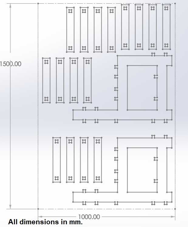
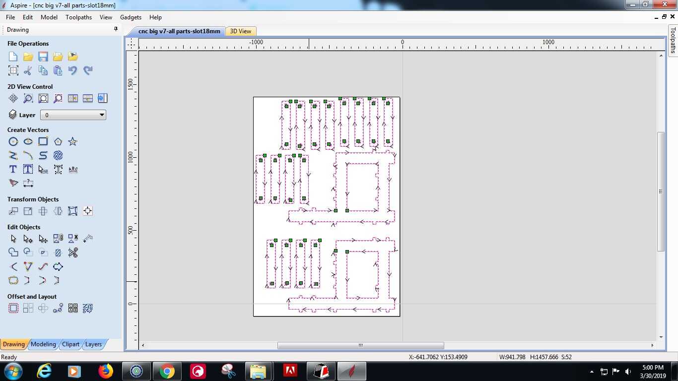
The dimensions of the plywood sheet were 1100 mm by 1600 mm. Since we needed to keep about 100 mm for the clamps, so I decided to fit in all the parts I would need to cut in a rectangle of 1000 mm by 1500 mm and cut everything at one time. I created a dxf file and it was time to create the tool path using Aspire software.
Aspire software for CNC milling
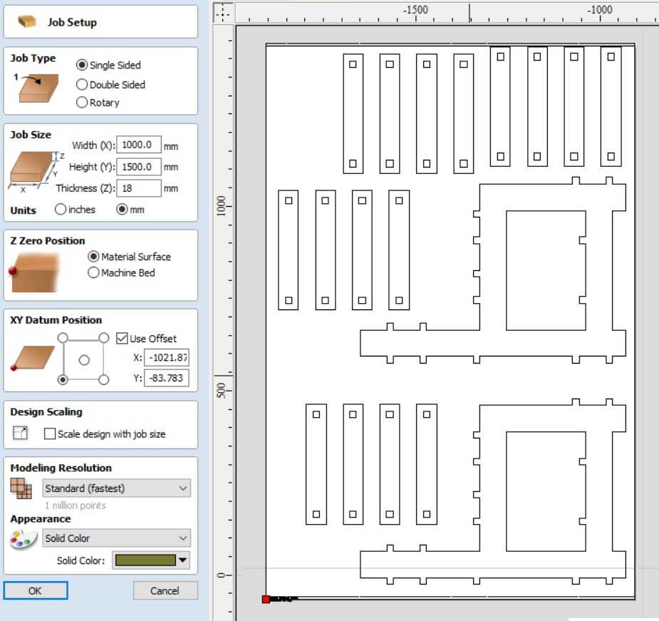
I watched a video tutorial that came with the Aspire software. Following the advice in the video tutorial, the dxf file needs to be imported in Aspire. The width and height have been kept as per the plywood sheet dimensions. Scale design with job size can be clicked and unclicked to get the design in centre.
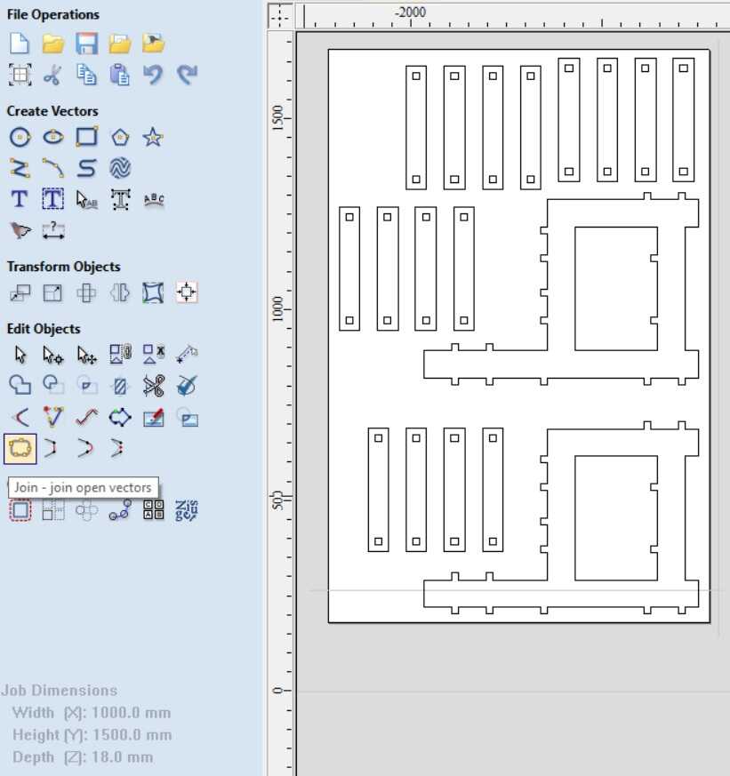
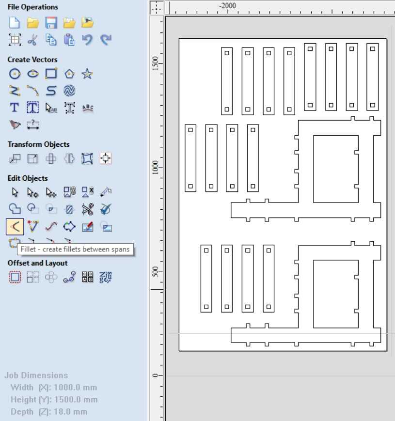
We need to join the open vectors next. Click on the hover text icon.
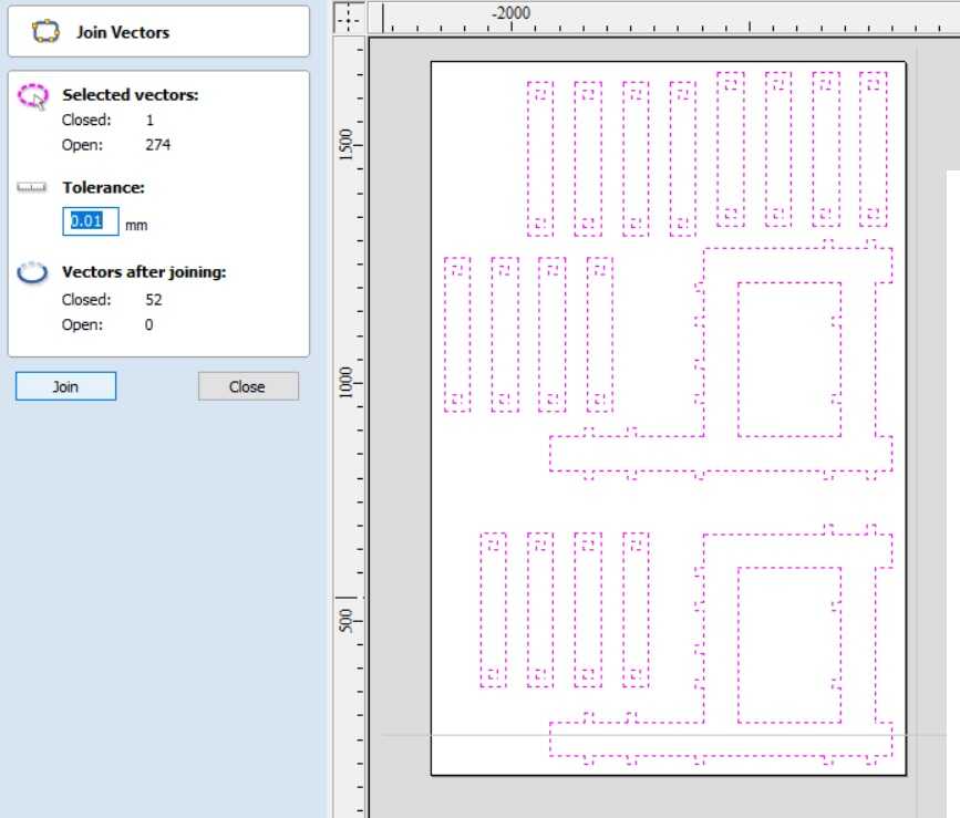
Select the entire design and click on join to join open vectors. The result is all the vectors are closed.
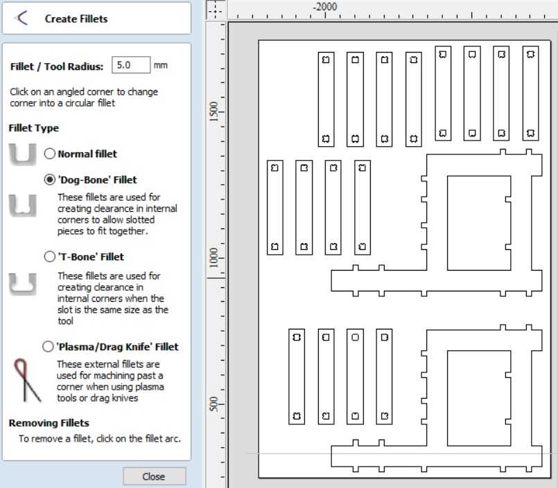
Next, we need to create dog bone fillet in the female slots for ease of slotting.
The fillet size is kept to be 6 mm as per the end mill bit size of 6 mm.
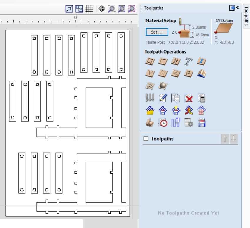
Next, we need to create the tool path.
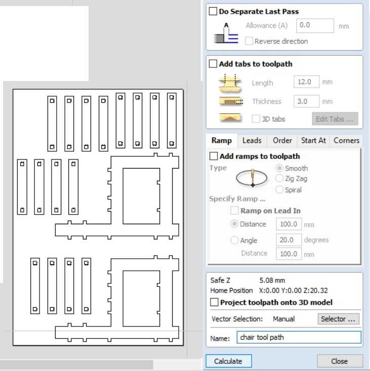
In the profile settings for the tool path, we need to select the end mill bit diameter to be 6 mm. The number of passes to be 6. The spindle rpm, feed rate and plunge rate are as given in the image. The bit needs to traverse outside of the line so that our dimensions are intact. The aspire software automatically makes the slots to be inside.
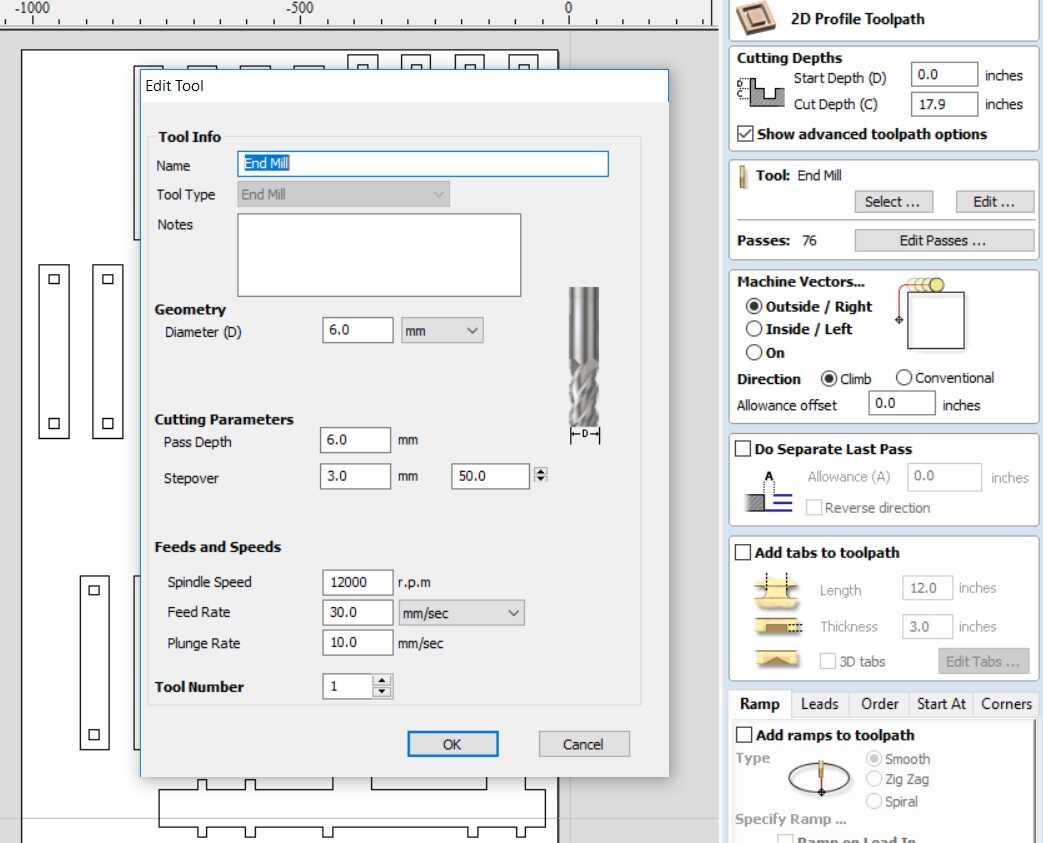
Tabs can be added to make sure that the cut holes don’t come out of the work piece. Tab length can be 12 mm and its thickness can be 2mm.
Now click on calculate to calculate the tool path.
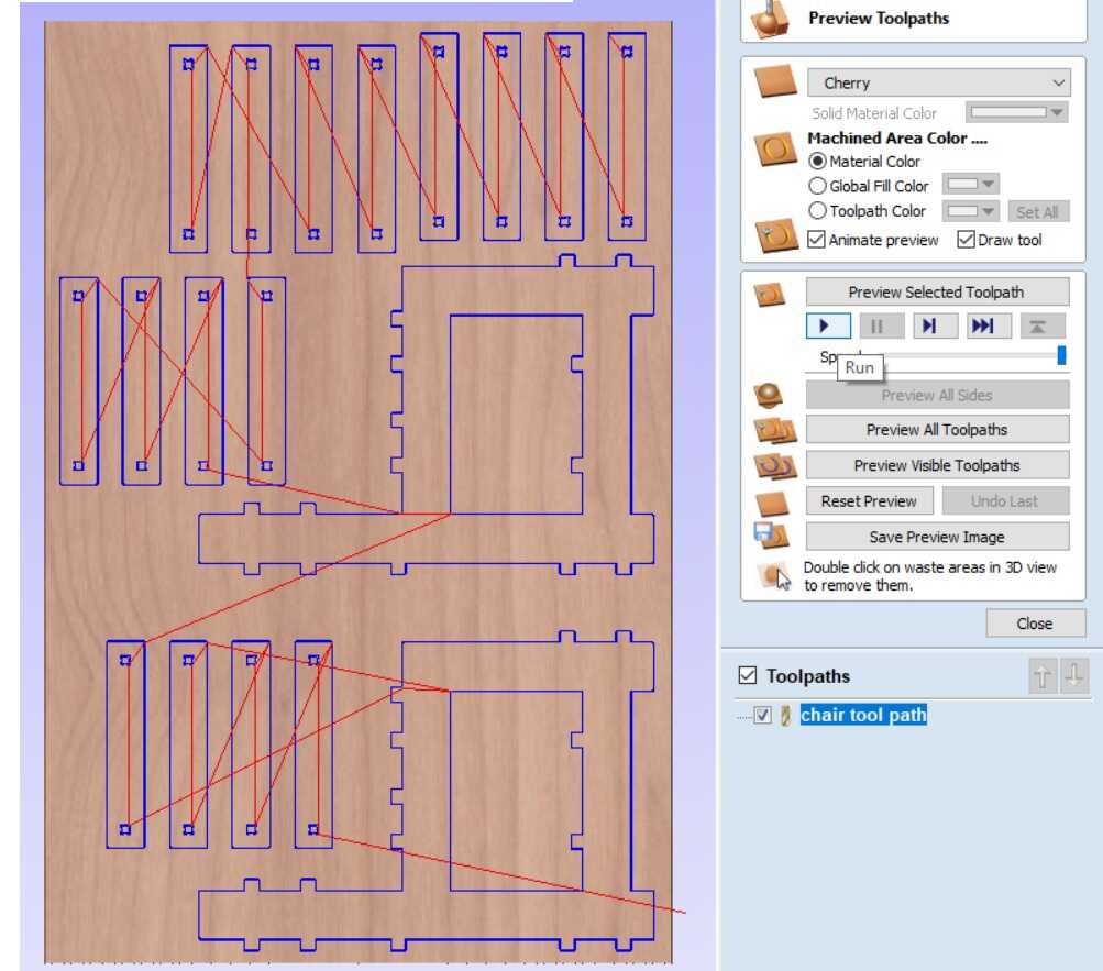
The tool path can be previewed to make sure that it is as expected.
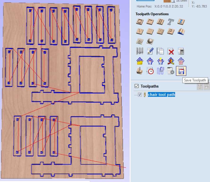
The tool path needs to be saved with the appropriate name to create a cnc file.
The tool path can be checked for outside for the outer boundaries and inside for the inner boundaries.
CNC milling action
CNC router in action
The below video shows CNC router milling operation towards the beginning.
The below video shows CNC router milling operation towards the end.
chair shots
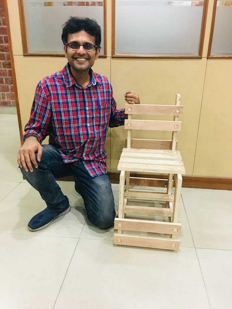
The chair was assembled with the cut pieces.
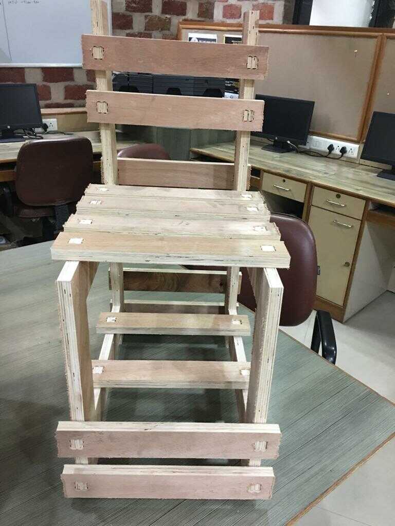
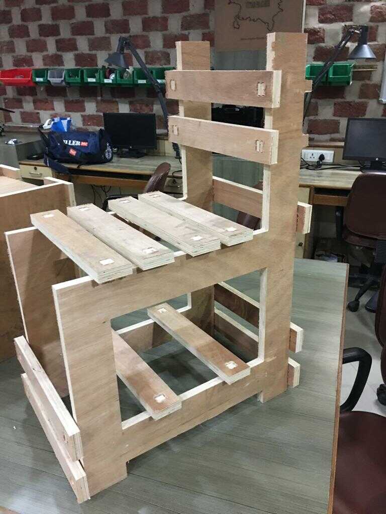
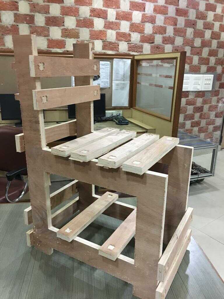
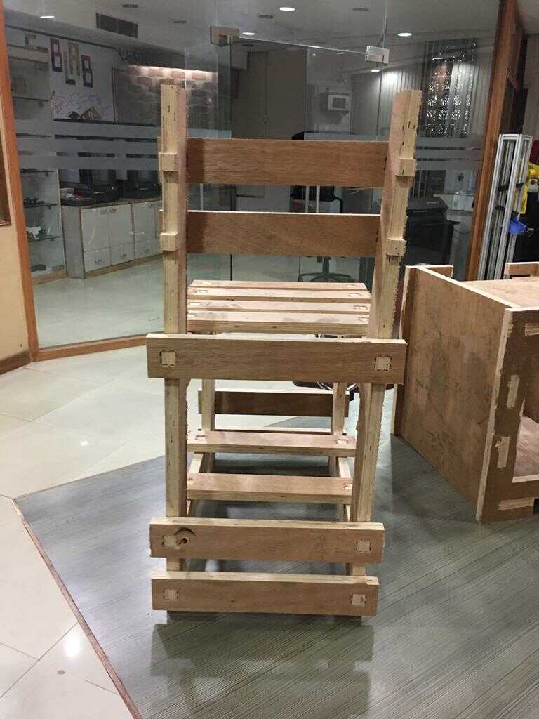
hero shots
I was so happy with the finished work piece.


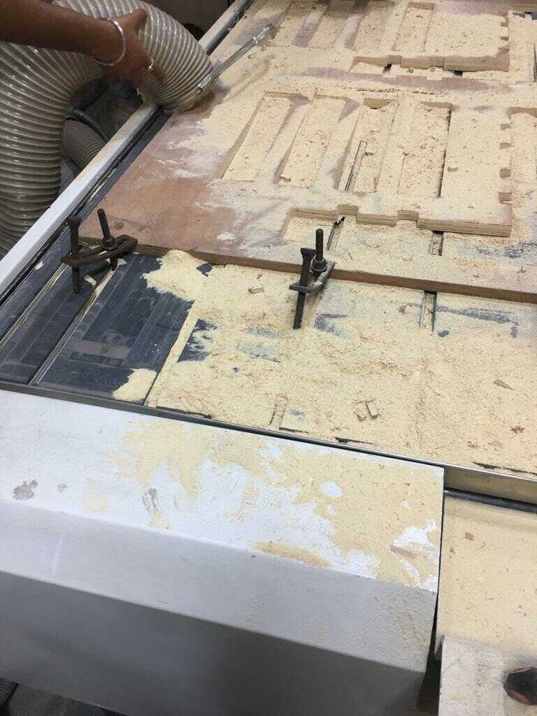
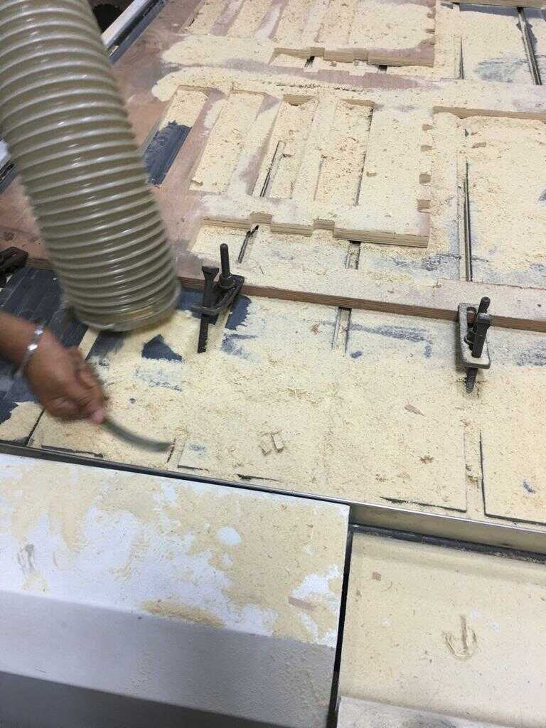
cleaning up
These are the images of the clean up with the suction hose.
lessons learnt
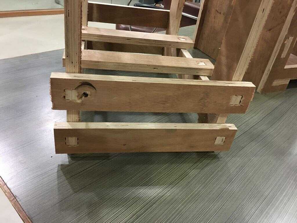
I hadn’t put tabs in my work piece so one of the parts got raised up by the CNC router bit and cut another hole in it as shown in the image below. I had to stop the CNC router at this point. But this was one of the last pieces to be milled so I didn’t have to setup another plywood.
I was definitely happy with the output. I had worked on it with our local instrcutor Rahul who was good with the machine, which led to a lot of learning.
The fit was could have been tighter. I missed out on the group work to determine the exact runout for my thickness of the plywood. This may have helped with having a tighter fit. The missing out of group work was partly to do with the machine being down during the assignment week and for some time later and it had also to do with myself only being able to work in the lab on Saturdays during those days as I am a working professional and the lab wasn’t open on Sundays around those times. So, I had to go ahead with my individual assignment without the runout calculation.
On another note, I also found the making of dog bone fillet for ease of slotting to be useful.
This was a very exciting week. I was the Project Engineer of the team which had built something really big earlier. It was building a complete prefabricated house in France as a part of Solar Decathlon Europe team from India in 2014. I am looking forward to the learnings here to build more low cost houses in the Indian context which is badly needed for the poor here.
Design files
Download for the parametric CAD model in Solidworks for the chair.
Download for the parts of the chair to be cut on the cnc router imported in Aspire software.
Download for the cnc code of the tool path for the parts of the chair to be cut on the cnc router.

Solar powered electric bike con kit by Jay Dhariwal is licensed under a Creative Commons Attribution 4.0 International License