12. Output Devices (Apr 10)
This week we were suggested to measure the power consumption of an output device for the group assignment. For the individual assignment, we had to add an output device to a microcontroller board we had designed and we had to program it to do something.
Output devices
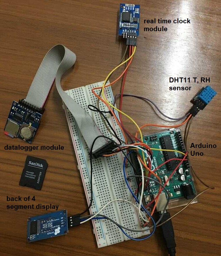
I wanted to add a datalogger with an SD card as an output device to read the data from a temperature, humidity sensor. For the timestamp, I used an RTC clock. I also wanted to add a 4 segment display to read the output. I planned to interface it with Arduino Uno board first and then with my own board based on Satshakit.
Output devices interfaced with Arduino Uno
datalogger module
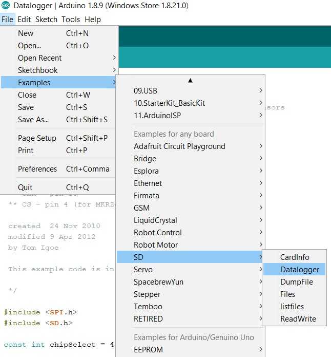
I bought a datalogger module with SD card slot in it. I also bought a micro SDHC card with an adapter. I next interfaced the datalogger with Arduino Uno using the inbuilt datalogger example.
temp and RH sensor
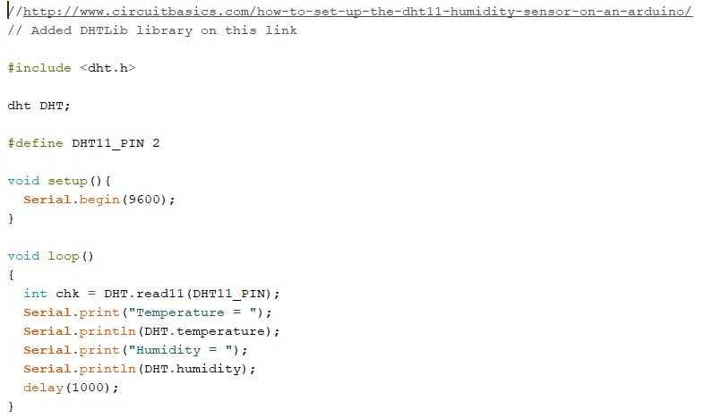
I had a DHT11 3 pin temperature and humidity sensor for which I found a library and a corresponding simple code for Arduino IDE.
real time clock module
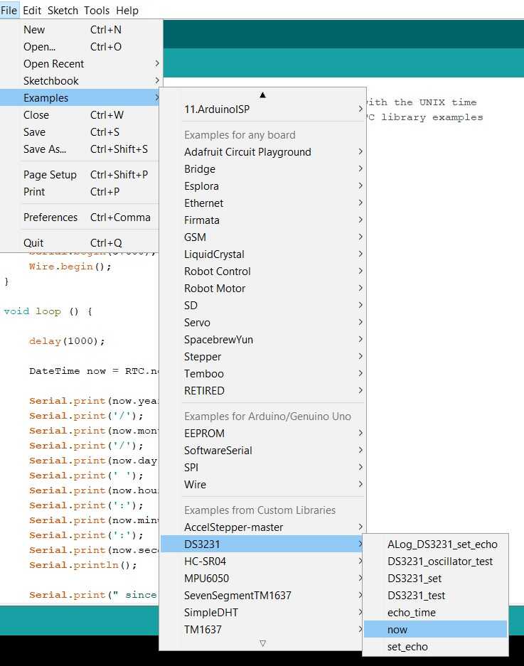
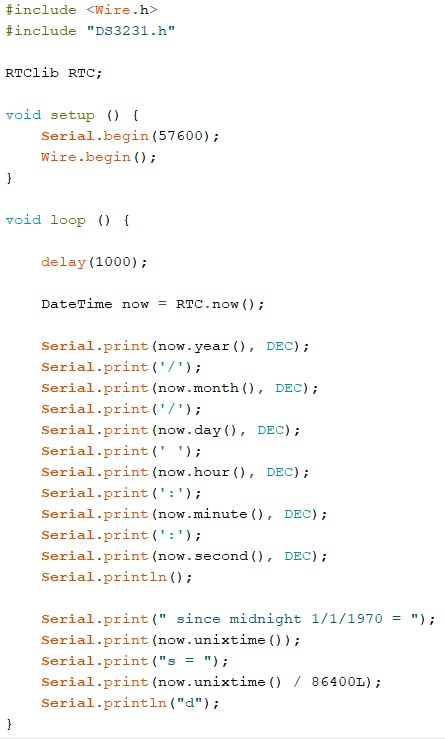
For the timestamp, I had to add a real time clock. I had a DS3231 RTC real time clock memory module based I2C communication. I got the library for this module and the corresponding arduino code.
4 segment display
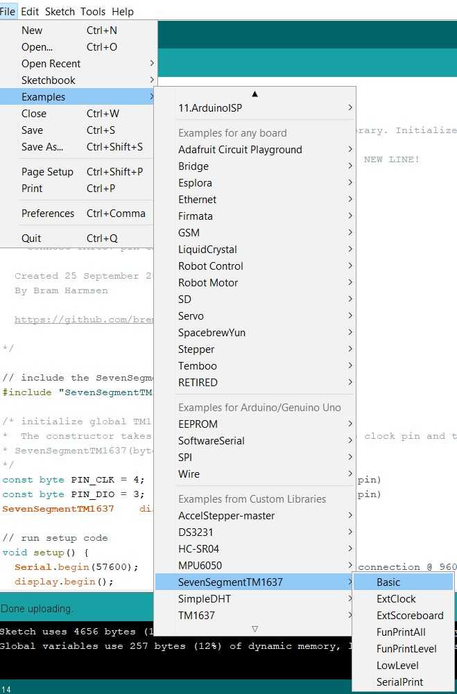
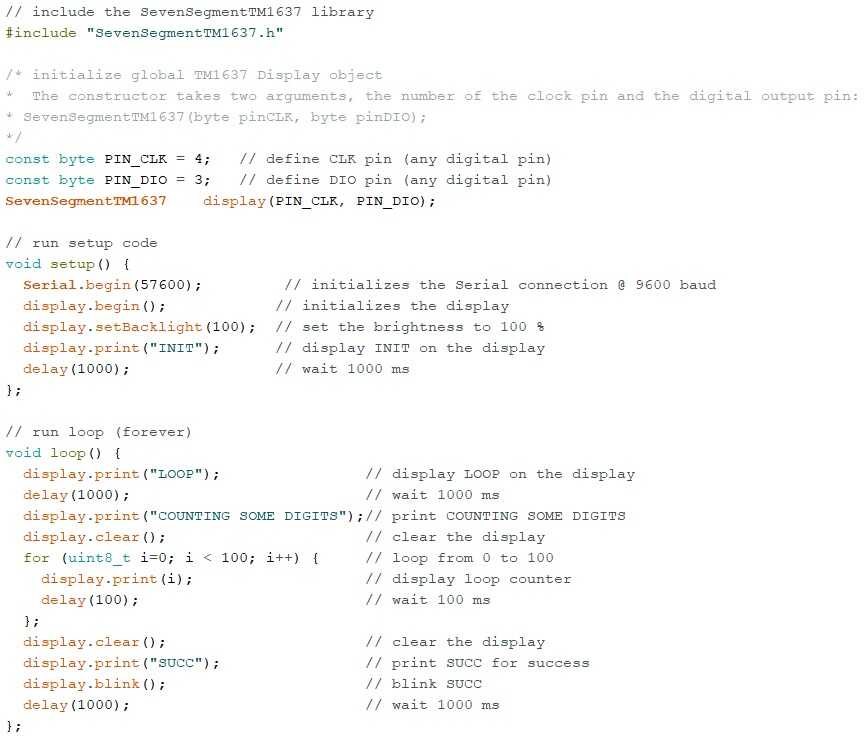
I received TM1637 display from our lab for which I used this library as per this advice.
bringing everything together
I put all these pieces of code and components together. This image shows how the components were connected together.
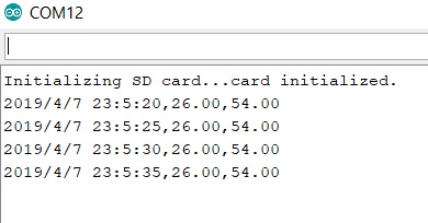
This video shows the working of this setup. The display shows the temperature in degrees celsius and the RH in %.
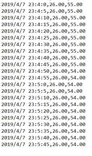
This image shows the serial output.
This image shows the data being stored in the sd card.
Input and Output devices for my project
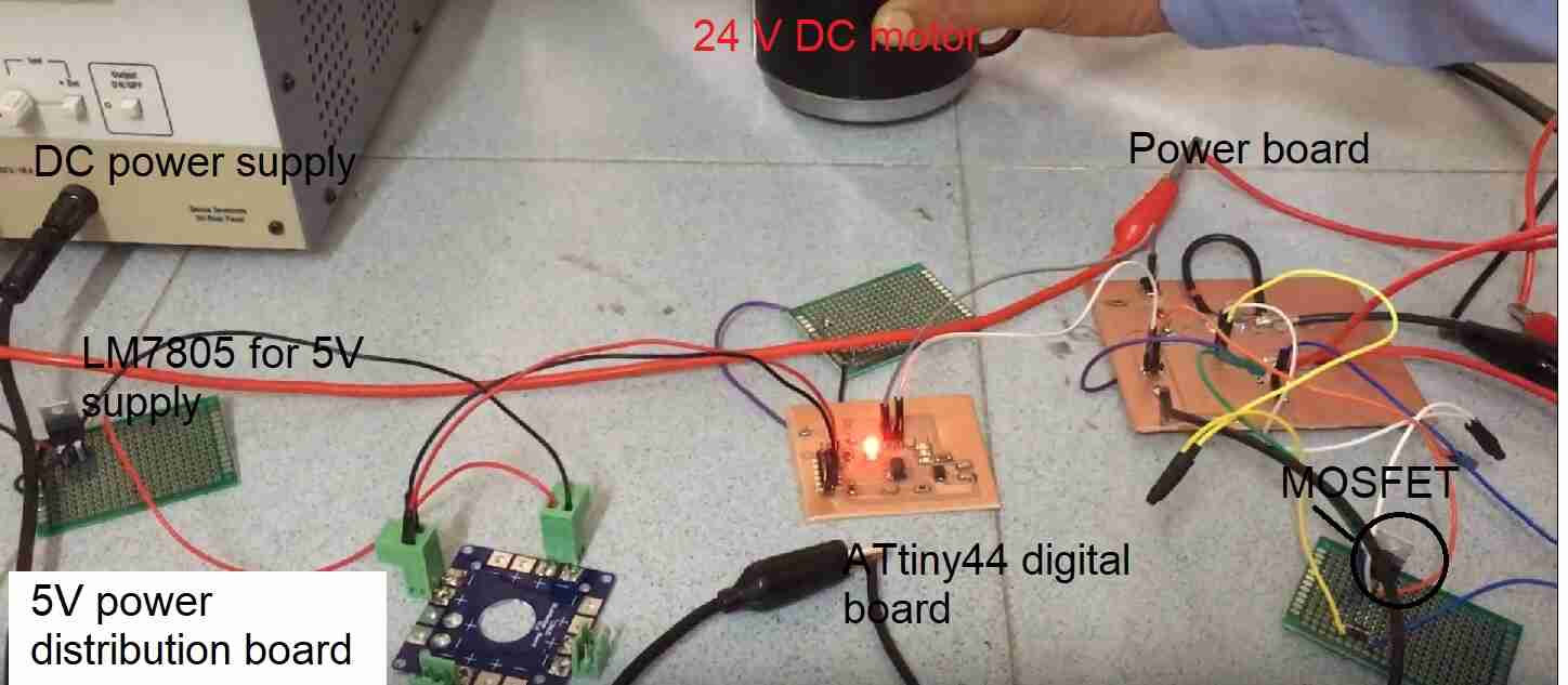
I wanted to power a 24 V DC motor and 24 V LED strip to be used as headlight for my project. I used PWM using IRLZ44N MOSFET and ATtiny44 uC to power these loads. I kept the digital and power boards separate.
PWM motor control with N channel Mosfet
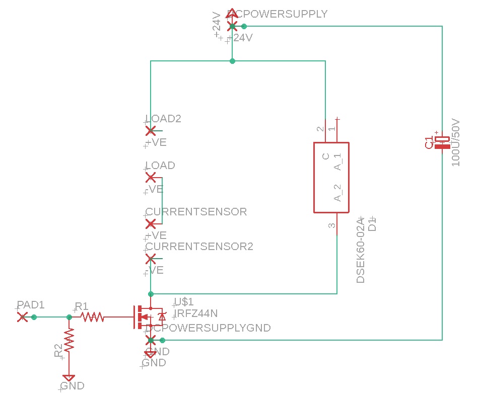
The 24 V PMDC motor and the 24 V LED strip can be controlled using the PWM signal from the uC. The PWM channel can be amplified using an N channel Mosfet.
I got the schematic of this circuit from this link and then modified it for my needs.
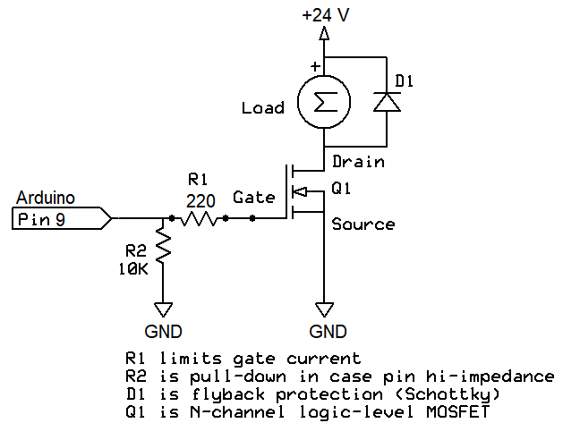
The MOSFET used was IRLZ44N
The Schottky diode used was IN5819.
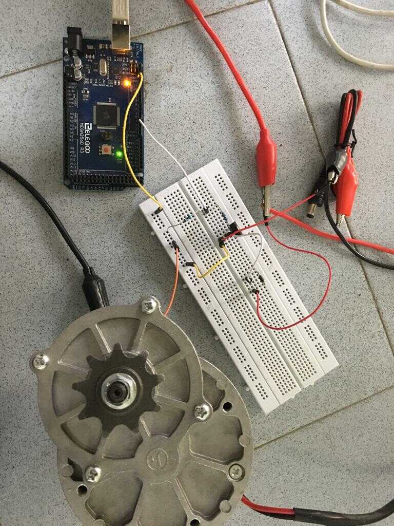
The circuit was implemented on the breadboard using an Arduino Mega 2560.
The fade LED code was used to increase and decrease the speed of the motor with PWM signals.
/*
  Fade

  This example shows how to fade an LED on pin 9 using the analogWrite()
  function.

  The analogWrite() function uses PWM, so if you want to change the pin you're
  using, be sure to use another PWM capable pin. On most Arduino, the PWM pins
  are identified with a "~" sign, like ~3, ~5, ~6, ~9, ~10 and ~11.

  This example code is in the public domain.

  http://www.arduino.cc/en/Tutorial/Fade
*/

int led = 3;           // the PWM pin the LED is attached to
int brightness = 0;    // how bright the LED is
int fadeAmount = 5;    // how many points to fade the LED by

// the setup routine runs once when you press reset:
void setup() {
  // declare pin 3 to be an output:
  pinMode(led, OUTPUT);
}

// the loop routine runs over and over again forever:
void loop() {
  // set the brightness of pin 3:
  analogWrite(led, brightness);

  // change the brightness for next time through the loop:
  brightness = brightness + fadeAmount;

  // reverse the direction of the fading at the ends of the fade:
  if (brightness <= 0 || brightness >= 255) {
    fadeAmount = -fadeAmount;
  }
  // wait for 30 milliseconds to see the dimming effect
  delay(30);
}
This circuit can also be connected to a battery in place of a dc power supply. This circuit can be extended to integrate with the throttle.
Digital board
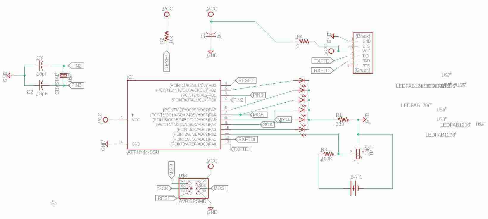
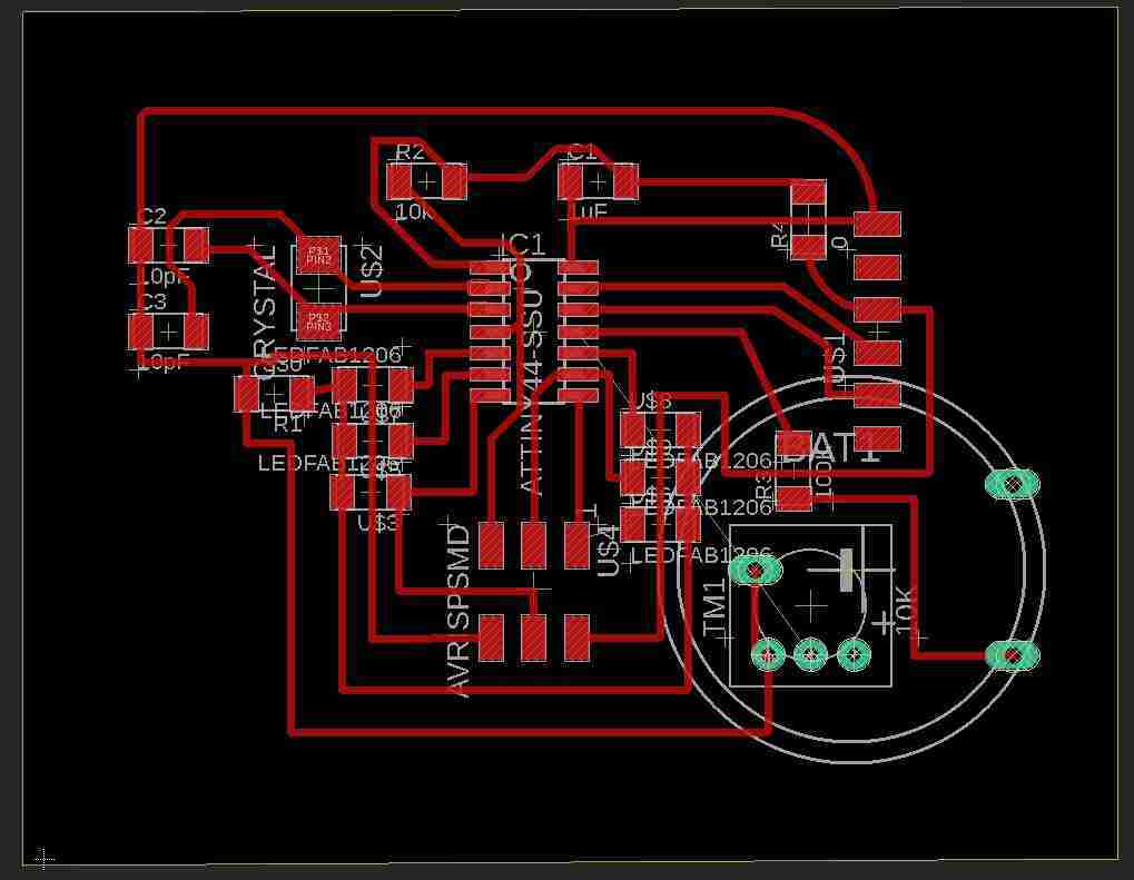
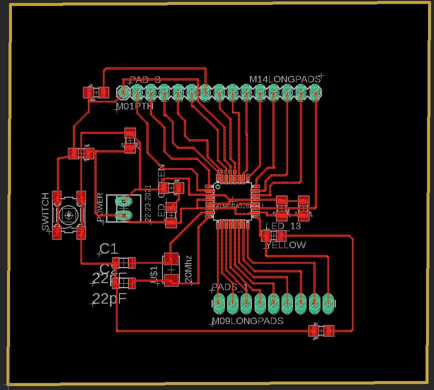
This is the schematic of the ATTiny44 digital board used for PWM.
This is the layout of the ATTiny44 digital board used for PWM.
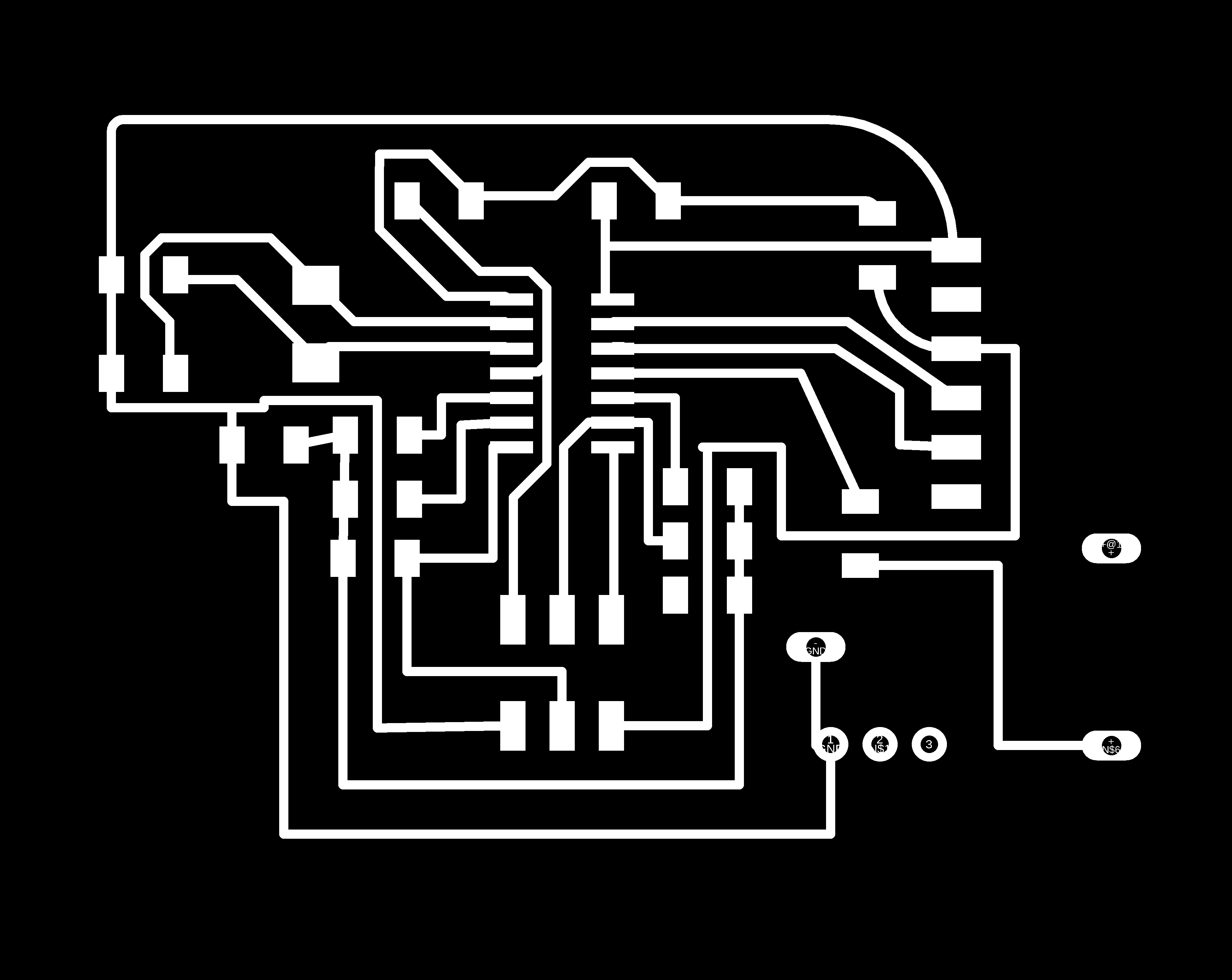
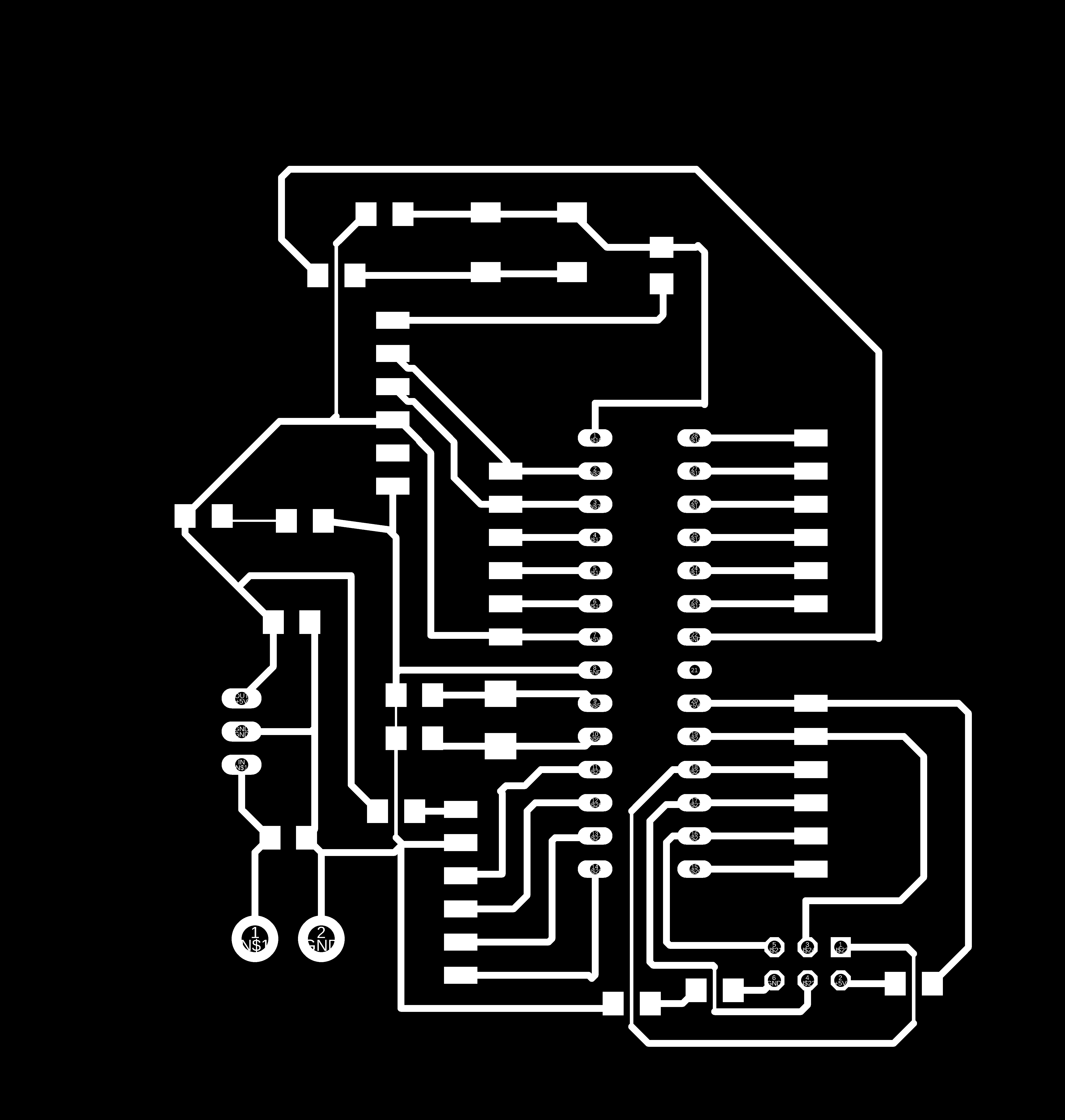
This is the exported png from Eagle for traces to be milled on Roland’s SRM-20.
This is the outline to be cut on Roland’s SRM-20.

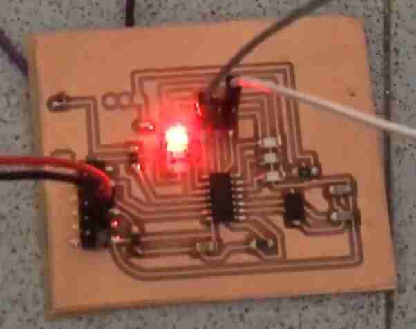
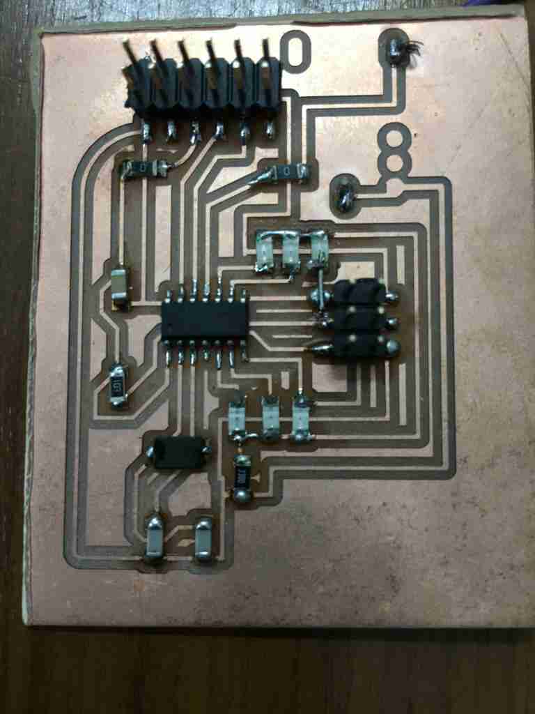
This is the ATtiny44 digital board in action.
Power board
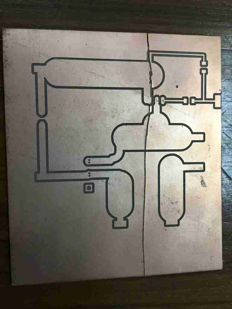
This is the schematic of the power board.
I used a trace width calculator to calculate the trace width for my circuit.
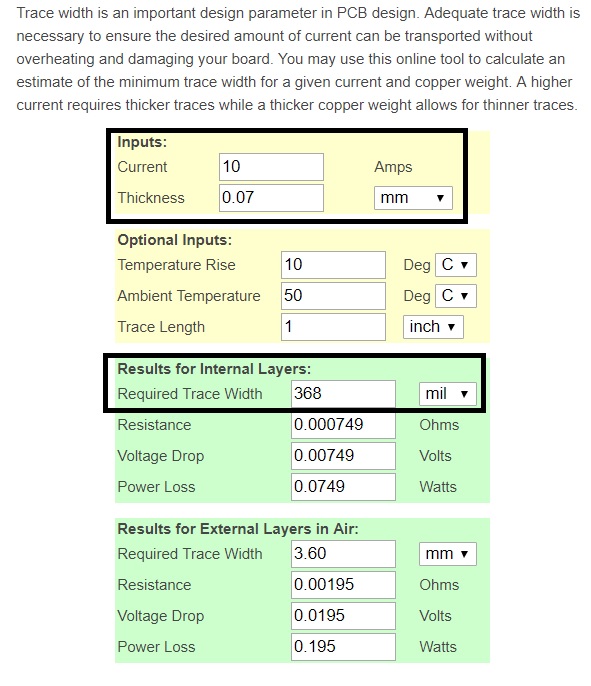
The trace width came out to be 368 mil for the internal layers. I used a trace width of 400 mil everywhere except the dc power supply as there wasn’t enough length available to place the traces. If I increased the length of traces then the board became too big to create an rml file on fabmodules.
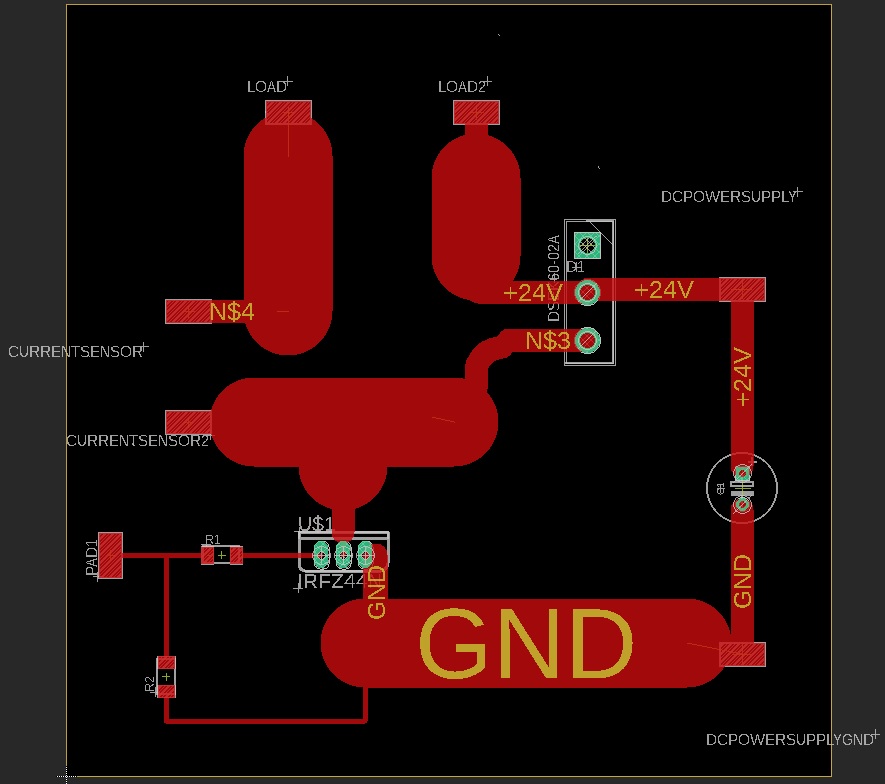
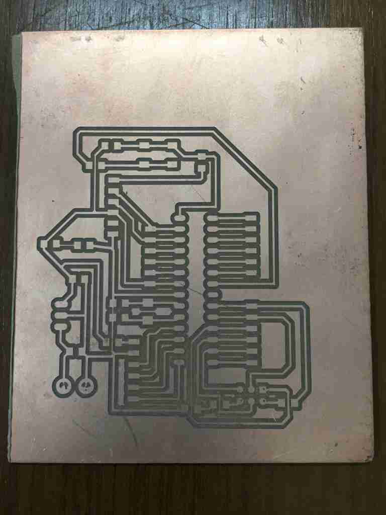
With this trace width, this was the resulting layout.
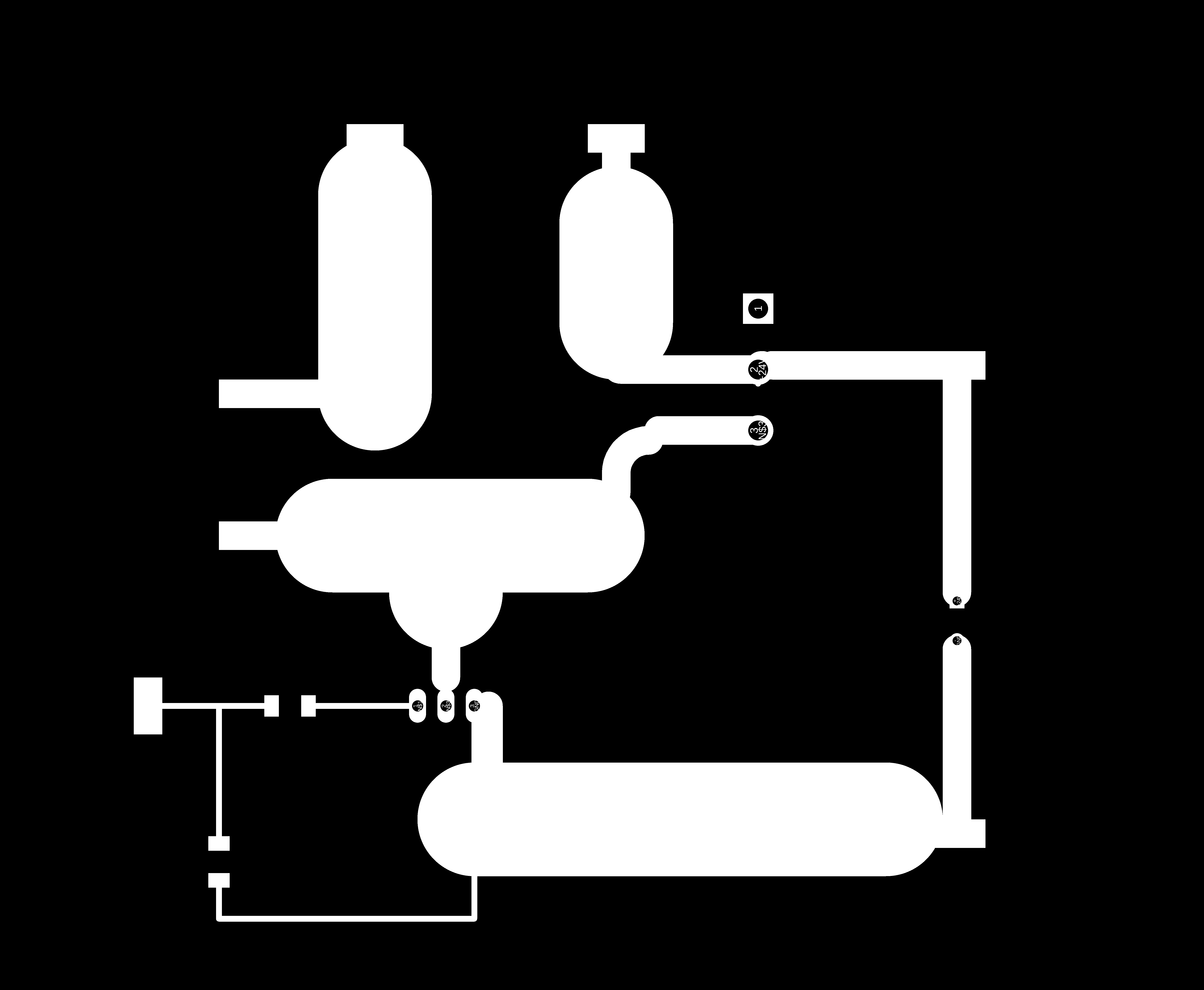
This was the png for traces which was used to create an rml file for milling the pcb.
This is the power board in action.
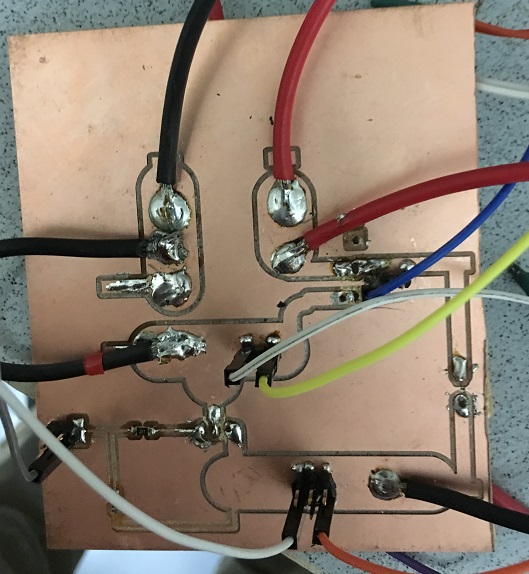
The MOSFET and the diode were connected in a perf board as per the image below as I wasn’t able to solder them properly on the PCB.
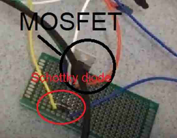
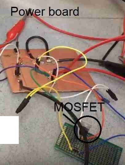
This shows the MOSFET and the power board together.
Problems faced and fixes
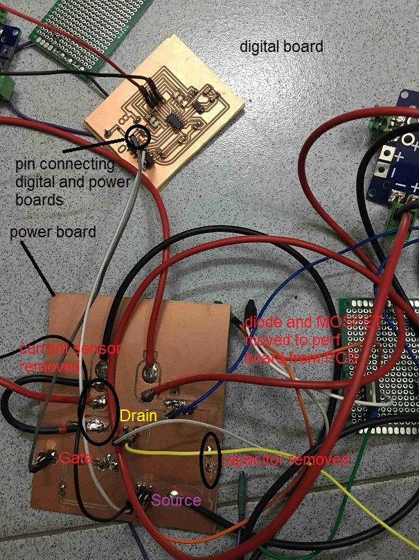
The below image shows the different connections in the circuit.
Problems and fixes:
-
This was the first time I was working with a power board and was a bit cautious as it involved 10 Amps or more of current. During my testing, I realized that my circuit stopped working when I attached the 470 uF capacitor in parallel to the 24 V DC power supply. May be the circuit was busy charging the capacitor as the capacitance was oversized. Si, I removed the capacitor and the circuit started working.
-
The current sensor was also causing problems with the circuit so I removed that also to further simplify the circuit.
-
I also had to place the MOSFET and the diode through hole components to a perf board as when I soldered them on the single sided PCB, the circuit wouldn’t work.
-
I also snapped a power board while trying to remove the milled power board from the bed of SRM-20. The tape had glued too hard and I was a bit quick. We need to have patience to remove the board.
PWM with LED strip
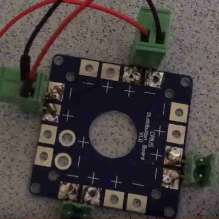
I used a power distrubtion board since I needed to supply 24 V to 24 V LED strip, 24 V DC motor and battery monitor circuit.
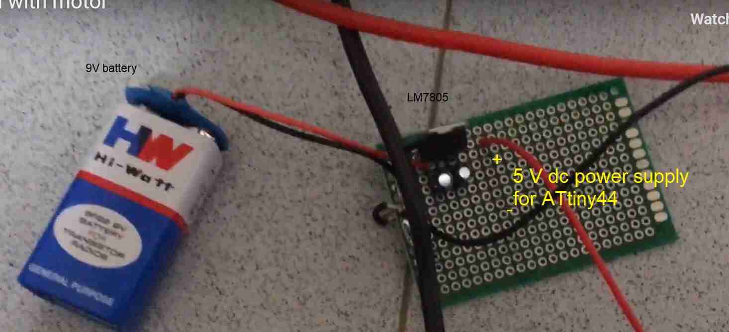
I also made a LM7805 circuit using a 9V battery to have a 5 V power supply for the ATtiny44.
This shows the connections for this 24 V LED strip circuit.
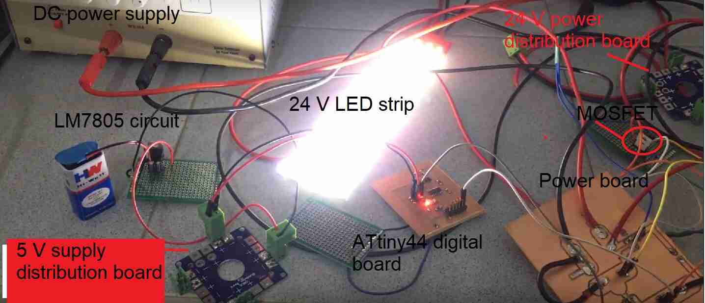
And this shows the fruit of hard work finaly. The LED strip running on the PWM code for fading in all its glory.
The arduino code used for the above circuit:
int led = 5;           // the PWM pin the LED is attached to
int brightness = 0;    // how bright the LED is
int fadeAmount = 5;    // how many points to fade the LED by

// the setup routine runs once when you press reset:
void setup() {
  // declare pin 9 to be an output:
  pinMode(led, OUTPUT);
}

// the loop routine runs over and over again forever:
void loop() {
  // set the brightness of pin 9:
  analogWrite(led, brightness);

  // change the brightness for next time through the loop:
  brightness = brightness + fadeAmount;

  // reverse the direction of the fading at the ends of the fade:
  if (brightness <= 0 || brightness >= 255) {
    fadeAmount = -fadeAmount;
  }
  // wait for 30 milliseconds to see the dimming effect
  delay(30);
}
PWM with DC motor
This shows the connections for this 24 V DC motor circuit.
And this shows the fruit of hard work. The DC motor running on the simple PWM code for fading.
Please note that the digital and the power boards were the same for the DC motor and the LED strip although I milled two each to use them together in my bike.
Output devices for the project
I wanted to share the link to the output devices that I have used in my project. This link shows the output devices i.e. 24 V DC motor/ 24 V LED strip. This whole section shows how the input devices and the output devices work together. I have also written my own code for this section to make the 24 V loads i.e. DC motor and LED strip work with the input devices. I use IRLZ44N MOSFET to control the output devices using the gate of the MOSFET as a switch using PWM with the throttle of my bike of the project.
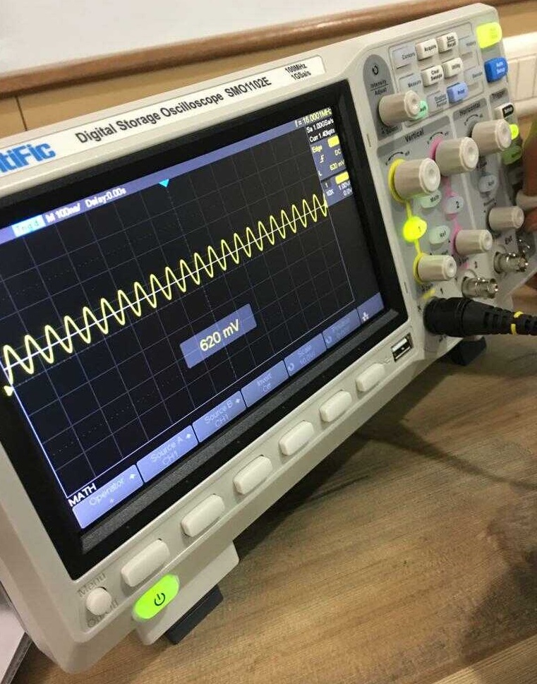
DSO to measure digital and analog signals
Our local instructor Rahul gave us a demo of how to use DSO. He connected the probes to the crystal of Ardunio Uno which showed a frequency of 16 MHz.
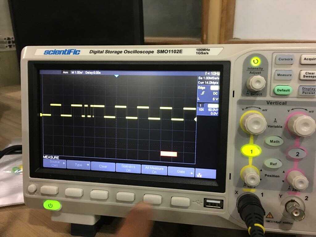
He also ran the LED blink program in Ardunio Uno and we observed the pulse signal on DSO.
Output devices interfaced with my pcb with atmega328p based on satshakit
Satshakit version 1
I also wanted to create an Arduino Uno of my own for this week. I used the Satshakit schematic for this purpose and modified it based on the components that we had and layouting it in Eagle by myself.
Satshakit with SPI pins
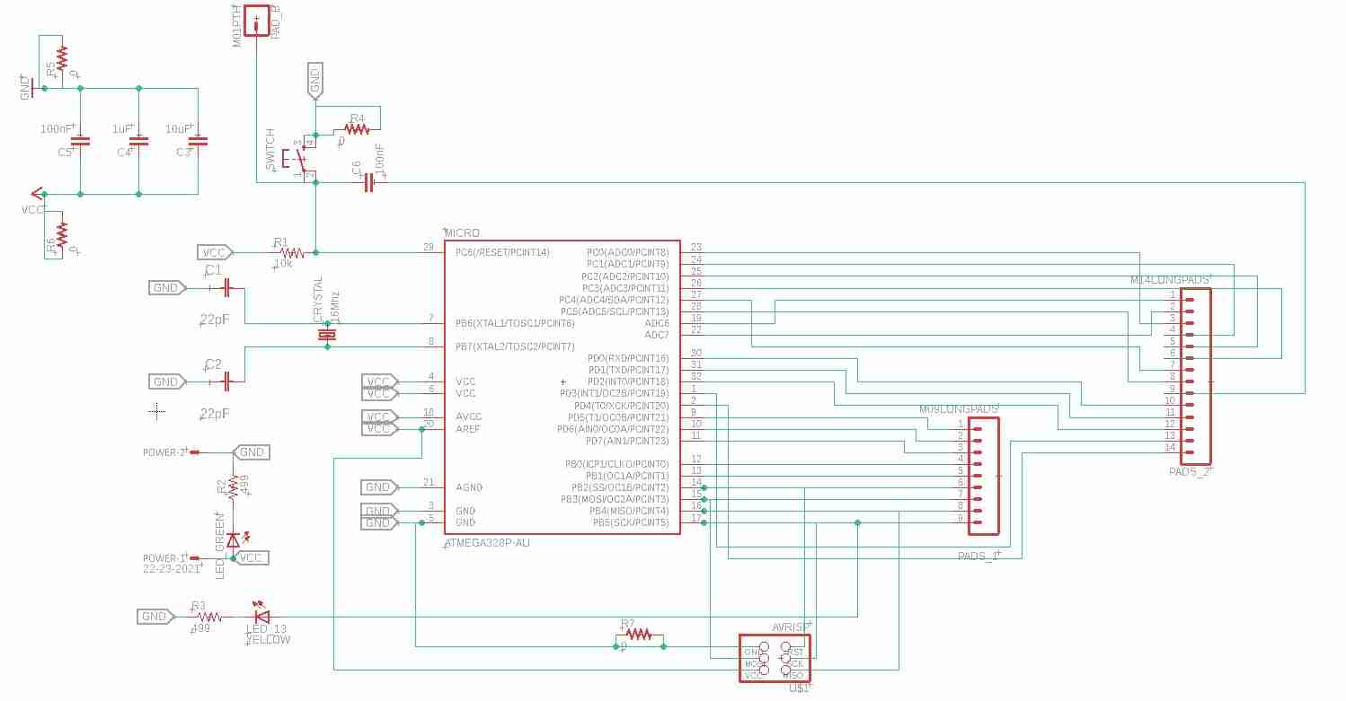
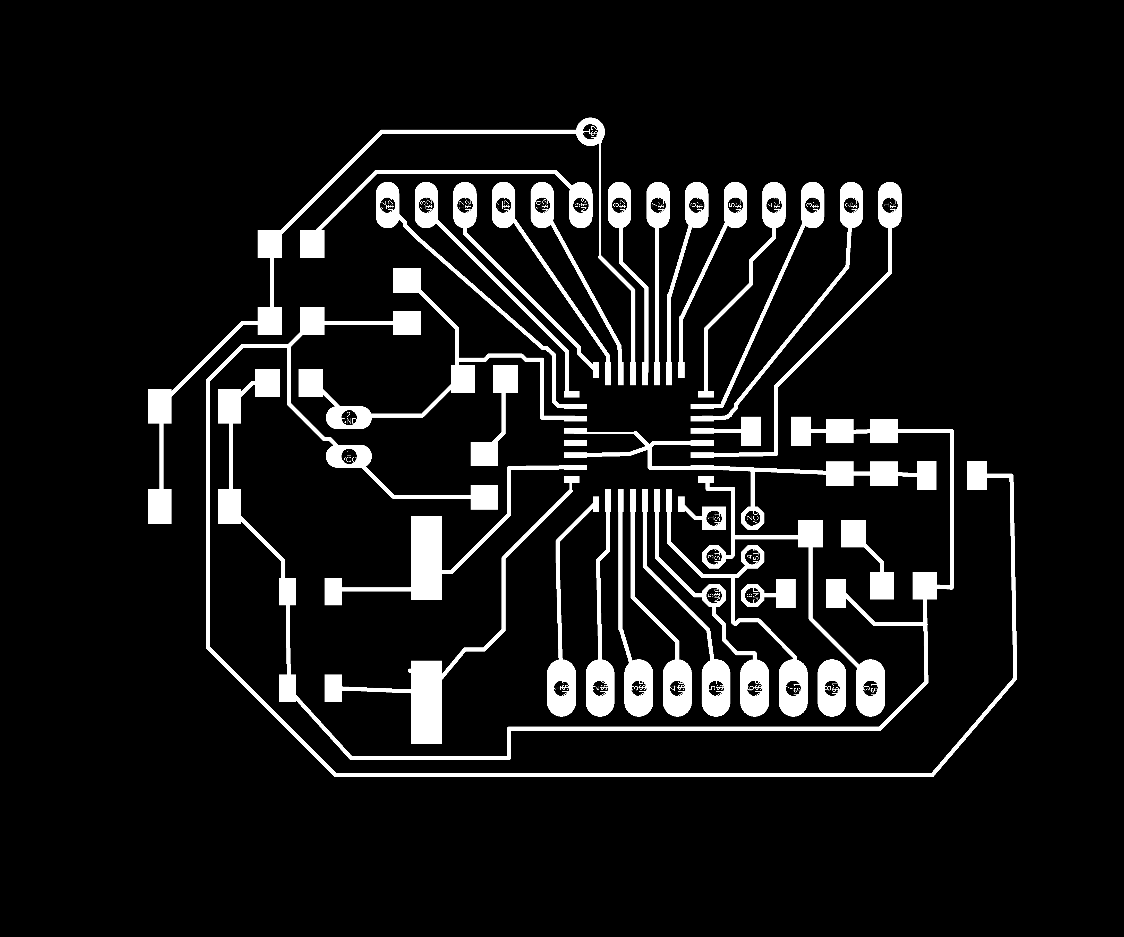
I also wanted to mill another version of Satshakit to include SPI based header pins for ease of use with programmers such as FABisp and USBasp.
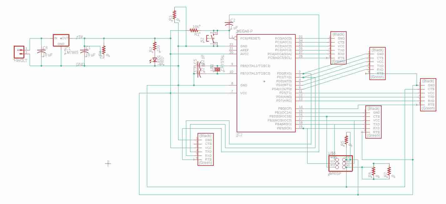
This image shows the schematic of it.
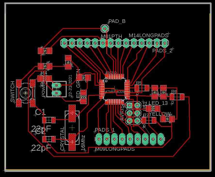
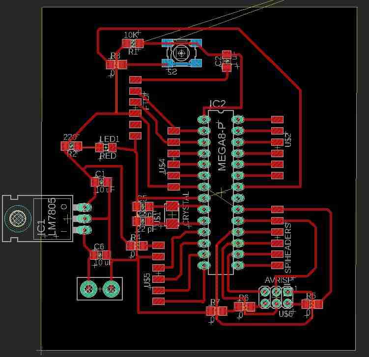
This is the layout.
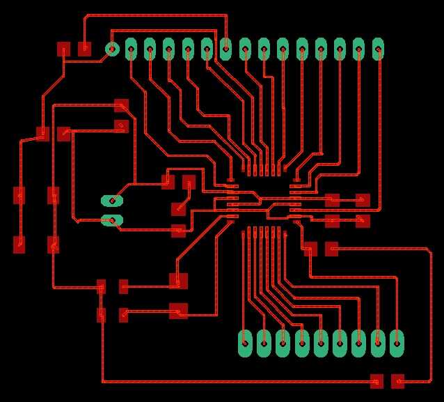
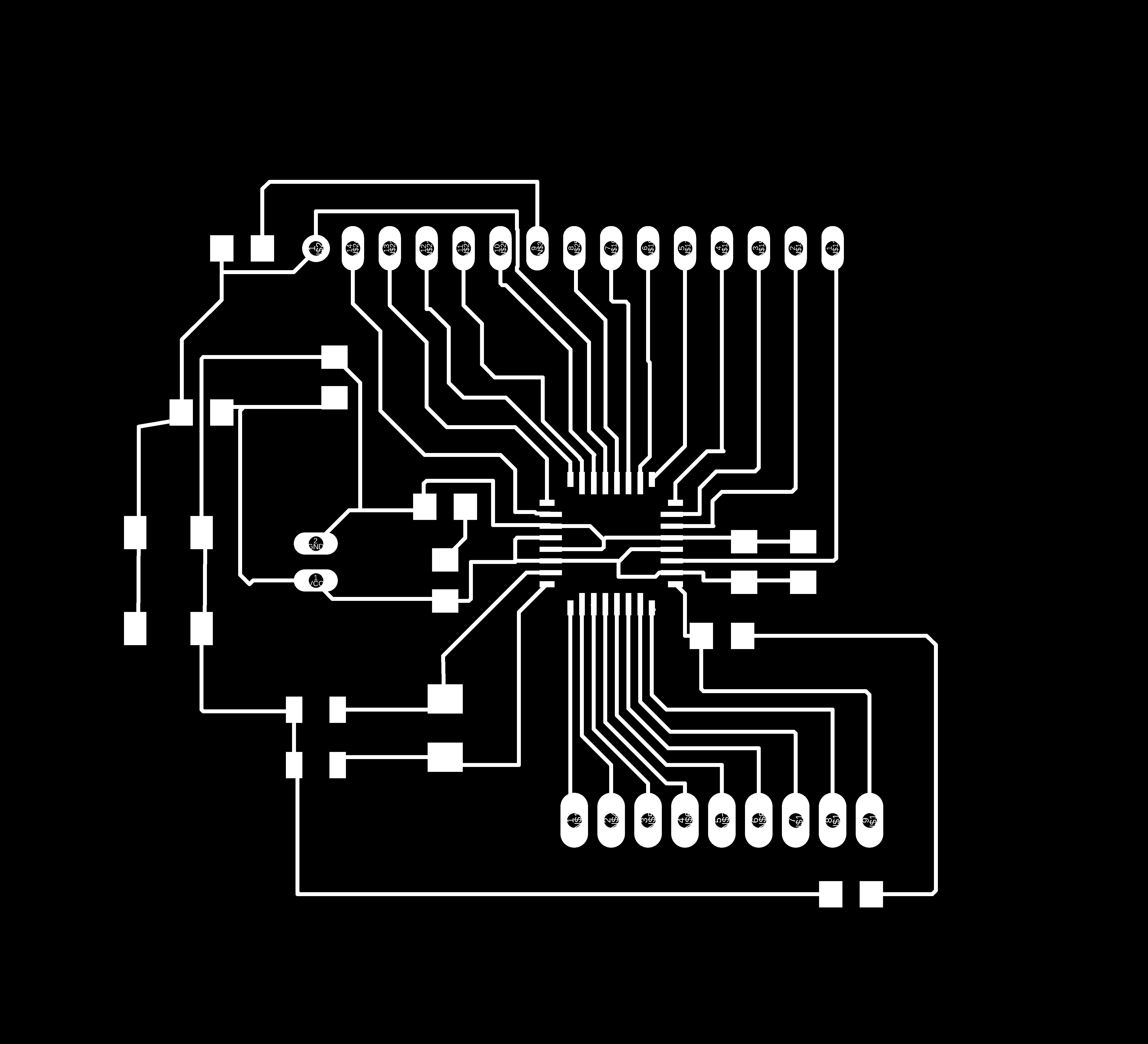
The corresponding traces.
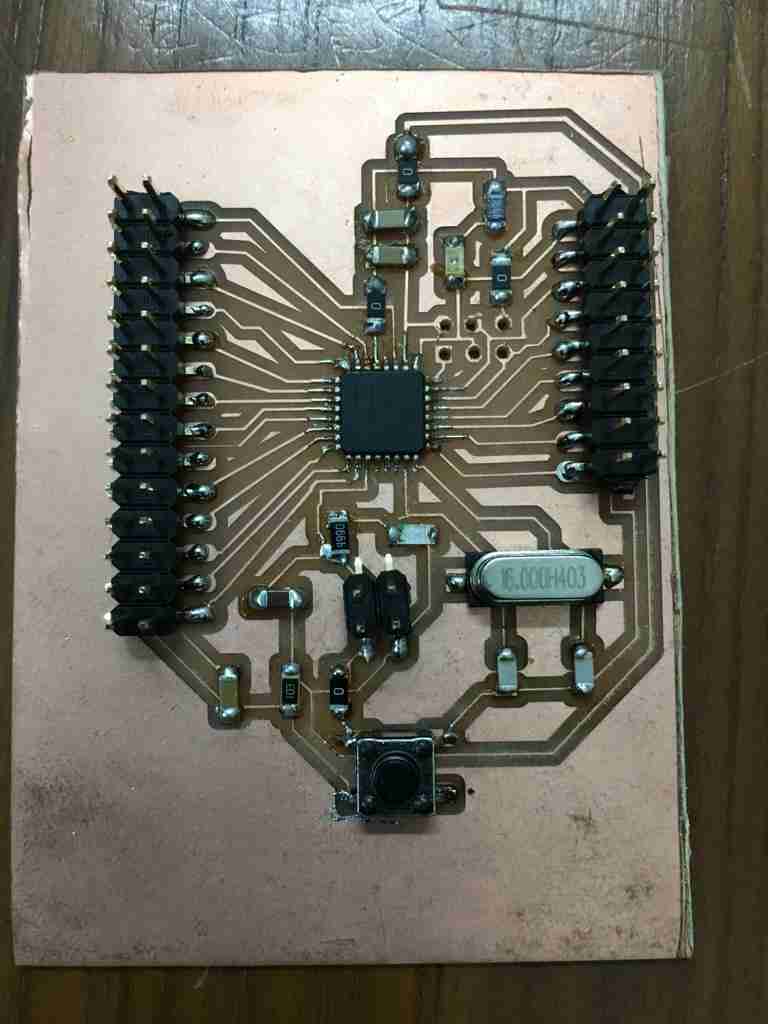
I have milled the pcb. I did have a few 10 mil traces but they came out fine with the 1/64 inch end mill bit. I have added the components to this board but I am getting errors when I burn the bootloader.
Atmega 328p DIP
I also created the schematic for a Atmega 328p DIP board to be safe as I wasn’t sure if traces of 10 mil for the SMD Atmega board would come out nice. This is the schematic for it.
The layout.
The png for it.
Designs and Codes
Download for the arduino code for datalogger with SD card.
Download for the arduino code with dht11 sensor.
Download for the arduino code to find the current time with real time clock module.
Download for the arduino code with the 4 segment display.
Download for the pcb related files for all the boards milled for this week.

Solar powered electric bike con kit by Jay Dhariwal is licensed under a Creative Commons Attribution 4.0 International License