4. Computer controlled cutting (Feb 13)
This week we were suggested to characterize the laser cutter and create a press fit construction kit using the laser cutter. We were also suggested to use the vinyl cutter and make a sticker or more.
I really liked the work we did this week. I had used a laser cutter before but I had never characterized it. Ashish in our group at AKGEC had prepared a series of tests which helped us to find out how best we could use the laser cutter for our designs. The methodology that we followed would be applicable to any other machine that we would like to use.
Characterization of laser cutter (Group Assignment)
How to operate the laser cutter?
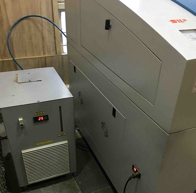
I hadn’t used this laser cutter from RDWorks before. So, first step was to understand how it works. I downloaded and installed the software which runs this laser cutter. We switched on the mains power, then switched on the coolant system and the laser cutter. The water in the coolant system needs to be changed once a month and the temperature should not go beyond 30 degrees C.
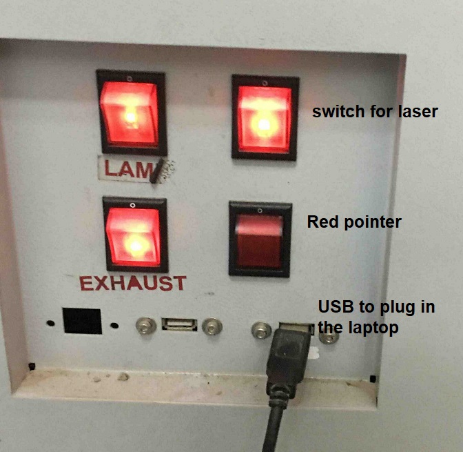
Next, we started the switched for the exhaust system, lamp for the laser cutter and the red pointer for the laser. Next, we connected our laptop with the file ready on the RDWorks software with the USB cable to this interface. The laser switch was started only when we were ready with the work piece on the laser cutter bed.
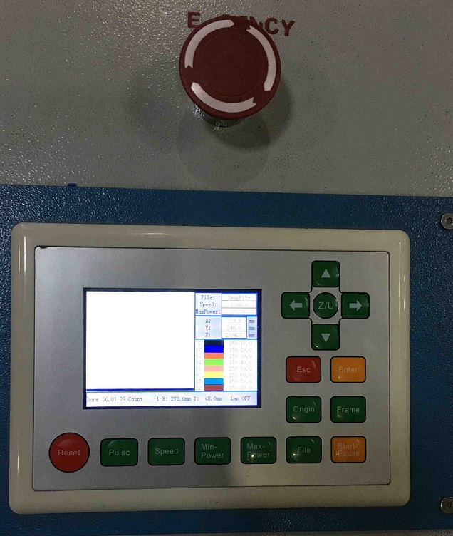
We wanted to understand how to use the control panel to operate the laser cutter. The z setting moves the laser to move up and down (with the left and right arrow keys) to focus the red laser pointer. Enter button completes the action. The up, down, right and left keys by themselves move the laser on the bed in x and y direction. Once you have placed the workpiece, you can set an origin and press enter to confirm. In case of fire, press the emergency stop immediately.
RDWorks software interface
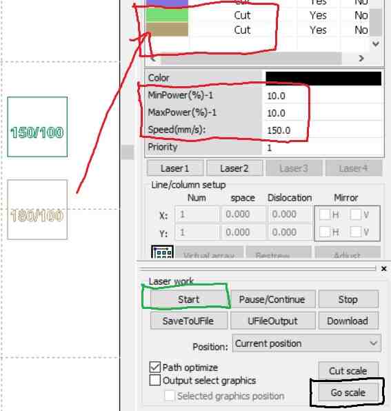
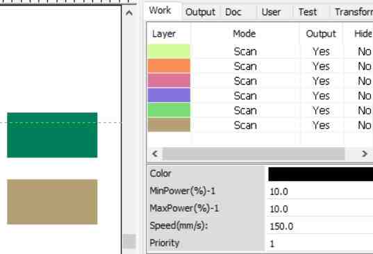
Next step is to open the RDWorks interface and import the CAD (dxf, etc.) file. The parts of the file need to be color coded for cutting or scanning. In the below image, brown color is assigned to a filled rectangle to cut at a power of 10% and speed of 150 mm/sec. Upto 20 colors can be assigned at a time. Next, we select ‘Go Scale’ to make a dry run of the frame of the laser system on the work piece to make sure that the coordinate settings are correct. If not, please go to the Config, System Setting to choose the laser head appropriately. Once, you are satisfied with the ‘Go Scale’ setting, click on ‘Start’ to run the laser.
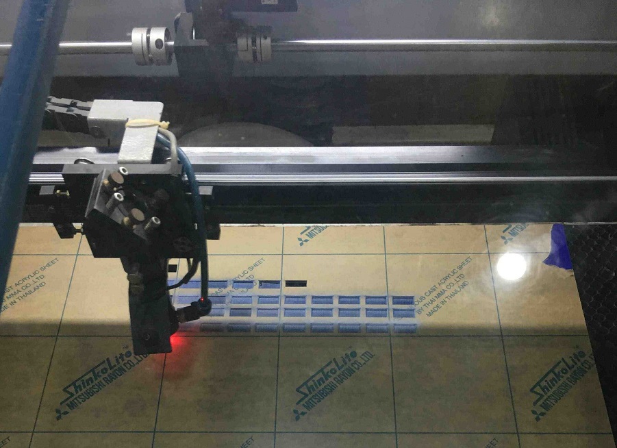
We tried a test piece on it.
Laser cutter experiments
Next step was to run the experiments to characterize the laser cutter.
Speed power test
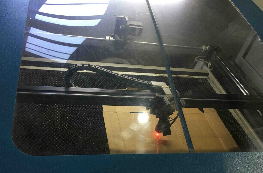
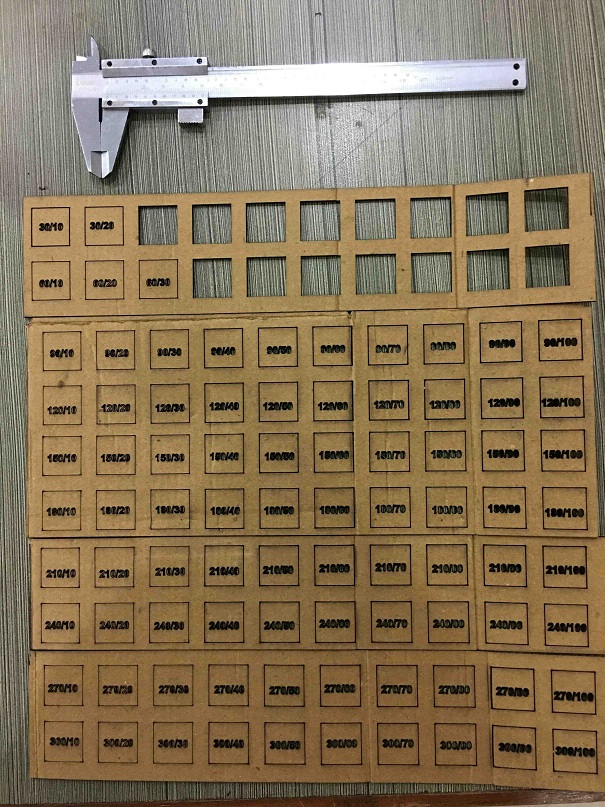
First, we wanted to know what speed and power setting should be used to run the laser cutter for this cardboard of thickness of 2 mm. We want to conserve energy so we would like to know the minimum speed power combination.
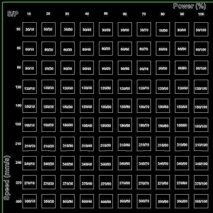
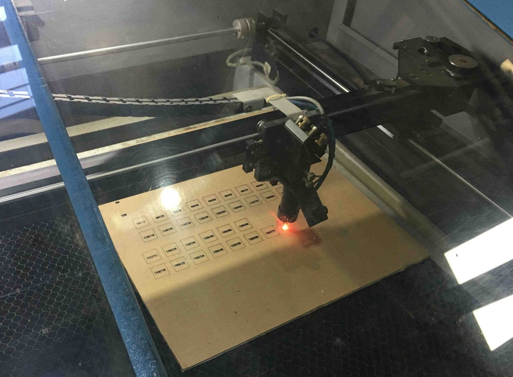
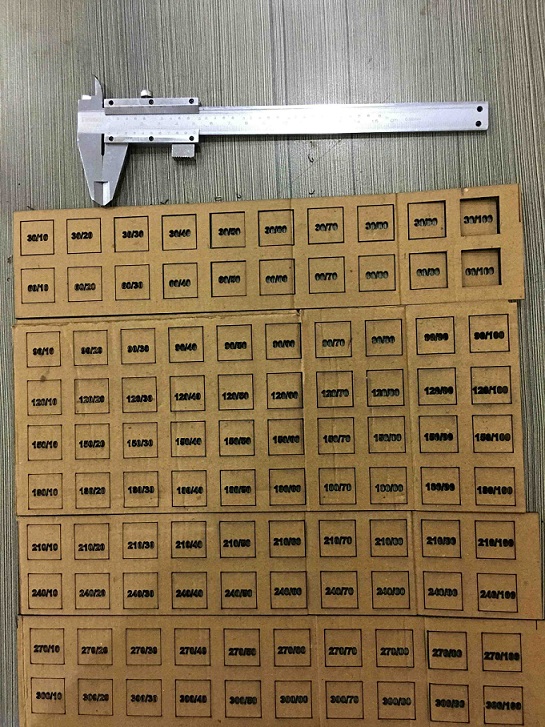
The laser fully cut the cardboard at a speed of 30 mm/sec and power of 30%. To be safe, we went with the speed of 40 mm/sec and power of 40%.
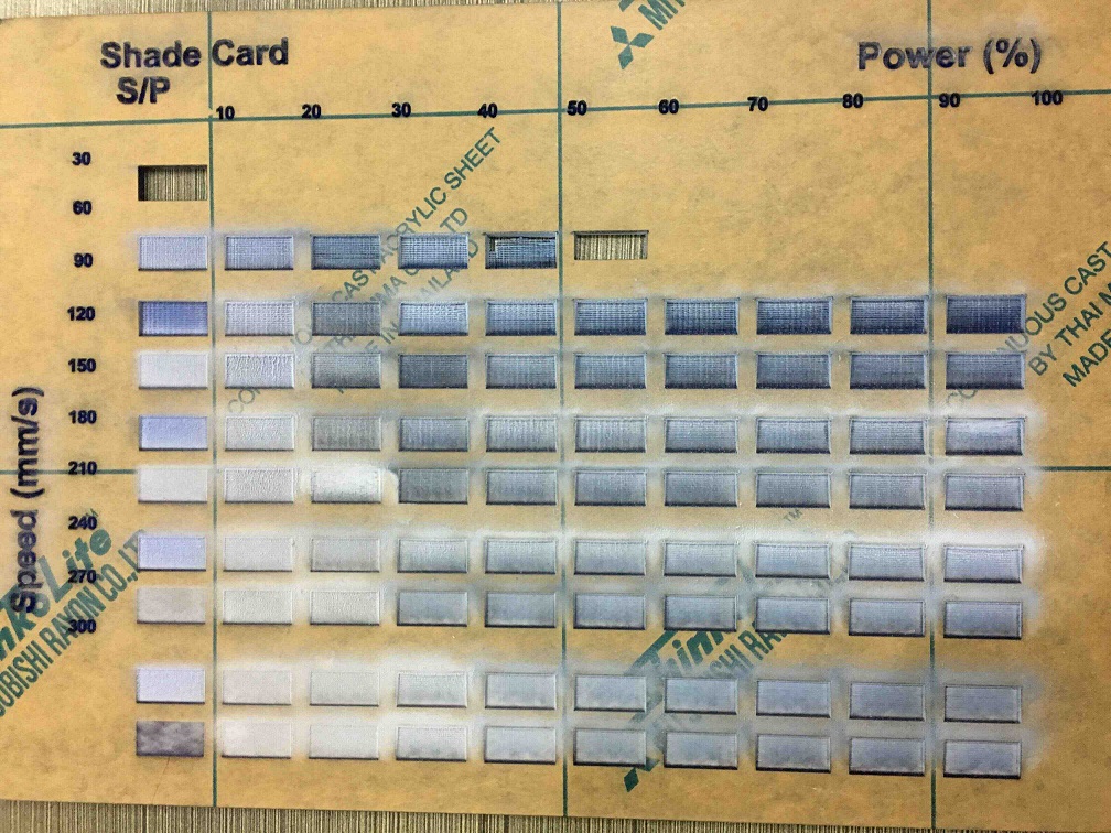
Raster test
For the raster test, we have to use the ‘Scan’ mode on the RDWorks software interface.
The shade card shows the engraving quality at different speed and power settings.
kerf test
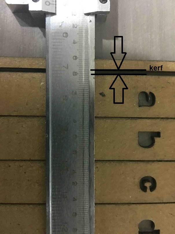
Kerf is an important parameter to understand. Kerf is the thickness of the material which gets burned off by the laser during cutting. One good way to measure Kerf is to make 10 cuts within a rectangle, shift all the cuts to one side, measure the gap and divide it by 10 to get the average Kerf.
Here, we used a speed of 40 mm/sec and power of 40%.
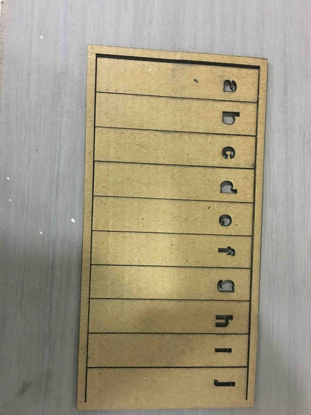
The kerf came out to be 3 mm/10 ~ 0.3 mm. Kerf is therefore important to bear in mind while designing as this material which is burned off would be used to set the tolerances appropriately. We should also note that the Kerf would be dependent on power and speed settings of the laser cutter.
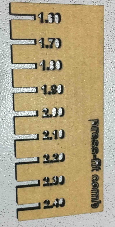
Press-fit comb test
This is another good way to know the thickness of the comb in which the cardboard ‘male’ piece would press fit. 1.6 mm was about right but I went with 1.5 mm thickness, it felt to fit better. I forgot to take a picture of the extended comb with a thickness of 1.5 mm. From what I remember, the power of 90% and speed settings of 30 mm/sec were used for this test.
Press-fit construction kit
Parametric modelling
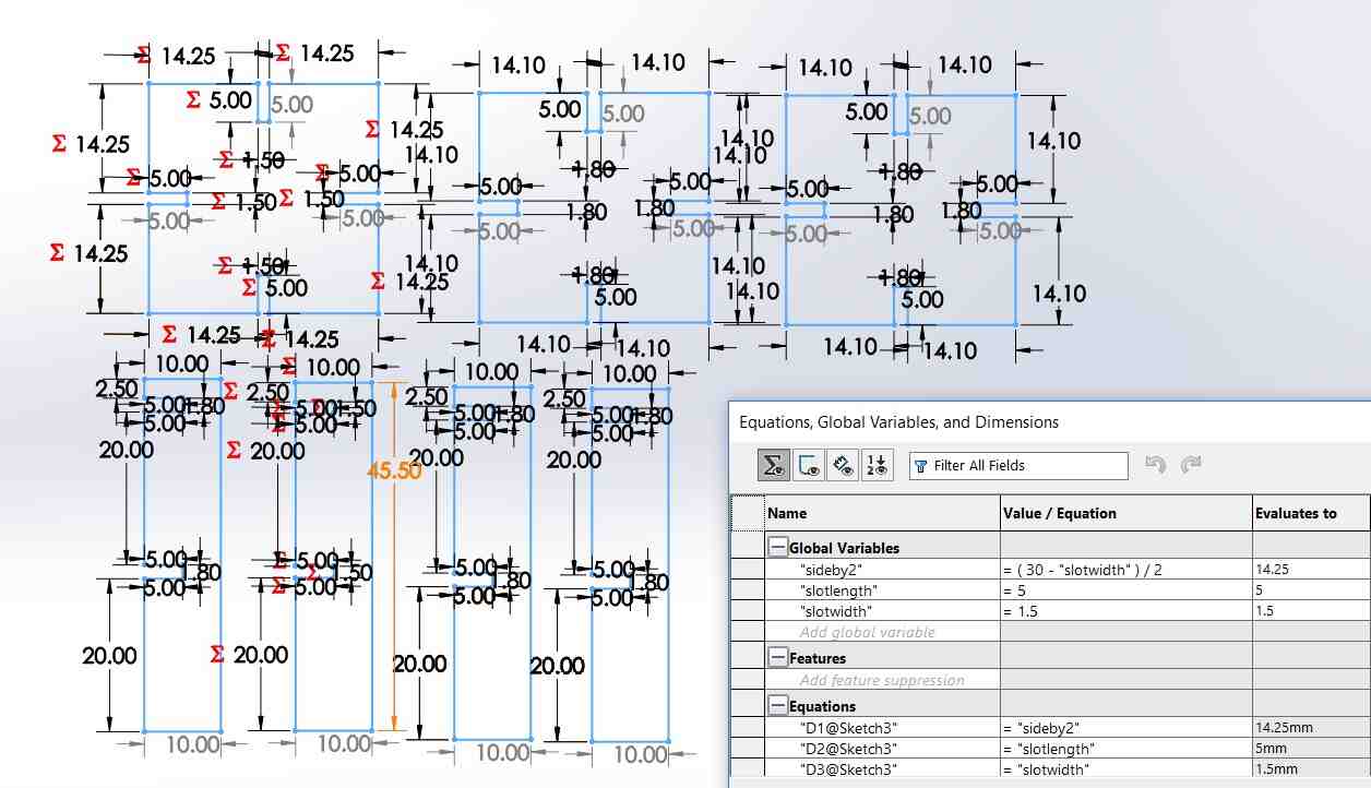
I used Solidworks equation editor for parametric modelling. I was inspired by the press fit furniture shown by Neil in class and wanted to make a small scale version of it. I also found this pen holder to be interesting. Neil had also shown this square with slot as a repeating block. So, I went with two building blocks - a square and a leg as repeating blocks using the cardboard.
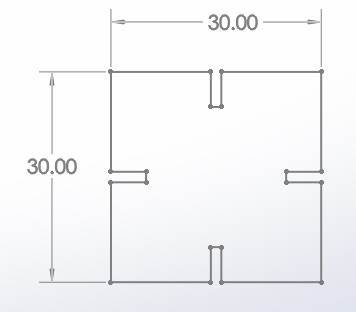
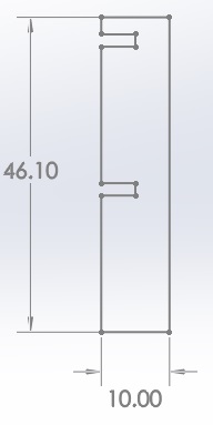
I made a parametric model with Solidworks. This image shows how the parametric value of slotwidth could be varied which would automatically change the other parameters. If the slot width was 1.9 mm then the other dimensions would change accordingly as per the image below.
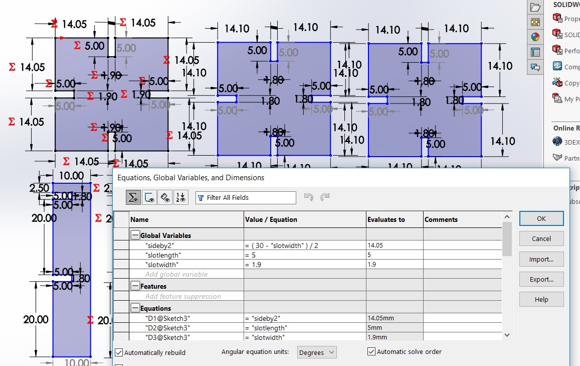
But for our case, for the square and the leg to press fit, for the cardboard thickness of 2 mm, we had found from the press-fit comb test that the slot thickness of 1.5 mm would be the most appropriate. So, accordingly, the slot width is changed to 1.5 mm in the parametric model below.
Press fit kit possibilities
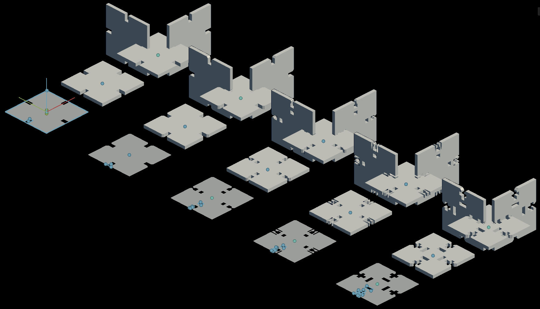
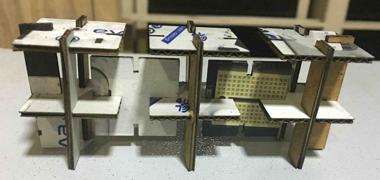
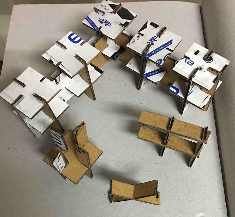
These dimensions were finalized to laser cut these pieces to build the press fit construction kit. The below images show different combinations in which these blocks can be combined. There is scope for improving this design but it teaches the essence of what is possible. The power and speed settings were the same as the press fit comb test.
The below image shows the pieces combined to form 3 tables together.
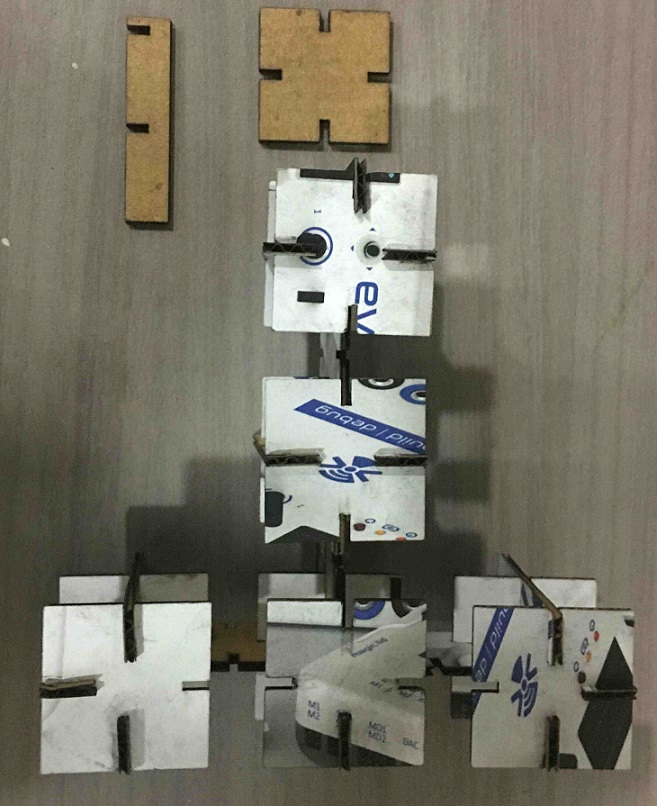
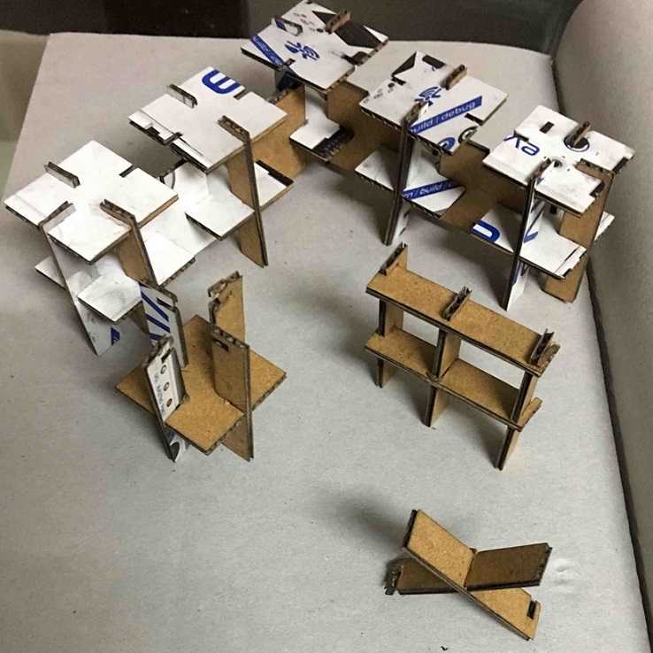
The below image shows combining the pieces in a T-shaped layout consisting of 5 tables.
This image shows another view of the T-shaped layout.
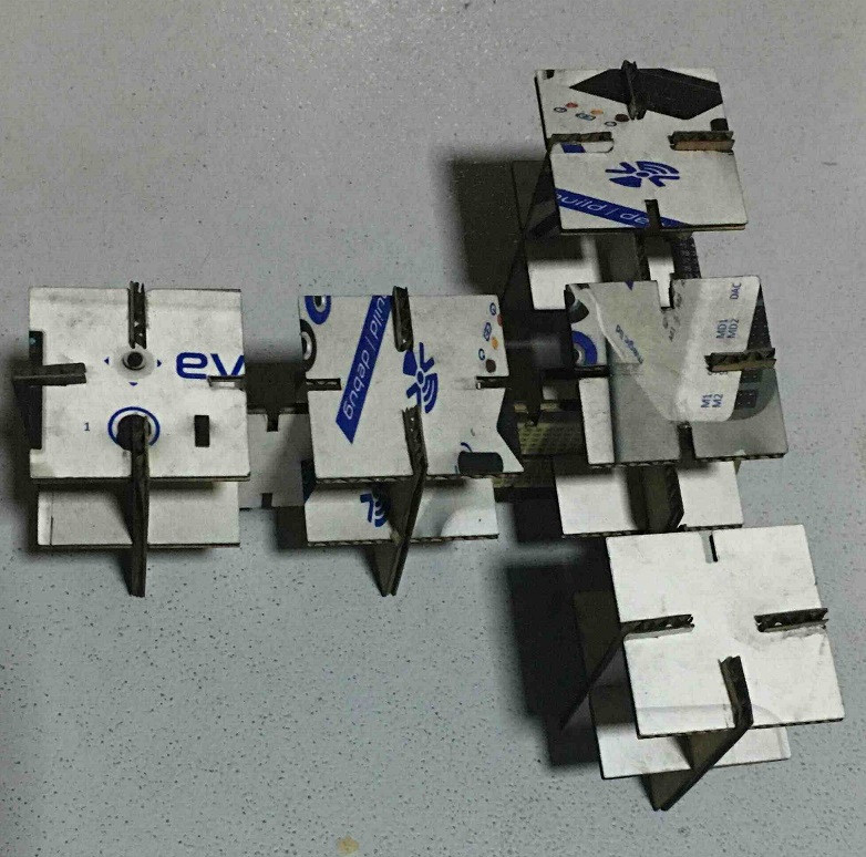
This image shows the tables combined in an L-shaped layout. This layout could be replicated endlessly.
We also see other possibilities with such two pieces of a square and a leg.
Learnings
We learnt about how the kerf plays a role in getting the right tolerances in our design. We also found out that the kerf depends on the power and speed of the laser cutter. The more the power and lesser the speed, the higher the kerf.
Please note that the kerf test and the press fit comb test were done at different power and speed settings so the kerf for the kerf test was 0.3 mm but for the press fit comb test and making of the press fit kit, the kerf was ~ 0.5 mm.
Vinyl cutter
We recently bought a Roland GS-24 machine for the place of my work at IIT Delhi and we have a Graphtech CE6000-60 vinyl cutter in our AKGEC fab lab. I did most of my work on the Roland GS-24 machine as this was more accesible but I also explored the Graphtech cutter.
Roland GS-24
I wanted to make the traces of flexible pcbs using a vinyl cutter since I had used vinyl cutter with vinyl sheets before.
Sheet preparation
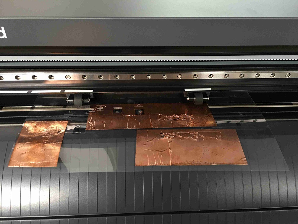
I had copper foil available with me. Since that is not hard enough a surface so to protect the blade, it needs be placed on a vinyl sheet or something which I felt could be even better is acetate films used with OHP projectors in older days. So, I put the copper foil on acetate films to be used with the cutter. This copper foil had a few wrinkles in them but since this was to be used for initial tests so this was okay. The better copper foil was saved for later.
GS-24 setup
I did follow few video tutorials to get a hang of how to use Roland GS-24 i.e. link 1 and link 2.
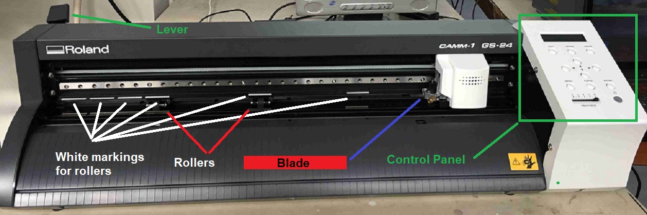
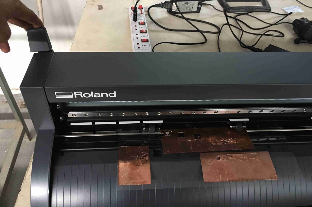
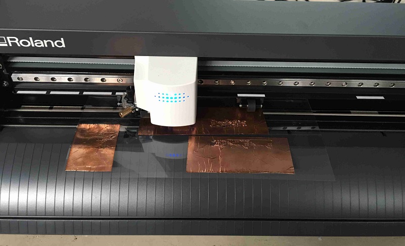
Roland CAMM1 GS-24 plotter and its different components can be seen below.
The prepared sheet is placed in between two rollers on the plotter.
Then the lever is pulled to clamp the sheet snugly in between the rollers.
Next, we press the power button on to start the machine.
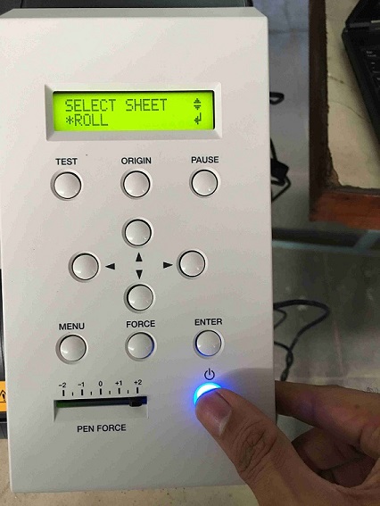
We press Enter to select the sheet as a roll. The other choices are to select the sheet as an edge or a piece.
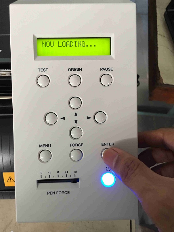
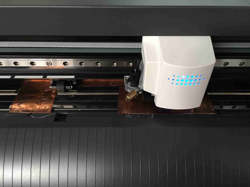
Once the sheet is selected as a roll, the controller moves in between the rollers.
The controller also calculates the width of the sheet in between the rollers and displays it on the screen.
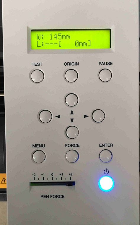
We can then move the controller in x and y direction using the arrow keys. This depends on where we want to make a cut.
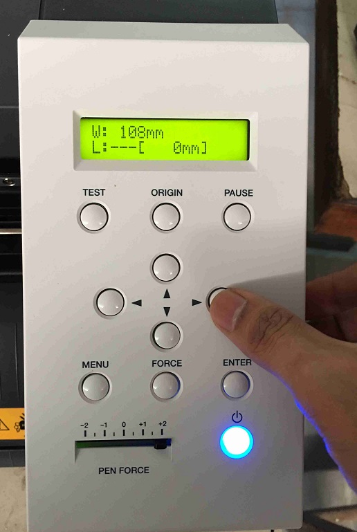
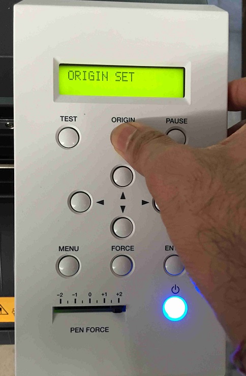
Once we are happy with the position of the controller, we can then set it as the origin.
We need to press the origin button until it blinks and then the screen changes to the width and length screen.
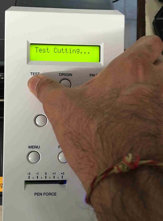
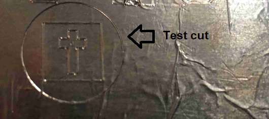
We are ready to try a test cut inbuilt in the cutter.
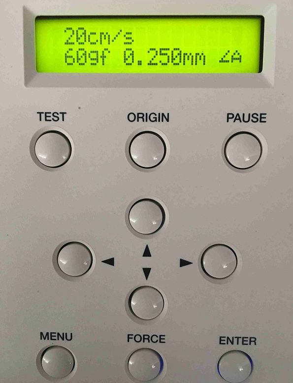
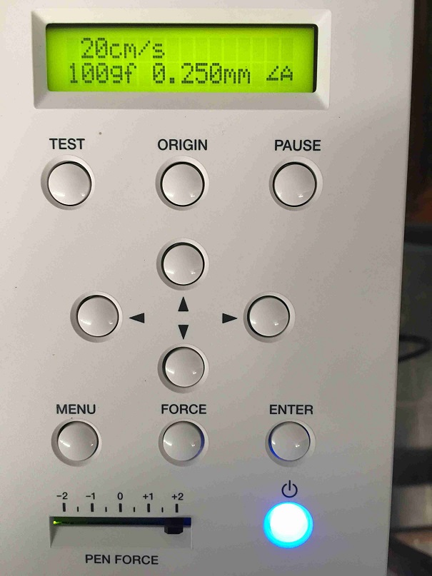
We can press the Menu button to see the current settings of the force and speed.
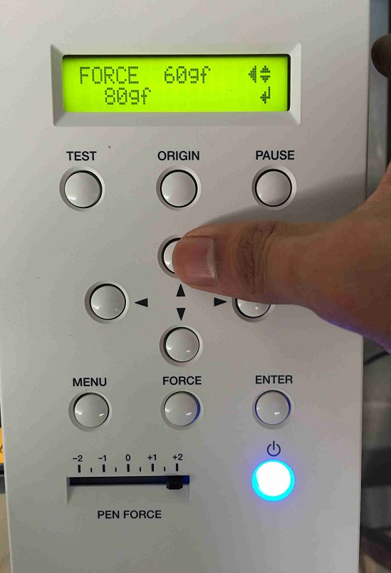
We can press the Force button to increase or decrease the force. We have increased the force from 60 gf to 80 gf.
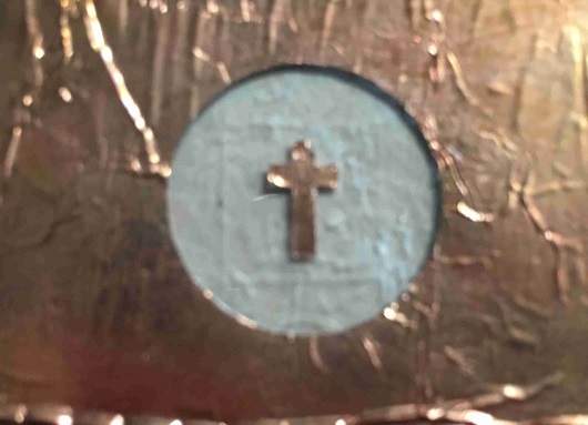
The test cut consisting of a cross in a square in a circle. The force of 80 gf still doesn’t seem to be enough as the copper foil may not come off the acetate film yet.
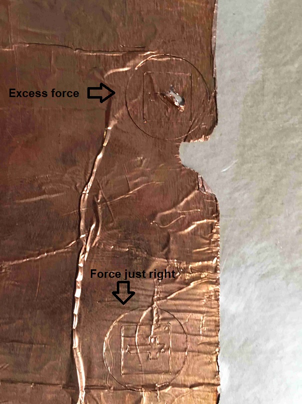
We increase the force to 110 gf which seems to be excess as the copper foil comes off prematurely and the cut gets spoilt. We decrease the force to 100 gf which seems to be just right.
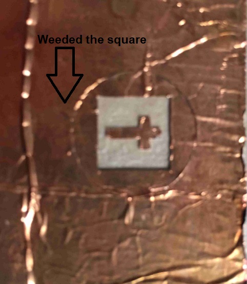
We now weed the square. The weeding is proper. It justs requires a lot of patience and force to remove the unwanted copper as it is glued very strongly to the acetate film. Copper doesn’t peel off very easily so it seems that the transfer tape may not work.
This image shows the weeding done with the help of tweezers.
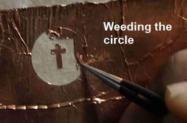
The weeded circle also looks pretty good.
The optimal force is 100 gf. The speed can’t be changed here. We would need to change it through a software on the computer.
CutStudio
Next step is to find a software which can send our design to the cutting plotter. Roland CutStudio is a software which comes with Roland GS-24. It is easy to use.
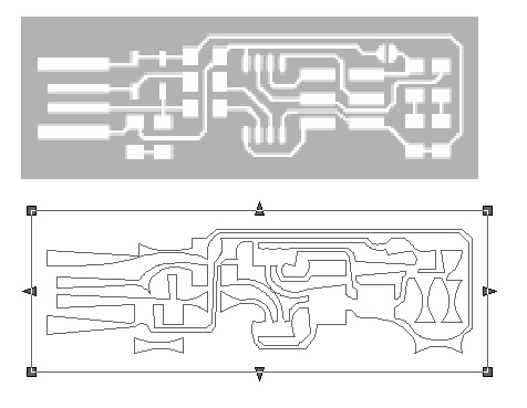
I imported an png in this software to trace the outline using Extracted Contour Lines function in the image outline feature with many different tweaks.
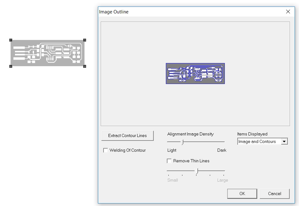
But the outline didn’t come out alright :(.
Vectorizing the image to cut
I then had to find another software which wouldn’t distort my image. Cut Studio works as a plugin with CorelDraw X6, X7, X8 and 2017. I downloaded CorelDraw X8 and added the CutStudio plugin. The instructions for how to add Cut Studio as a plugin come with the Read Me file in the installation folder.
I took the Brian’s Fab ISP image with fabmodules and vectorized it in svg format which can be opened with Inkscape.
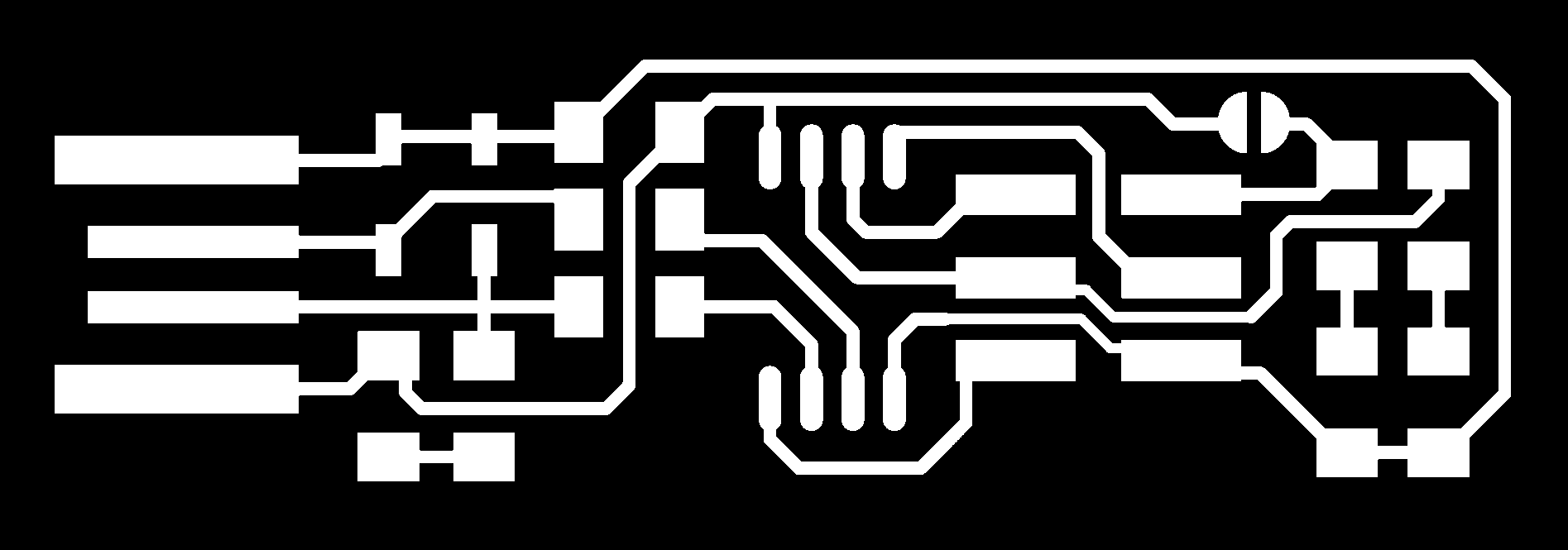
I inverted the image as I just needed to trace the outline.
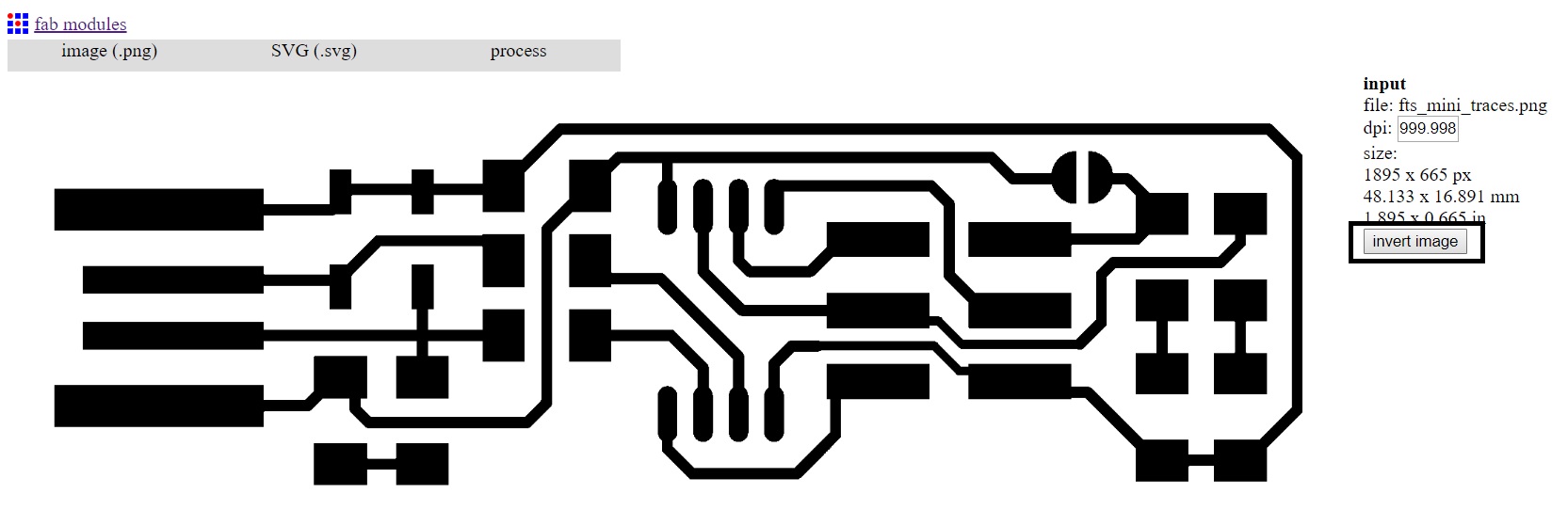
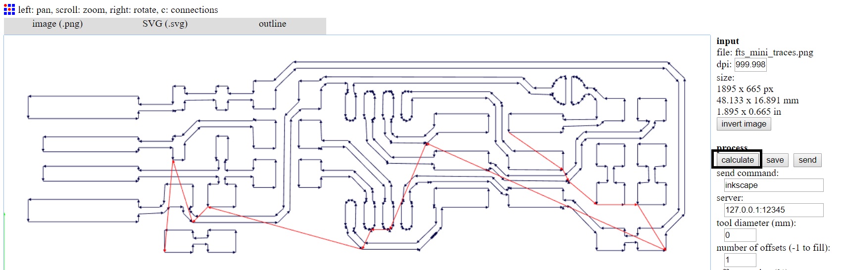
I then calculated the image to get the outlines of the traces and saved the svg file.
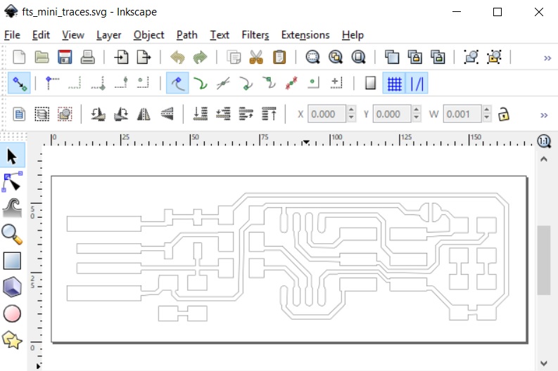
Next, we open the svg traces file in CorelDraw X8 and use the CutStudio plugin to transfer this vectorized file.
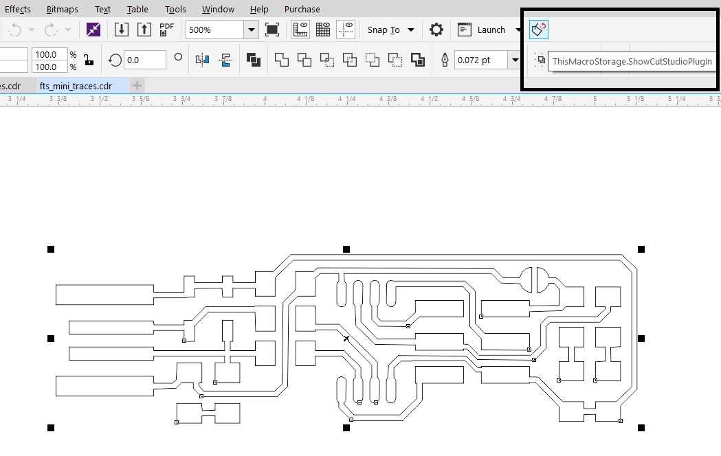
Click the button to open this file in CutStudio.
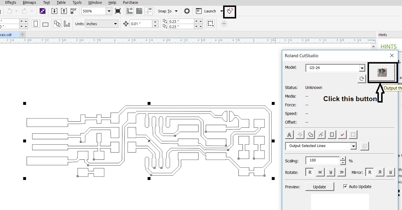
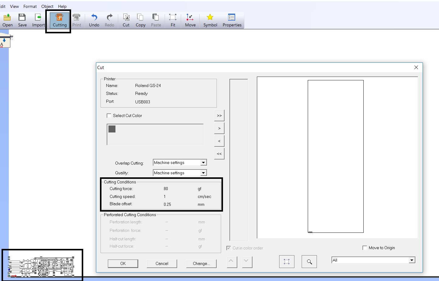
This vectorized file opens in CutStudio and we need to click on the Cutting icon and set the right force and speed to cut with the plotter.
Flexible PCB making and weeding
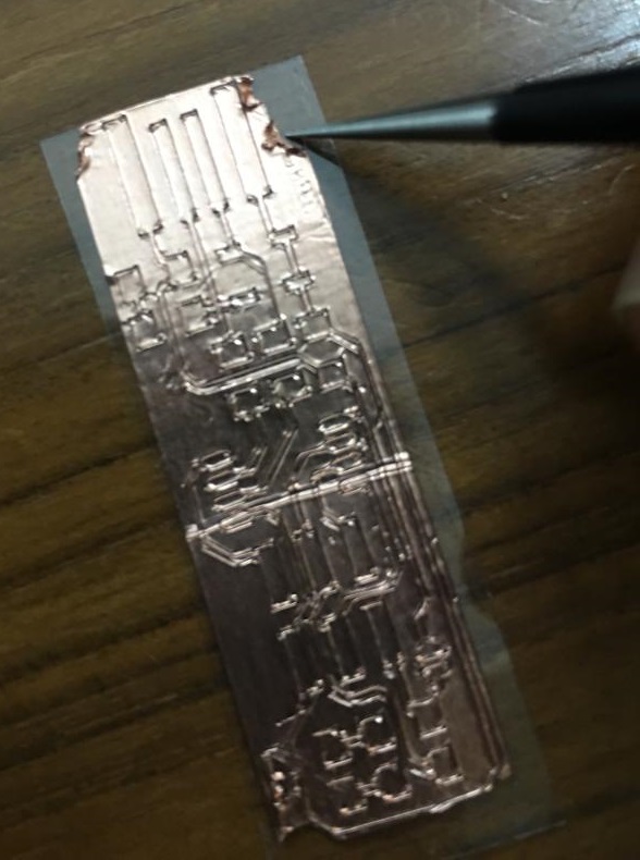
So, with the optimized force of 100 gm and reducing the speed to 1 cm/s, I cut the flexible fab isp as per the below video.
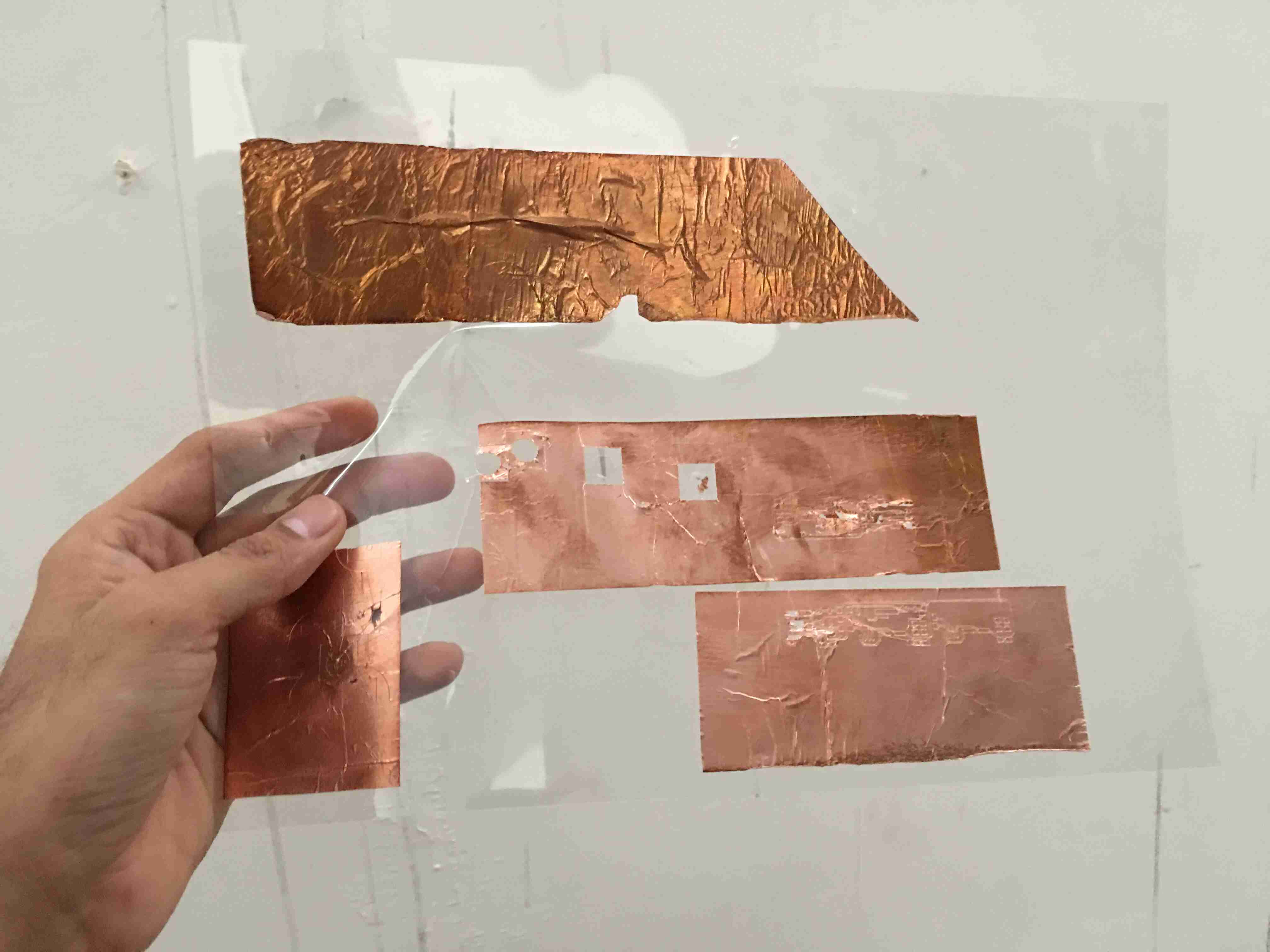
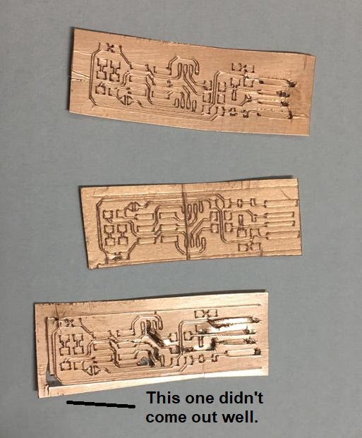
These were the three fab isps that I cut with the plotter. Two of them came out well. One of them didn’t.
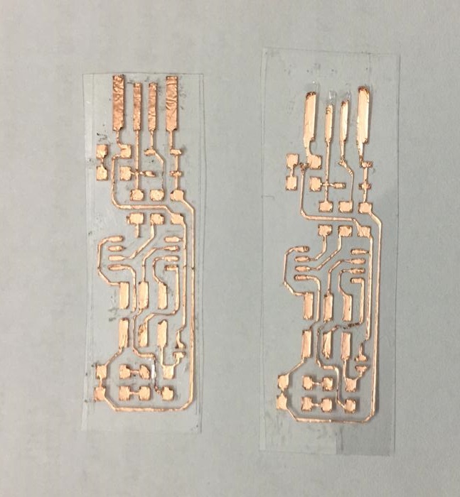
I started weeding the two fab isps which came out well.
This is how the weeded fab isps looked like. I don’t think this was bad at all for the first try.
The traces which got missed or got very thin have been shown in black.
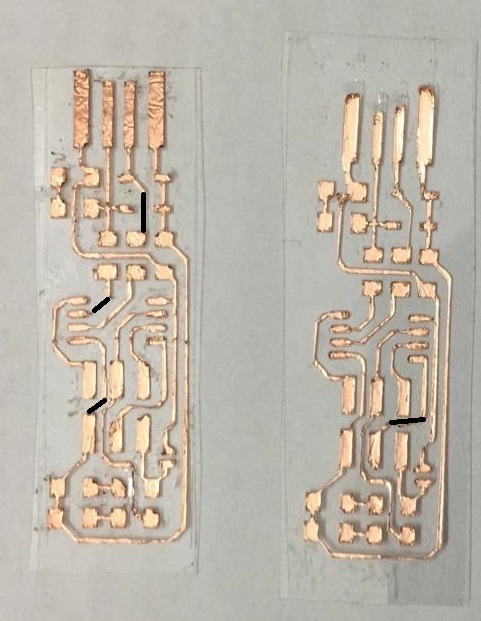
Although the plotter took less than 5 minutes to cut the fab isps but the weeding process took very long. It is easy to make mistakes. For simpler circuits with trace width of 16 mil or more, I would use flexible pcbs but not for complicated circuits.
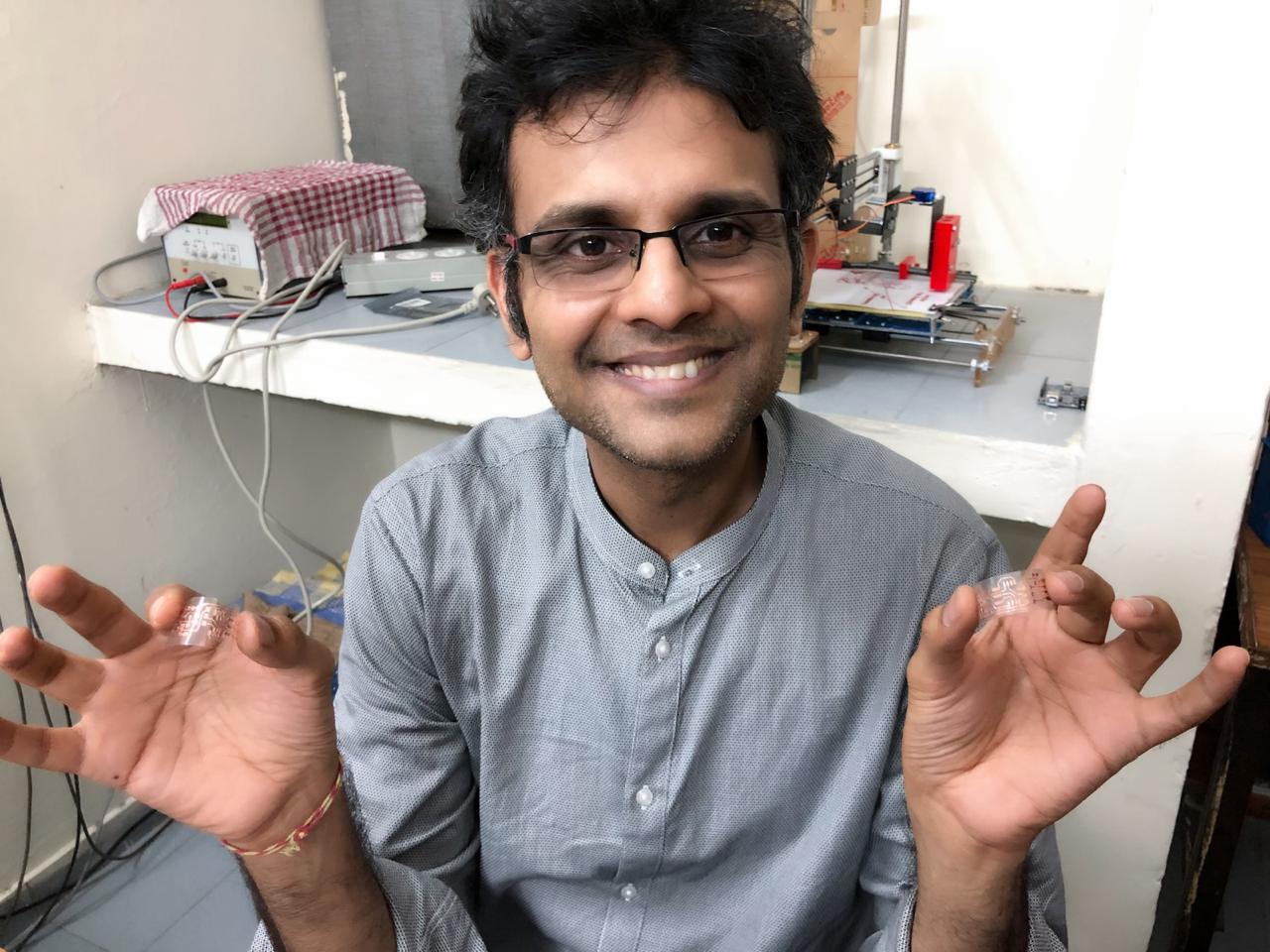
Nevertheless, the traces of flexible pcbs are indeed flexible and they can work very well with acetate film as a backing.
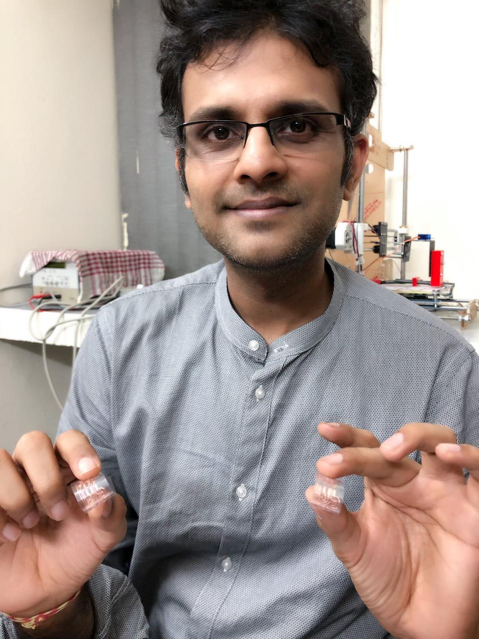
Hero shots of traces of flexible PCBs
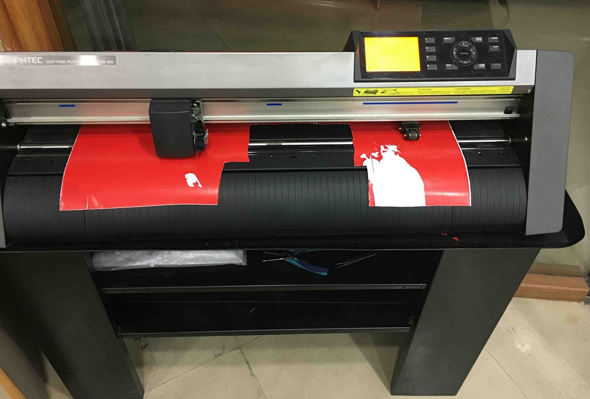
Graphtech CE6000-60
File Prep
I used Inkscape to prepare the file and exported it as a png. This png was opened in Graphtech Studio. This bitmap file was vectorized and given for cutting. I didn’t take screenshots at this time for how the png was opened in Graphtech studio. I have done this in detail for Roland GS-24 though.
Graphtech cutter setup
I went through the setup manual to understand the working of the vinyl cutter. I understood how to adjust the rollers. Once the USB cable is connected to the laptop from the vinyl cutter, we need to make sure that it is detected in the software interface. The image needs to be brought closer to the origin in the software. The knife needs to be brought at the point where the cutting needs to happen to set the origin. Then the image can be cut.
Previous work with vinyl cutter
I am sharing a previous vinyl cut text pasted with a heat press on a t-shirt in Leeds Hackspace around September 2018.

Designs difficult to work with vinyl cutter
I took an image taken from internet. It did cut alright but I don’t think it would peel off as it is not a closed image. So, it would have to be modified with a closed rectangle for it to work with the vinyl cutter.

Design Files
Group Assignment files
Download for characterizing the speed and power combination for the laser cutter for the cardboard of our thickness.
Press fit kit files
Download with parametric design in Solidworks for the press fit kit construction.
Vinyl cutter files
Download Inkscape design file with ‘fab isp’ for vinyl cutter.
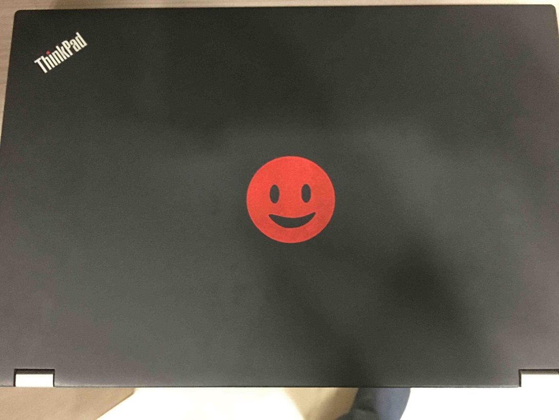
Download Inkscape design file with ‘smiley’ for vinyl cutter.
Download Inkscape design file with ‘text’ for vinyl cutter.
Download Inkscape design file with ‘image’ for vinyl cutter.

Solar powered electric bike con kit by Jay Dhariwal is licensed under a Creative Commons Attribution 4.0 International License