


Huber Girón Nieto
Electronic and Mechatronic Engineer
Contact
e-mail: huber.giron.nieto@iberopuebla.mx
phone: +52 (222) 372 3000 ext.12917
FABLAB Puebla Researcher
WEEK ASSIGNMENT:
Networking and Communications
Design and build a wired &/or wireless network connecting at least two processors
Device connections
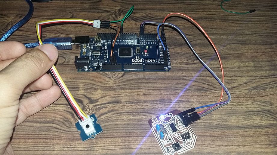
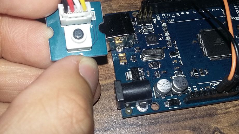
For this week activity we need to connect two processors, so we decide to use a Attiny44A micro-controller and a Arduino Mega2560 with a button and a LED in each one, so the LED connected to a processor only turn on when the other processor button is activate
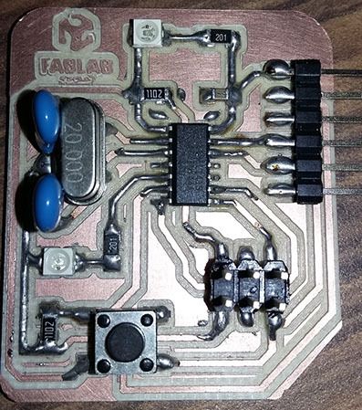
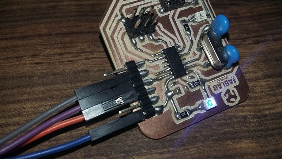
We use the attiny44A micro-controller Board made in activity six, based in Fab Academy Hello-World board:
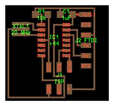
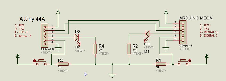
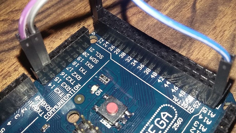
For the Network we use an Attiny44A and a Arduino Mega 2560. The schematic diagram of the Serial Network connection:
Attiny44A Code:
#include <SoftwareSerial.h>
SoftwareSerial mySerial(0, 1); // RX, TX
//Variables
int LED=8;
int BOTON=7;
int DATO=HIGH;
void setup() {
pinMode(LED, OUTPUT);
pinMode(BOTON,INPUT);
mySerial.begin(9600);
}
void loop() {
mySerial.write(digitalRead(BOTON));
delay(100);
if(mySerial.available()){
DATO=mySerial.read();
}
if(DATO==HIGH)
digitalWrite(LED,HIGH);
else
digitalWrite(LED,LOW);
}
Arduino Mega2560 Code:
//Variables
int LED=13;
int BOTON=7;
int DATO=HIGH;
void setup() {
pinMode(LED, OUTPUT);
pinMode(BOTON,INPUT);
Serial3.begin(9600);
}
void loop() {
Serial3.write(digitalRead(BOTON));
delay(110);
if(Serial3.available()){
DATO=Serial3.read();
}
if(DATO==HIGH)
digitalWrite(LED,HIGH);
else
digitalWrite(LED,LOW);
}
What protocol it uses and how it works?
This Network use a serial Network that use 2 devices connected by a TX and a RX pin connection, this serial Network uses a UART protocol to exchange data, the TX pin of one device transmit data to the RX pin from the other device, and the other device TX pin transmit data to the RX pin from the first device.
What I've learned?
The use of communication is very important to develop prototypes because it allows you to increase the processing capabilities of the prototype to use more than one electronic control device. For example, if we run out of a micro-controller outputs available, we may use the other outputs of the other device connected via network. Communications also allow us to exchange data remotely allowing multiple processors in different places but it can share information.