Redraw the echo hello-world board
I followed this tutorial for PCB design with Eagle. Eagle
includes some modules: Schematic Editor, Layout Editor, and
Autorouter.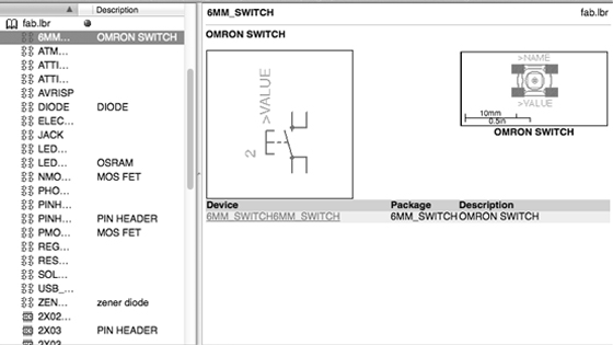
Screen capture of Eagle.
In this week assignment I added a 6mm tact switch and a chip LED on the echo hello-world board.
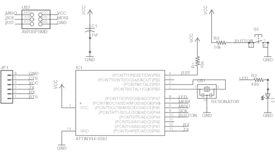
Schematic in Eagle.
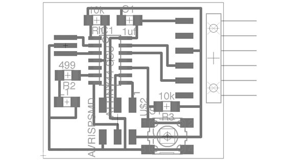
Board Layout in Eagle.
Then I exported the board layout (select the only the "Top" layer) as a png file. I opened the png file, traced the outlines, and exported as DXF file with drawing software, and subsequently imported DXF file and made NC tool paths with TypeEdit, an industrial CAD/CAM software.
I engraved the PCB board by using CNC router with a conical mill at the cutting depth of 0.1 mm and tool diameter of 0.3 mm.
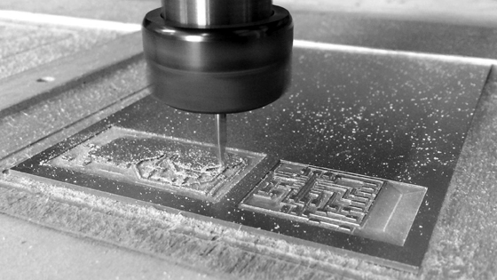
Engraving the PCB board. Modificated echo hello-world board (right).
Finally, I soldered some electronic components to the board by using HAKKO soldering iron, tweezers, flux, and lead-free solder alloy.
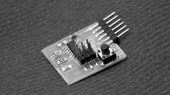
Finished board.
