Design and build a wired &/or wireless network
connecting at least two nodes
Referring to the tutorial, I tried to make Hello Serial Bus
this week. Firstly, I downloaded the trace data (PNG format) of
the boards from here and engraved the raw copper board by
using CNC router with conical mill. I made one bridge and two
node boards.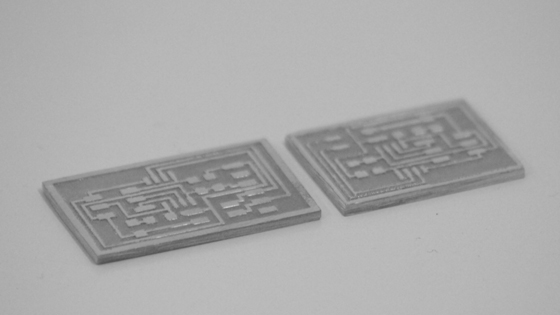
Milled circuit boards: bridge (left) and node (right).
I noticed the lack of some electronic components, and then bought some components at electronics parts shops in Osaka, Japan, and ordered some other components online at Digi-Key from the list of Fab Lab Inventory. The components were soldered on the boards as shown in the figure below.
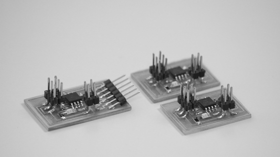
Boards I made: bridge (left) and two nodes (right).
Next, I downloaded and modified the C code. Each node (including bridge) needs to have a different ID number. We therefore need to change the line below in the hello.bus.45.c code. In my case, I defined the bride as '0', one node as '1', and another node as '2'.
#define node_id '0'
Then, I connected the FTDI header to the bridge boards, and made the serial connection between the boards with a 4-pin serial cable.
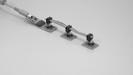
Serial connection.
Once the boards are flashed, we can communicate with the network by typing the defined numbers in the "Serial Monitor" of Arduino IDE. When I typed the number into the box, the LEDs on all the boards lighted up once, and the LED on the board with the number I typed lighted up again.
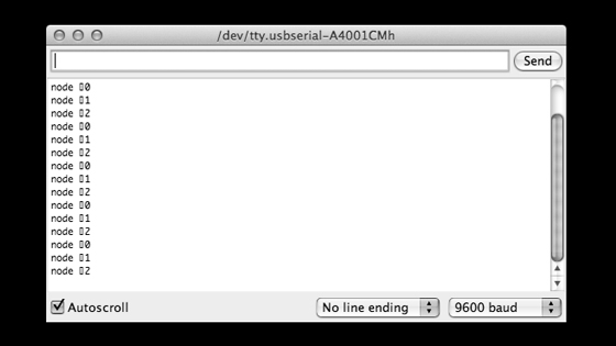
Serial Monitar.
