

My final project
In this webpage you will see the evolution of my final project. If you want more detailed information of some of the topics, you can go to the different assignments of this semester.
Project index
- Project slide summary.
- Applications and implications.
- Mechanical design. Structure design.
- Electronic design.
- System layout.
- Programming the boards.
- Programming the computer application.
- Assembling all components.
- Testing the system.
- Conclusions and... next steps?.
Project slide summary
|
|
Applications and implications of my final project
What it will do?
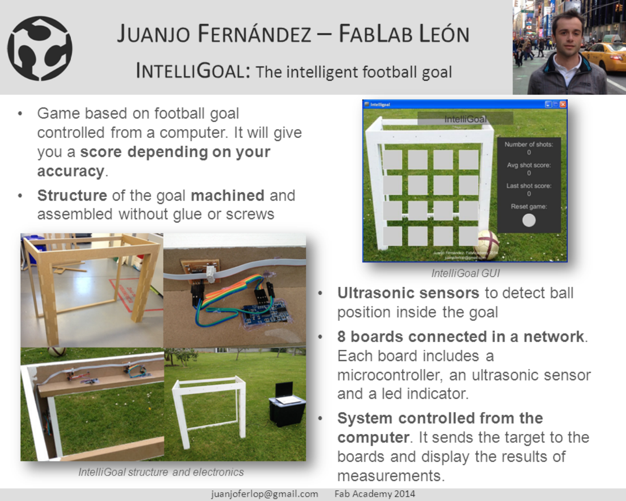
My final project will be the IntelliGoal as I called it. It will be a game based on a football goal controlled from a computer. With an application created for the computer, the user will select a position of the goal. Some indicators will be displayed in the goal to show where to aim at, and after the shoot, the accuracy of the shooter will be displayed in the computer application.
In the future I would like to include different games for the goal, with different users and so on, instead of a single select position and calculate accuracy.
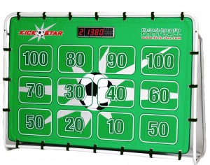
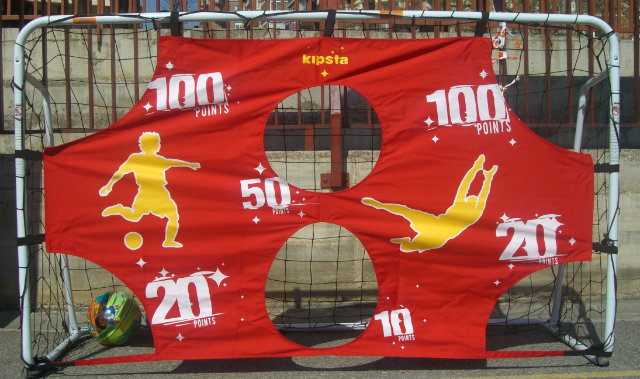
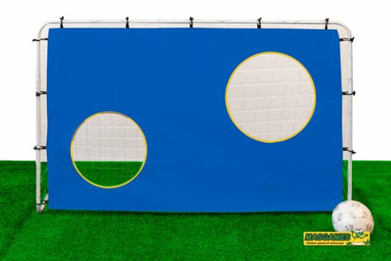
Who's done that beforehand?
At the beginning of the semester I looked in internet to find if there was something similar, and I didn't found anything exact. I have found some similar things, but none automatized as I wanted it to be.
|
|
|
|
What materials and components will be required?
The materials needed will be basically divided into two: the materials needed for the goal structure and the electronics for the automatizations.
Goal structure: It is needed a MDF board to mill the goal parts.
Electronics: Depending on the size of the goal, several sensor will be needed (one to control each sensor). The design of the sensor was done in Networking and communications assignment. The list of components for each board are:
- 1 x Attiny84 microcontroller
- 1 x HC-SR04 ultrasonic sensor
- 1 x LED diode
- 1 x 500 ohm resistor
- 1 x 10 kohm resistor
- 1 x 10 uF capacitor
- 2 x header pin connector
- 2 x socket pin connector
Where they will come from?
MDF come from a local vendor that we have here really near to the FabLab.
The electronics come from DigiKey, Mouser and similar online electronics sellers.
How much it will cost?
The cost of the MDF board is less than 20 €.
The cost of each electronic board is less than 10€, as the more expensive part is the microcontroller (less than 2€) and the ultrasonic sensor (less than 3€). I expect to use about 8 boards, so the total cost of the electronics will be below 80€.
Considering all together, the total cost of the goal will be less than 100€.
What parts and systems will be made?
Everything!!!. The goal structure will be made with the computer controlled machine, and the electronics custom designed. Only the ultrasonic sensor will be purchased instead of made, but it is even more cheap!!
What processes will be used?
- Computer aided design to design the goal structure
- Electronics production & electronics design for the boards
- Computer-controlled machining to create the goal structure
- Embedded programming for the code of the sensors
- Input devices (to measure from ultrasonic sensor) and output devices (the display of the position to aim at
- Networking and communications, as about 8 nodes will be used
- Interface and application programming, for the computer application
How it will be evaluated?
I am sure I will have the goal working for that date, so the evaluation will be to test it in different conditions. Select from the computer different positions, and some times aim at it and some times not. If it is able to detect always the accuracy and the ball position, I consider it will be enough for this semester.
Mechanical design. Structure design
During the assignment of computed controlled machining I designed a first prototype of the goal structure:
|
|
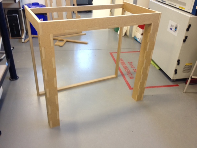
However, as it usually happens with a first prototype, included some errors. In this case, it was two important errors that must be solved for the final design:
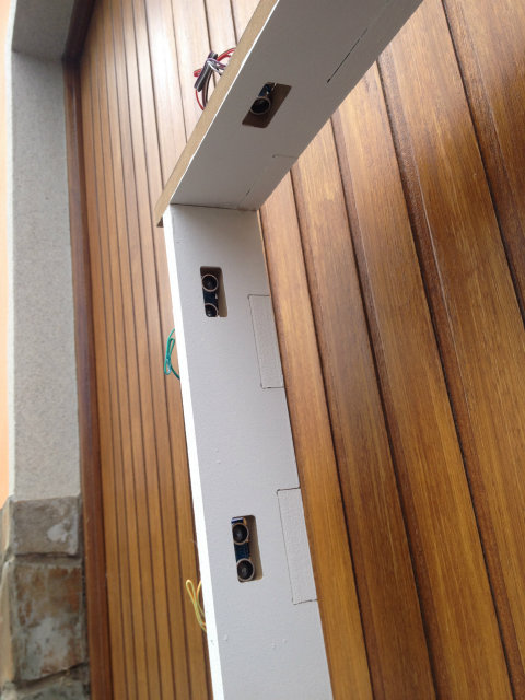
Mistake 1: The assemble of the inner part of the upper part of the goal was impossible. I needed to eliminate the flaps I had put in the upper part. Luckily, it was possible to be done with a hand saw instead of redesigning and making again the part.
Mistake 2: I made the holes for the sensors placement in the outer side of the goal and not in the inner. This will not allow the sensors to detect the position of the ball as it is passing through the goal line. I will need to modify the design and make again this parts.
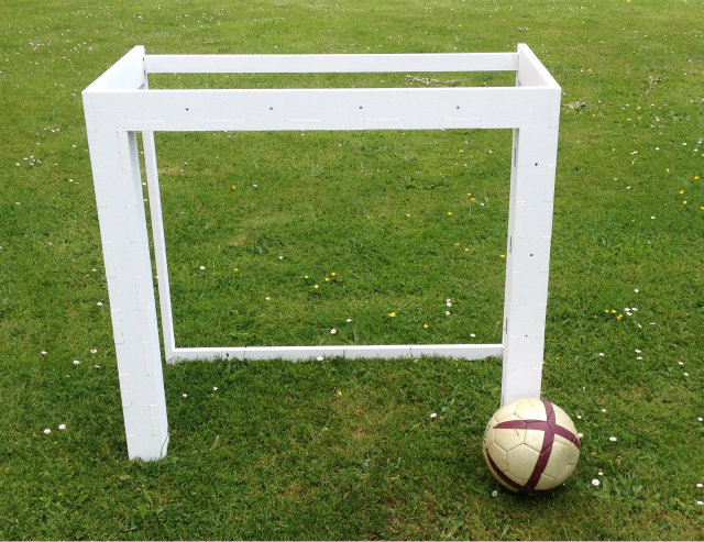
After being identified, a new design of the goal was created with OpenScad and built again with a new MDF board. You can download the design files here.
If you pay attention, the size of the goal is significantly smaller than a traditional football goal. I decided to do it in this size mainly for two reasons:
- The complexity it is the same. It is a matter of use 8 or 16 sensors, but all the components are the same. In fact, parametric design in OpenScad will allow to scale it very fast.
- I want to take it to my home at the end of FabAcademy. If it is too big, I will need a truck to take it.
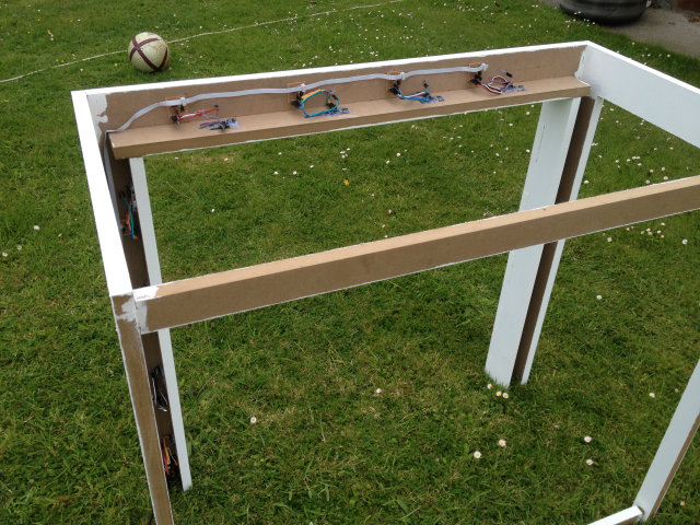
It is important to remark that the goal was assembled without using screws, glue or similar to keep them together, and the structure is very stable and rigid.
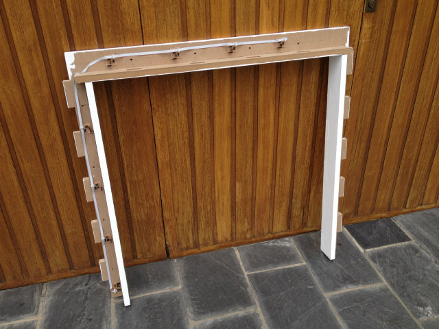
Once the structure was machined and assembled, I painted it to get a better appearance:
|
|
Electronic design
After the design of the mechanical and structural part, the next step is to design and build the electronics that will control it.
Due to the size of the goal and the typical size of a football ball, I calculate that I need 8 sensors to cover the whole goal: 4 in the top and 4 in the side posts. That brought to me the first doubt: use one electronic board (and in consequence one microcontroller) with a lot of inputs and outputs, or design several and simpler boards communicated by themselves? Finally, I decided by the second option.
To measure and detect the ball I will use the HC-SR04 ultrasonic sensor. I already used it in the input devices assignment with very good results: it offers more accuracy than I will need, it is very fast and cheap.
All the boards will be attached to the same bus and connected to the computer, and the core of each one will be an Atmel Attiny84. I went to the Attiny84 instead of the typical Attiny44 used during FabAcademy because the cost difference is very small and I needed those 4kB of program memory extra.
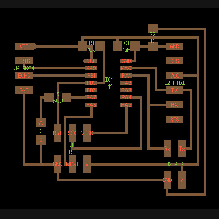
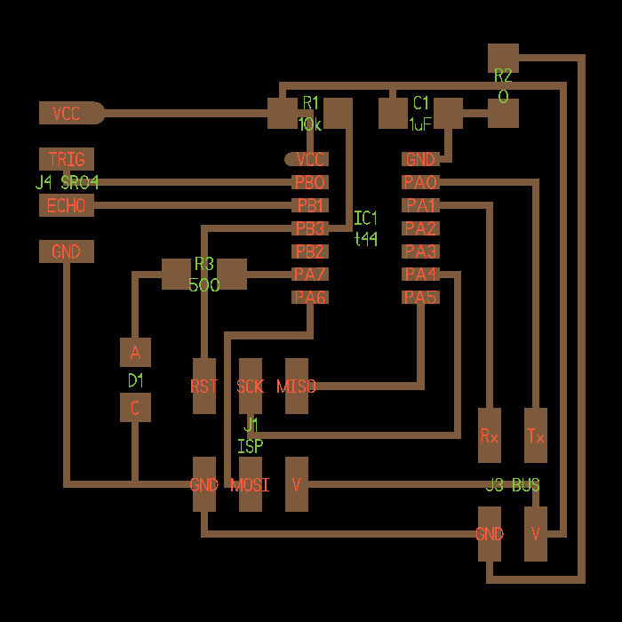
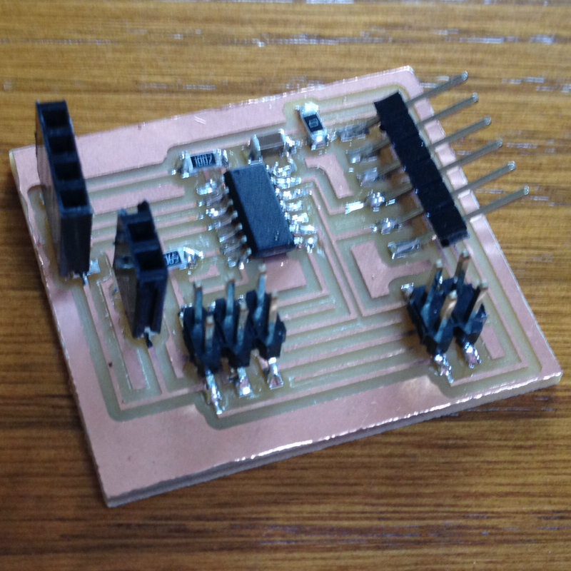
The boards were designed with Kokopelli, and you can download here the bridge design and the node design.
|
Bridge kokopelli design |
Node kokopelli design |
|
|
|
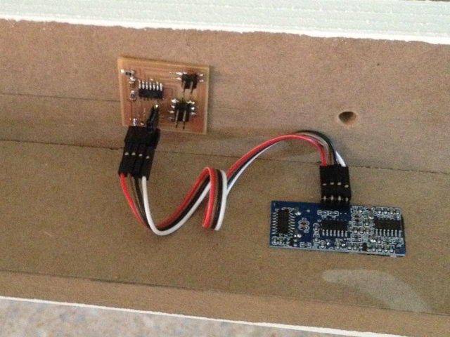
|
Bridge board assembled |
Node board assembled |
|
|
|

|
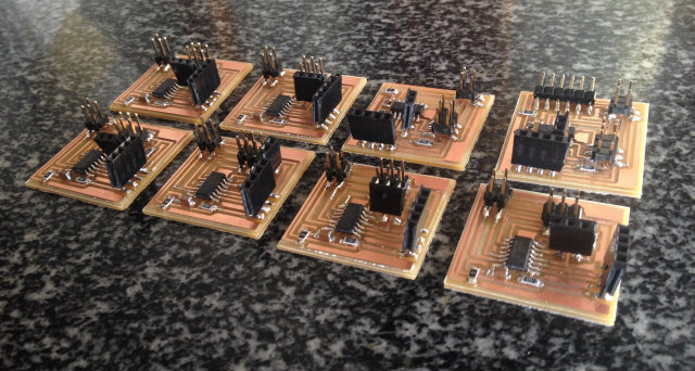
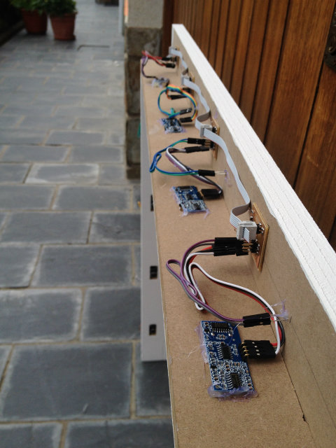
All the boards needed for the goal |
|
|
System layout
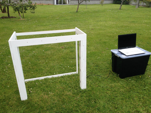
Here you can find the project layout. It includes the goal structure, a computer to control the goal and 8 sensors: 4 in the side post and 4 in the top post. The eight sensors and the computer are connected with a bus.
|
|
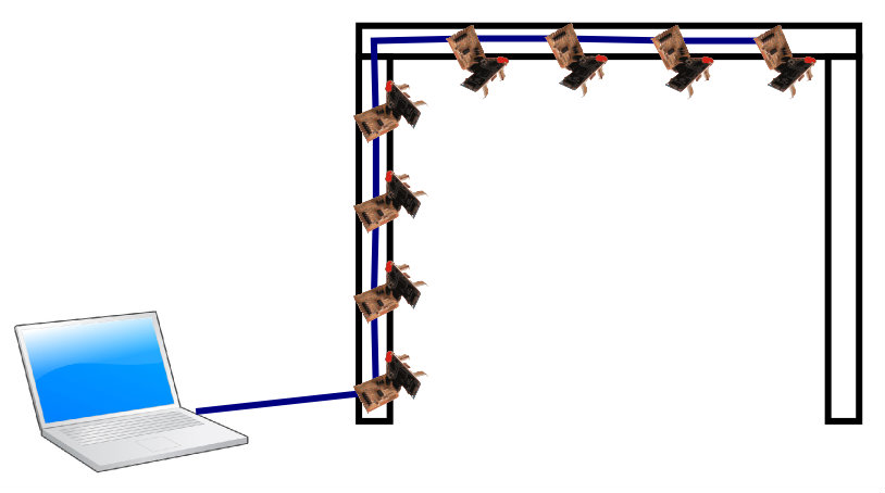
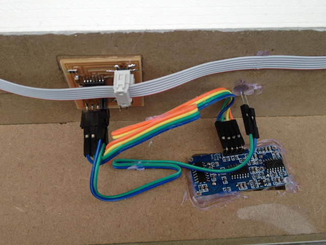
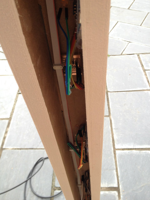
The bus connecting the eight nodes is a 6 cond flat ribbon cable, although really only 4 are used for Vcc, GND, data from nodes to computer and data from computer to nodes. The connection of the cable to the nodes is irrelevant, once all the connectores are plugged in the same way.
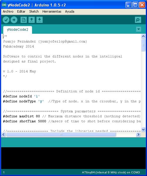
Programming the boards
Before assembling all the boards to the goal, I did the programming: It is easier to make it with the boards still not in the goal, so you don't need to be close to it.
To program them I will use the Arduino IDE, and the algorithm to be implemented is an infinite loop.
- Wait until board id received.
- Switch on led to indicate position.
- Measure distance while distance measured is the same (no ball detected).
- Send the distance through the bus with the board id.
- Switch off the led and go back to the beginning.
|
|
When programming the boards and using several of them, I faced to different problems I needed to solve. Here there is an explanation:
- Interference of ultrasonic sensors: When you have more than one identical ultrasonic sensor working at a time, you will have interferences. I needed to synchronize the vertical and horizontal sensors in order to avoid these interferences.
- Collision of data in the bus: Both sensors, vertical and horizontal, will detect the ball almost at the same moment. If both send the data at the same time through the bus, a collision happens and wrong data is received. It was delayed the data sent by horizontal nodes to avoid it.
Here you can download the code for horizontal and vertical nodes.
Programming the computer application
The idea I have is to control the goal from a computer application. Through an interface you will select a position of the goal, and depending on your accuracy you will get some points.
The program was developed in Processing, and the algorithm implemented is:
- Wait until a button is pressed.
- Read the position button pressed, and send to the nodes the horizontal and vertical id.
- Wait until the answer of measurement is received.
- Once the answer is received: calculate the accuracy, update the statistics and the screen.
- Wait until a button is pressed again.
You can download the source code or the full project with all the associated files.
|
|
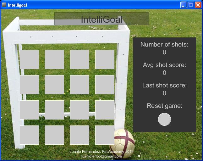
How it works? In the application you have 16 buttons, which correspond to the 16 positions you can aim at. Once you have selected one, it will be indicated in the goal with the led indicators, and you have 5 seconds to shot at that position.
Once you have shot, the system will give you an score depending on your accuracy which will be displayed in the screen, and you have some statistics about your performance. You can clear all the historical data with the reset button at any moment you want.
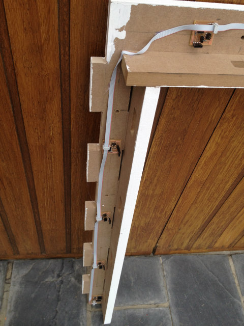
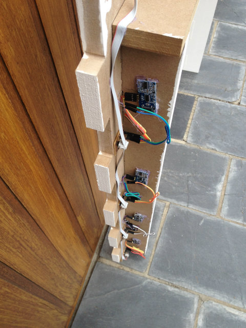
Assembling all components
All the parts of the project are built, so it is the moment to put them all together and find how it works. To put together the electronics with the structure, I used a silicon gun. In the pictures below you can see all the steps.
|
|
|
|
|
|
|
|
|
|
|
|
|
|
|
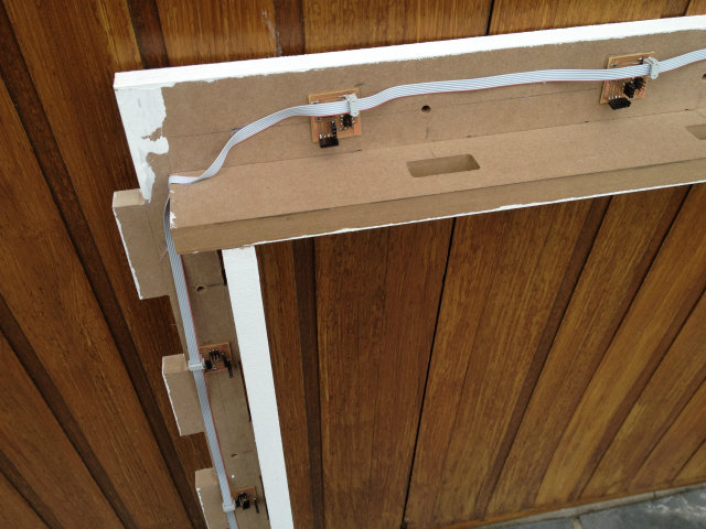
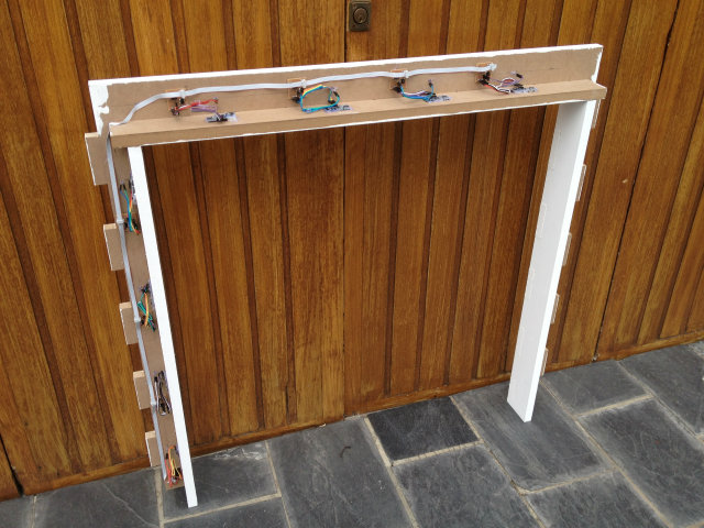
And now the goal fully assembled:
|
|
|
|
Testing the system
The development and assembling of the goal is over. After some days of hard work in order to see if everything was right and fixing some bugs, it is the time to test the goal and see its performance. Here you can find some demo videos.
In videos one and two, the ball is passed through the goal with the hand. The idea is to have very good accuracy with the shoot and verify that the goal is measuring properly. In the last video, the ball is kicked, and now the accuracy is not so big, but it verifies that the goal is able to detect a ball kicked passing through it.
Demo 1, testing the different scoring depending on the accuracy. Always the same target.
Demo 2, modifying the target, to verify that all sensors are working properly.
Demo 3, it is time to kick the ball. Different shots with different levels of accuracy, to see how the system is able to detect a football hit and also the score depends on the accuracy.
Conclusions and... next steps?
FabAcademy 2014 is over, and also my final project. During the development of this project I learned and realized about a lot of new things I want to summarize here so it can be useful to everybody:
- Computer controlled machining was a good option to create the goal structure. All the parts assembled in a perfect way and the final structure was very robust. Although the sensors were properly attached to the goal with the silicon gun, it could be improved with a custom piece designed for that.
- Ultrasonic sensors are very cheap, easy to use and deliver very good performance. On the other hand, when you want to use more than one, it is very hard to do. Yo need to perfectly synchronize them to avoid interferences. Also the pointing of the sensor is very critical as you can have fake echo's perturbing your measurement.
- When you are using more than 2 nodes, USART communication is not a good idea. You must switch the Tx pin of the nodes to tristate when you are not transmitting, and you must be careful not two sensors are transmitting at a time to avoid collisions. If I start again my project, I am sure I would use a different one (maybe I2C).
- I did the computer application with Processing as I wanted to test anything new. However, Processing did not convince me at all. I think it could be good for beginners, but for people who are used to software development there are better options.
You can also download a package with all the files created in the project here.
Next Steps?
At this moment my project is finished, and I have covered everything I fixed myself as objectives, so I consider it a success. Anyway, in the future I would like to implement some new functionalities to make it more complete and entertaining. Some of these are:
- Improve the accuracy calculator. It is working pretty well, but from time to time it give some weird scores.
- Create mini-games with different players to challenge your friends.
- Make it autonomous, with no need of computer. I think some buttons and LCD display will be needed.
Anyway, now that we don't have a deadline pushing us, let's see when they are done...

This work is licensed under a Creative
Commons Attribution-NonCommercial 4.0 International License.