

Week 10. Input devices
The assignment for this week is to measure something: add a sensor to a microcontroller board that we have designed and read it. In my final project I will have some ultrasound sensors, so I will take advantage of the assignment of this week to start to play with it.
Designing and building the board
The first step it is of course to design and build the board with the microcontroller and the input sensor. As I said, I will take advantage of the assigment of this week to measure distance with an ultrasound sensor that I will use in my final project to measure the position of the ball in the goal.
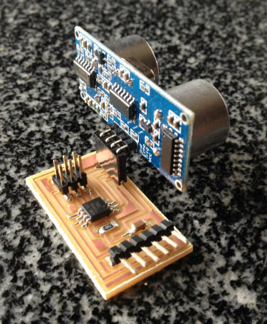
I decided to use a ATtiny45 Atmel microcontroller to measure the input signal produced by the HC-SR04 ultrasonic ranging module. I selected this ultrasonic sensor because it is very low cost (less than 3$), it has a measurement range of up to 4m and it seems quite easy to use.
|
|
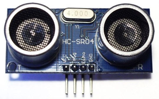
In the datasheet of the sensor there is a detail of the connections needed: two microcontroller pins are needed, one to generate the signal and a second one to measure the echo.
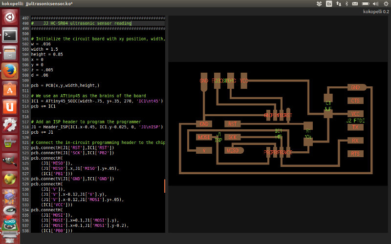
To design the board, as I felt quite comfortable during electronics design assignment with kokopelli I decided to go on with it. This time I needed to create the footprint for the connector of the ultrasonic sensor, and I also edited the footprint of the ATtiny45, that although it was available in the library, the label of the pins was not correct. You could download the file here.
|
|
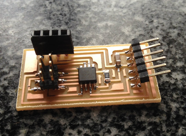
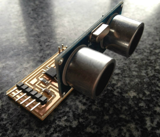
Then it was only remaining to mill the board and assemble it before starting with the tests.
|
|
|
|
Programming the board
As I decided to do my own board with a different sensor than the examples available, the code files in the repository were not valid for me. What I did was to take embedded programming week software as an example, and make the opportune modifications to read the ultrasonic sensor.
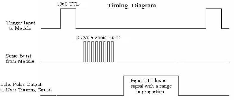
In the figure below you can see the timing diagram extracted from the datasheet. To measure it is needed to apply a burst of 8 pulses in the Trig pin (attached to PB3 pin of the microcontroller) and observe in the Echo pin (PB4) the time elapsed until the reflected signal is received.
|
|
You can find below the Arduino code I made after some tests, and you can download it here.
|
|
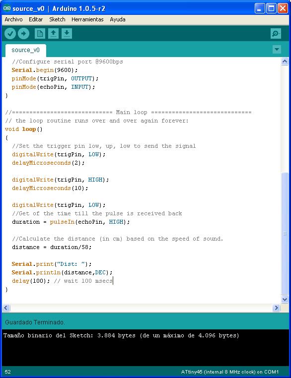
The software is taking 10 measurement each second, converting them into cm, and sending the information through the serial port. This information can be read by the computer in the serial COM port.
Testing the software developed
In order to test if my board was properly running or not, I opened a hyperterminal in Windows and I made several tests to see if the sensor was successfully measuring.
In the video below you can see the sensor measuring. It is a first approach, but the results are very promising. There are some weird measurements from time to time, but I think it will be quite easy to solve with a bit of signal processing.