

Week 13. Networking and communications
Week 13 of the FabAcademy is the moment to start to communicate different electronic boards, so the assignment is to design and build a network connecting several nodes.
This skill also some of the ones learned during the FabAcademy that I will use in my final project, so again I will take advantage of this week to develop something that I will use in the future.
Designing and assembling the boards
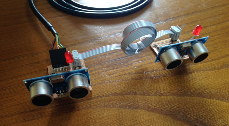
This week I will do the boards to be used in my final project. The idea is that each board will include an ultrasonic sensor and a led: the ultrasonic sensor will measure the position of the ball, and the led will indicate the target.
At each moment, only one horizontal and one vertical boards will be working at a time. The definition of the actives boards will be send by the computer, and when the ball is detected, both sensors will send back to the computer the measurement.
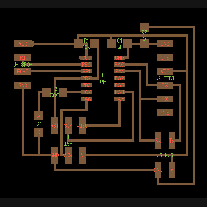
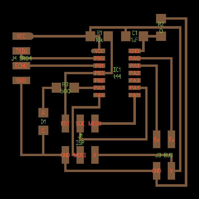
Starting from Neil's examples, I decided to make one bridge board, that have the interface with the computer, and several node boards which are identical except for the computer interface.
Due to the features of my boards, the layout of the network connection showed on Neil examples makes me very difficult to make the paths, so I decided to modify it. I swapped the position of Tx and Rx pins, but taking care of doing it in all the boards.
|
Bridge kokopelli design |
Node kokopelli design |
|
|
|
|
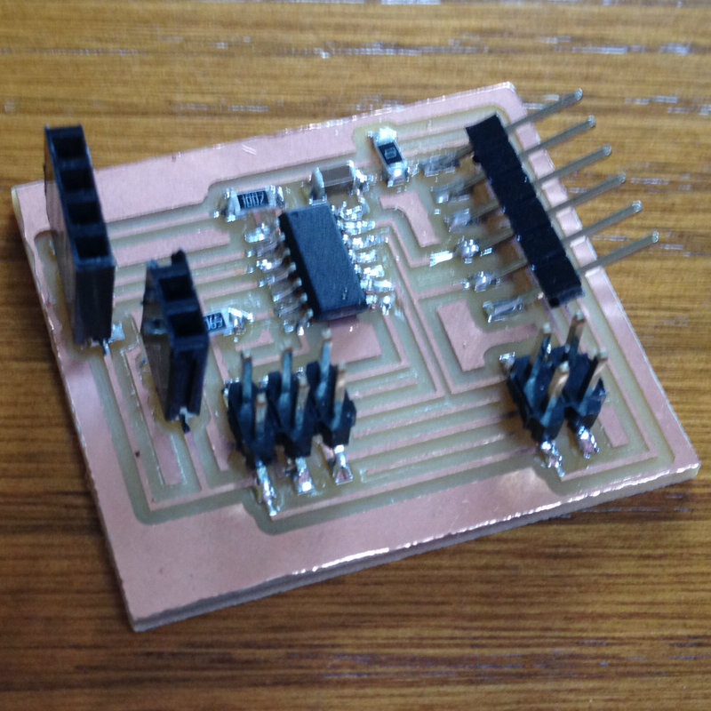
Bridge board assembled |
Node board assembled |
|
|
|

|
Boards connected |
|
|
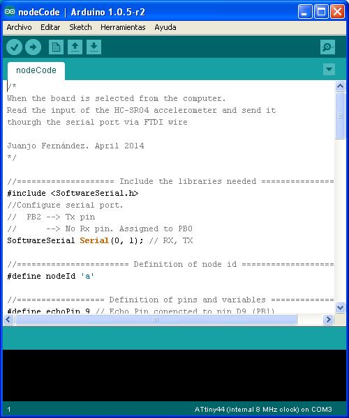
Developing the software
The code programmed in each of the elements of the network will have implemented the next algorithm:
- Check what character is received from the network.
- If the character matches the defined node ID:
- Switch on the led
- Measure distance with ultrasonic sensor
- Send measured distance with node id to the computer
- Switch off the led and go back to default status
When I did the first tests with only one board, it worked fine. Anyway, when I connected a second board, although the led was flashing (meaning the data was received), no information was received back in the computer. At that moment I remembered something that Neil explained in the lesson: When you are not transmitting, set the output pin to tristate to release the channel. I thought that Arduino library was doing that by itself, but it doesn't. I modified it and did it manually and then it worked fine.
Serial.print("Sensor: ");
Serial.print(nodeId);
Serial.print(" Dist: ");
Serial.println(distance);
pinMode(TxPin, INPUT);
You can find the Arduino code developed here.
|
|
Testing the software
In the video below you can see some tests done with the network created. When from the computer sends the id of any of the nodes, this one selected is flashing the led and sending back the distance measured.