
Week 7. Computer controlled machining
The assignment for this week is make something big. As for my final project I planned to do something big, I will take the opportunity this week to design and build the structure of my goal.
Designing the goal
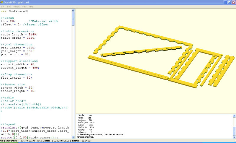
The first step before making the goal is of course to design it. To design it I used OpenSCAD, as it will allow you to modify easily the design thanks to the parameters if the parts do not fit well.
After looking at different project from previous year to get ideas of how to assemble the parts, I came up with a first design of my goal.
|
|
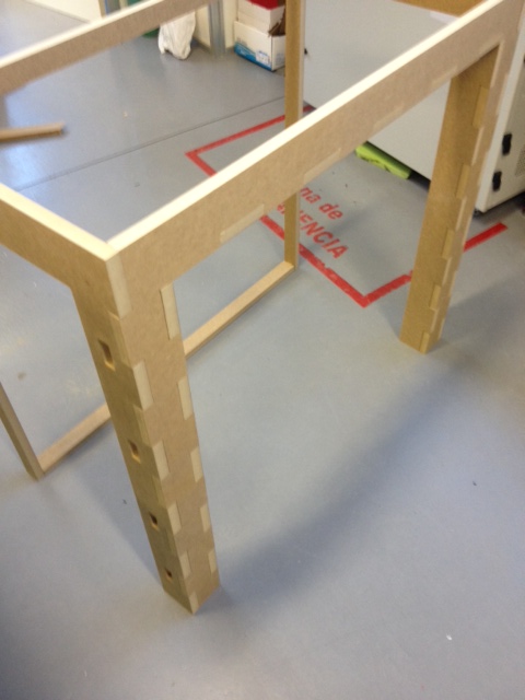
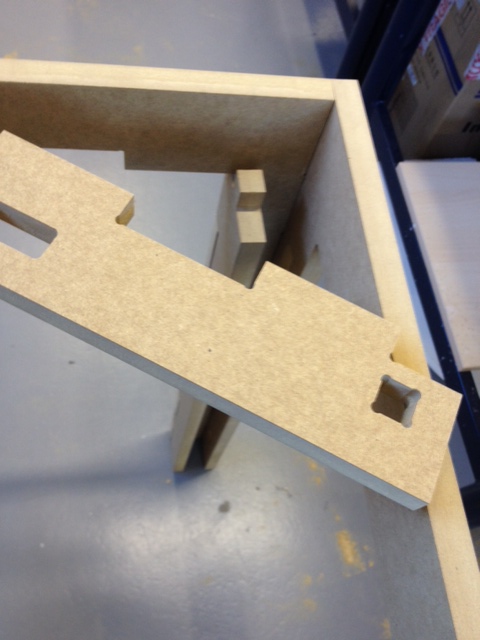
For the assembling of the pieces I thought about many options, but finally I used finger tenon joints, as it seems to me it would give good consistency to the design. You can find different wood joints in this interesting webpage.
Machining the goal
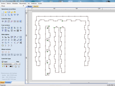
The CNC milling machine available at FabLab León is a Tec-cam 500, with a bed size of 2440 x 1220 mm. The software used to export the files to this machine and define the different trayectories, estrategies and so on is VCarve . The goal will be machined and built in wood.
The workflow of VCarve is the following:
- Create a new file, defining the dimensions of the board you are going to use, and import your design in .dxf format.
- Select the parts of the design you want to make, and create a new trajectory for them.
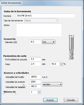
- Define the end mill you will use. In my case, it was a 6mm wood end mill, at 24.000 rpm and 2000 mm/min of speed.
- Create the trajectory and verify if it is coherent. If some of the lines are not properly closed, you will see some weird trajectories.
- Export the .tap file to a usb drive that later will be used in the milling machine.
|
|
|
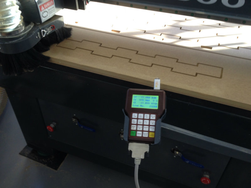
Now, it is the moment to go to the machine with your design. It is very important to be careful with this machine, as it could be very dangerous. The workflow is:
- Set the x origin and y origin of the machine depending on your board.
- Turn on the vacuum, and verify if the board is properly fixed to the deb.
- Calibrate z origin with the calibrated block.
- Insert the usb drive with your design and run it.
- Turn on the extractor to avoid excessive accumulation of sawdust.
- Pay attention especially to the first moments, and never leave the machine alone.
|
|
|
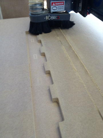
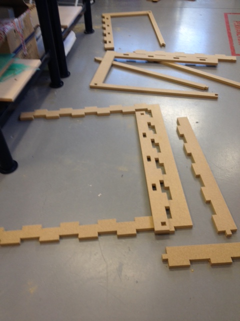
I decided not to do all the parts at a time, so I could modify the design if a mistake is detected in advance. I did it in three steps, and I finally got all the parts of the goal.
|
|
Assembling the goal
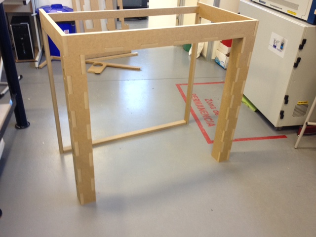
With all the parts ready, it was only remaining to assemble them. The assembly of the parts was even more robust than I thought, but I discover two mistakes I made in the design...
Mistake 1: The assemble of the inner part of the upper part of the goal was impossible. I needed to eliminate the flaps I had put in the upper part. Luckily, it was possible to be done with a hand saw instead of redesigning and making again the part.
|
|
Mistake 2: I made the holes for the sensors placement in the outer side of the goal and not in the inner. This will not allow the sensors to detect the position of the ball as it is passing through the goal line. I will need to modify the design and make again this parts.
Apart from the mistakes, the designing and manufacturing of the goal was a success for me. I was expecting to find more problems and need to iterate the design more times, but I think it is quite consistent for my final project.
|
|
|