

Week 12. Output devices
Two weeks ago we did the input devices assignment, and now it is time to do output. The assignment for this week is to design a board with an output device and program it to do something.
Designing the board
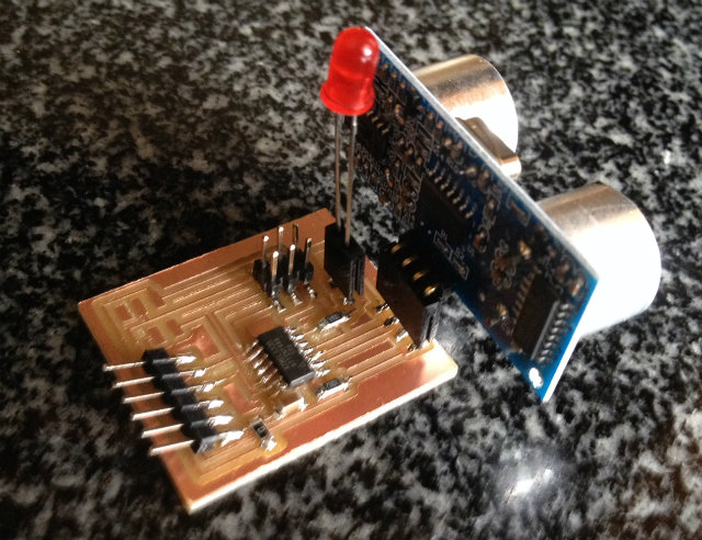
Continuing what I did in input devices assignment, I want to implement an indicator to show in the board by itself how far or close is an object to the sensor. It will be a led that will flash at different frequencies, depending on the distance to the object.
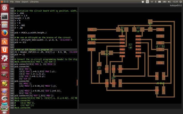
To design the board, as I did in previous weeks, I used Kokopelli. Although the board will not interact with the computer, I will include a FTDI connector to power the board. I am also using an Attiny44 instead of the Attiny45 as I need more pins to connect all the components. You can download the Kokopelli file here.
|
|
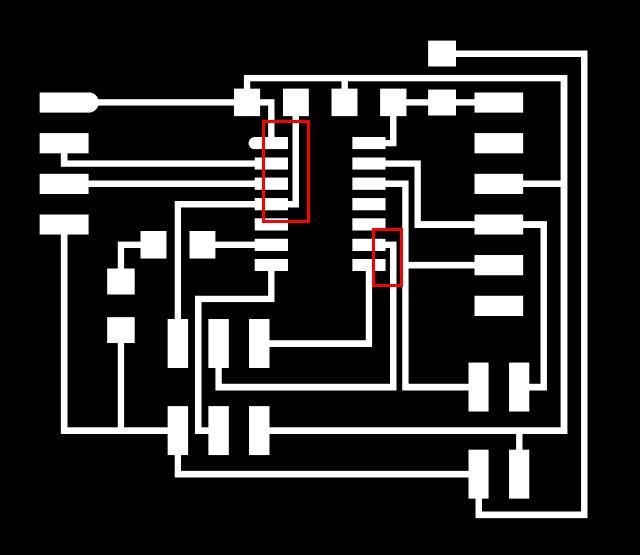
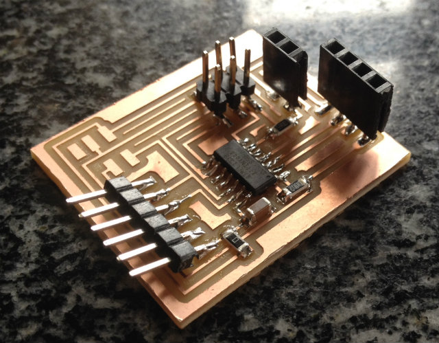
Then I milled the board, and when it was ready to assemble the components I realized and error in the design. Kokopelli does not include a tool to check the minimum space between paths (as for example Eagle does), so some of the paths were to close and it was not possible for the mill to properly do it.
|
|
|
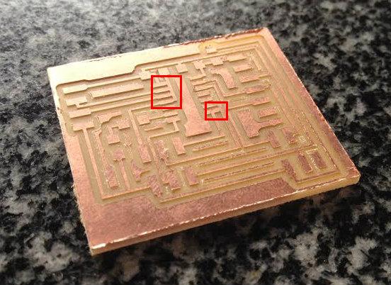
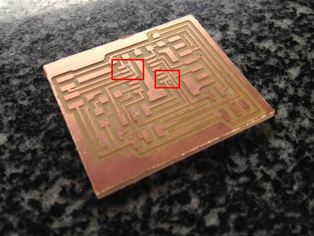
To solve it, instead of design and mill the board again, I tried to cut the errors with a razor. The results were quite good.
|
|
And finally it was only remaining to assemble the board. To connect the input and output devices, instead of attach them directly to the board, I added two connectors so I can reutilize them.
|
|
|
Programming the board
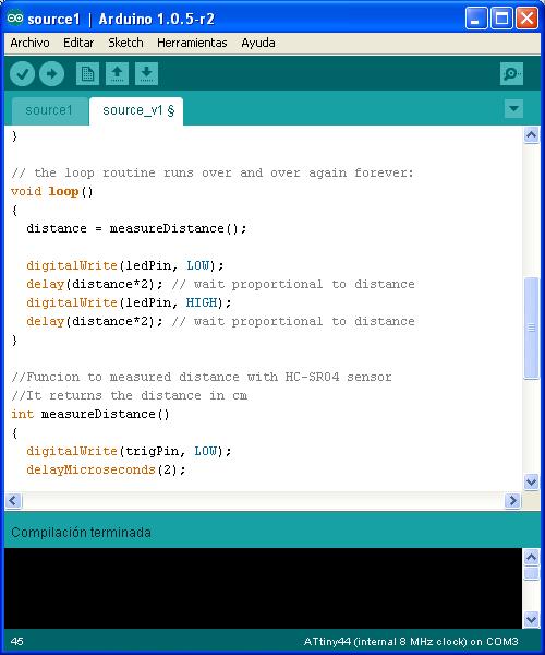
To program the board I will continue using Arduino IDE. Starting with the software I developed during input devices week, I made some modifications to instead of sending the value to the computer, flash the led. The new software developed can be downloaded here.
|
|
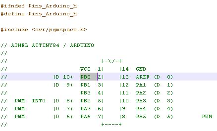
This time I used an Attiny44 instead of the Attiny45 I used in previous weeks. When configuring the I/O ports in Arduino, I realized that the Attiny44 has PORTA and PORTB pins, so I needed to identify the port number assigned by Arduino to each one. This values are assigned in the hardware definition, in the folder Arduino\hardware\attiny\variants\tiny14\pins_arduino.h.
|
|
When programming the board, I had the same problem detected in previous weeks: I got an error and I was not able to contact with the target device to program it. After verifying it with a multimeter, I went back to an old board, and the same problem was present... I was a bit upset when I realized the issue with the ISP cable, so I decided to make a new one... and it worked!! The old cable seems to have some contacts damaged, and it was not possible to use it.
I also realized that the Arduino IDE is too heavy... with a very simple program, it is using more than 1.5ks of program flash memory... I think it is a bad idea to implement something complex in a small microcontroller using Arduino... so I will evaluate in the future to migrate to C code to develop my final project.
Testing the software developed
The software was uploaded to the microcontroller, and in the video below you can see the system working. As you can see, the led is flashing, and as the object comes closer to the sensor, the frequency is higher.