
Week 4. Electronics production
The fourth week of the FabAcademy was the first one related with electronics. After some basic concepts about PCB fabrication and assembling, it was the moment to build our first PCB: the FabISP in-circuit programmer we will use later to program our circuits.
From design to PCB
During the lesson, three different alternatives to build the ISP were presented, and I decided to build Andy's design because the fact of not needing a USB cable was atractive to me.
After selecting the design, it was time to create it with the Roland Modela MDX-20 available at FabLab Leon. Before building my PCB, Nuria taught me the basic concepts of the Modela and the workflow, and I made some tests with old mills.
At FabLab Leon the modela is controlled by a computer with Ubuntu and Fab Modules version 8/16/12. In this software it is where you load the files to be build and you define the main parameters the machine is going to use in the milling process.
The main worflow is:
- Open Fab Modules, select .png as input format and Roland Modela as process, and clic on make_png_rml button
- Load the .png file of the paths you want to create.
- Select the appropiate milling tool: 1/64 for mill trace and 1/32 to cut the board.
- Verify the selected parameters, and modify any you consider necessary.
- Create the .path file by pressing on make .path button.
- Put in the Modela the mill you are going to use. Insert it more than necessary to make later on the z-axis adjustment.
- Ask the head to go to initial position by pressing on move to xmin, ymin button.
- Use the up and down buttons to put the mill close to the surface to be milled.
- Loose the mill contact and carefully let it touch the surface. Then tight again the screw.
- Make the .rml file and send it to the machine.
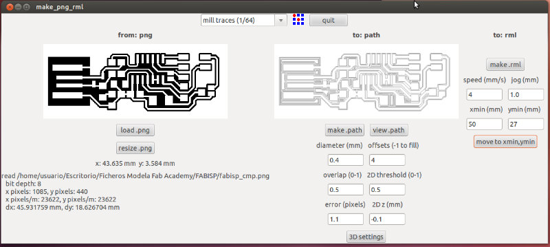
Once I was used to the workflow and I felt confident enough to play with new mills, I mounted new mills in the Modela to start to build my own FabISP. It is important to make the paths before cutting the board, so the board will not move. I configure the Fab Modules with the following parameters and I did the workflow mentioned above.
|
|
As I am sure that my poor soldering skills will make me make some mistakes, I decided to build two boards, so I will have a backup one.
|
|
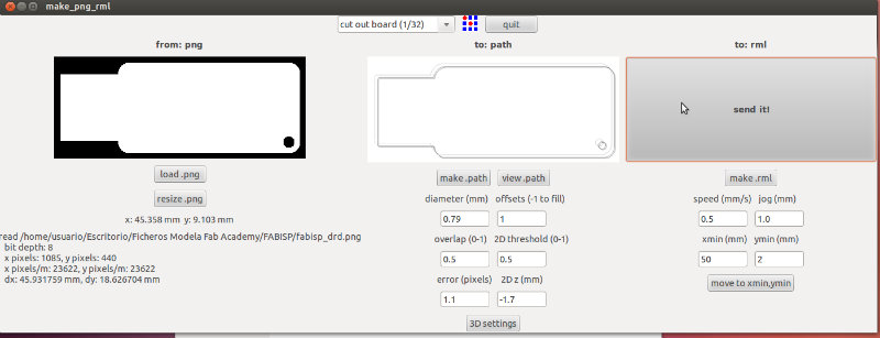
Once the traces are ok, we are ready to cut the board to have the definitive design ready. It is time to start again the workflow but with a wider mill (1/32). At this moment I observe some particularity with the Modela and FabModules: if you keep open the Fab Modules, the machine will remember the origin position, but if you close and reopen the Fab Modules, you will need to do again the origin calibration.
The parameters used in the Fab Modules to cut the board are:
|
|
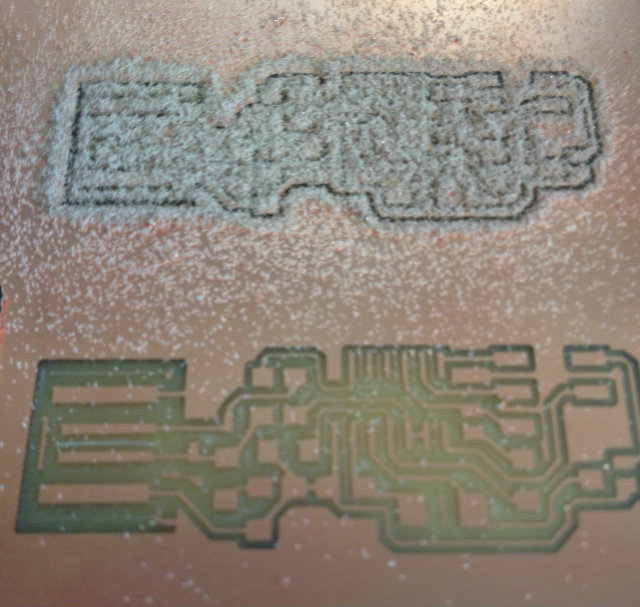
And you can see here the machine working and cutting the board, and also the two FabISP built
|
|
|
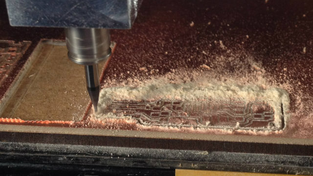
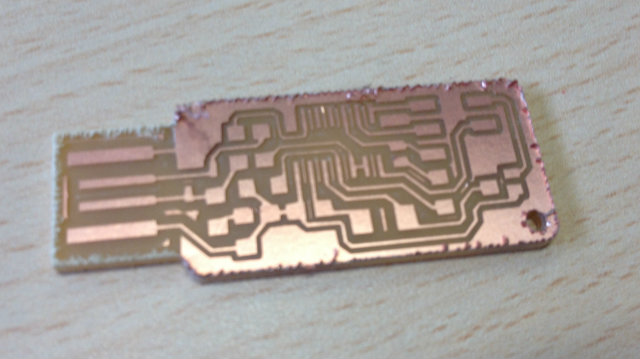
As you can see, in the boundary of the FabISP there are some shards on the edge, so it is important to sharp them to avoid some silly cuts.
Soldering the components
The moment to solder the components has arrived. I am not very good at manual activities, so I am a bit afraid about it. Before starting to solder, I decided to come back to Neil and Nuria advices. Here are the list:
- Before starting to sold, wash up the board to clean impurities.
- Start to sold the smaller components (Resistors, diodes, capacitors) that will not disturb you when you are soldering other components.
- Heat up both sides: the copper on the board and the pad of the component.
- For two pads components:
- Put a bit of tin on the board in the position of one of the pads.
- Put the component on the final position and heat up the pad with the tin below.
- Sold the second pad.
- Come back to the first pad to put some extra tin on the top.
Although I tried to do it as careful as possible, the first approach was not a success. I needed to take out a component that was already placed, and I take some of the copper path with it. Obviously, I had to discard that board and try it with the second one.
|
|
|
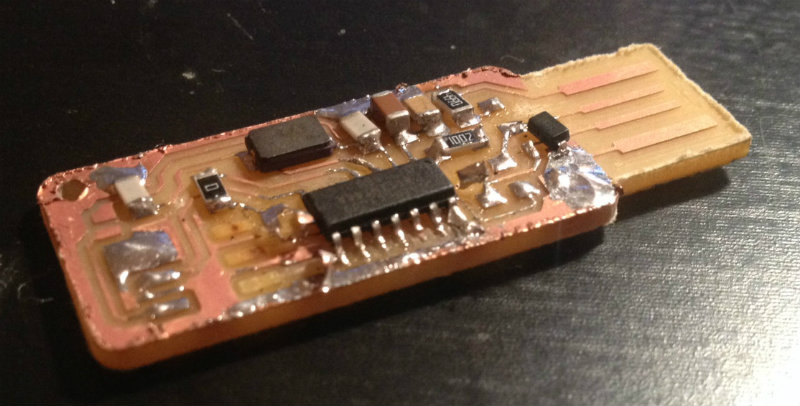
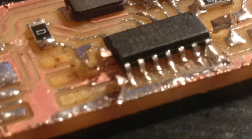
As Neil said during the lesson this assigment was quite tricky and some people failed, I didn't gave up. In my second attempt, I decided to be more careful. I did it slowly, but I felt more confident doing the job. Of course, I am sure that the practice in these kind of tasks is very important.
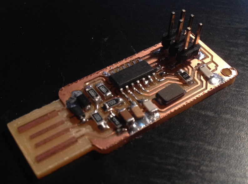
After finishing, it seems to be properly done. I checked some connections with a multimeter and they were ok, so the next step was to validate it in the programming process.
|
|
Programming the FabISP
The first thing before programming the FabISP with the programmer code it is to put the jumpers closed. During the soldering phase I did not include the jumpers, so my first idea was to was to attach some pieces of wire to the jumpers position.
Anyway, this quite difficult for me due to the small place of it, so what I did, although I know it is not the best option, is to put a lot of tin so it will close the jumper.
This week I finally had also time to create a partition on my computer and install Ubuntu on it. This was something I had in mind since the first week I was not able to run kokopelli.
The steps to programm the FabISP in Ubuntu are:
- Install Avrdude for programming and GCC to compile the C code.
- Download and unzip the firmware.
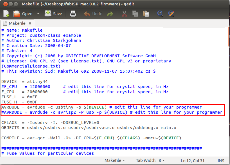
- Edit the makefile, and select if you are using another FabISP or AVRISP for programming. In the image below you see the settings to programm it from another FabISP available at FabLab León.
|
|
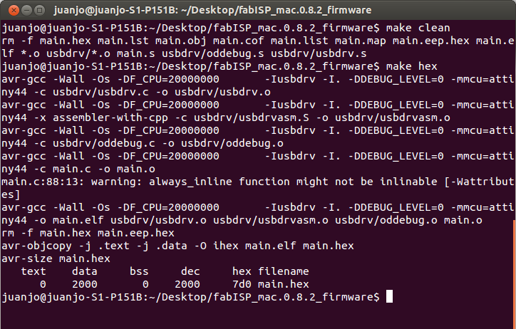
- Type make clean and later make hex in the terminal. You must see something similar to the image:
|
|
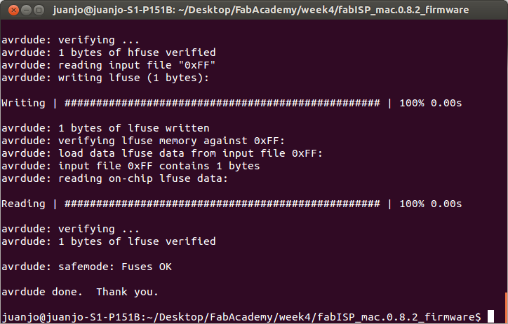
- Type sudo make fuse. At this moment, I had an error:
|
|
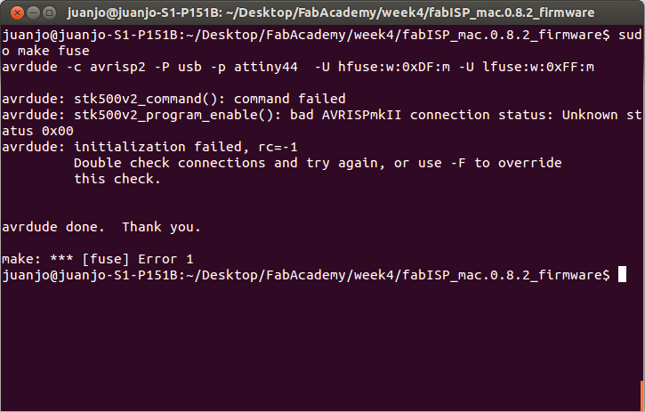
This error make me lost some time looking the reason. The first thing I did was to re-check with a multimeter all the connections in the board, and they seem to be ok.
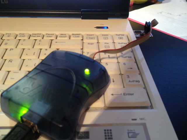
After that, I connect the FabISP to a AVRISP available at the FabLab of León. The AVRISP give you more information with a led, indicating if the device is detected or not. A green light in the AVRISP stated that the microcontroller was detected, verifying what the multimeter stated... so I felt quite fuzzy.
|
|
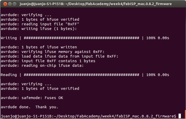
Finally, when I was very close to gave it up, I remembered something said during the lesson: the programming of the FabISP was problematic with some USB ports. My computer is quite old, so it does not include USB 3.0, which are not compatible, but anyway I decided to use a different USB port in my computer... and it worked!!! I finally was able to continue programming my FabISP.
|
|
- Type sudo make program.
|
|
Once completed the steps before, it was only remaining to clear the jumpers and my FabISP was programmed and ready to be used in the future to program more electronics boards.
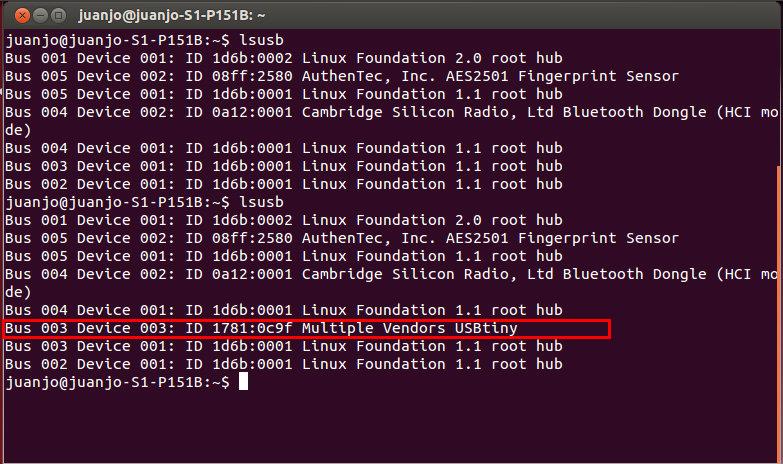
You can see in the snapshot below the FabISP recognized from the computer. The first time I run lsusb command the FabISP was disconnected and the second one connected.
|
|