Assignment for this week: build a wired &/or wireless network with at least two nodes
I used this week assignment to build and test some networking issues I’ll need for my final project.
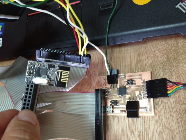
In my final project the different parts will need to connect with the main control part for transmitting and receiving messages. I am going to use RF communication and have a transceiver on each of these parts.
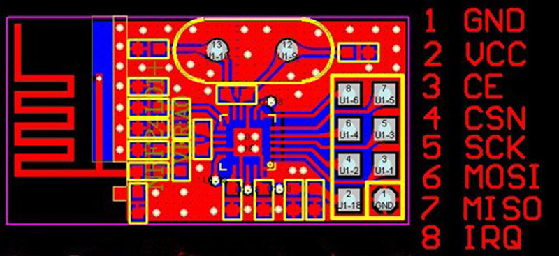
After some research I decided to use a 2.4 GHz Radio module that is based on the Nordic Semiconductor nRF24L01+ chip. (Details)
The nRF24L01
is a low-cost 2.4GHz ISM transceiver module.
It supports a number of channelfrequencies
in the 2.4GHz band and a range of data rates.
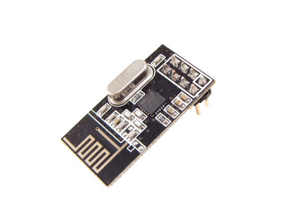
I chose this module because it is very simpl, good enough for the project needs, cheep ($1-$6) and there is a lot of documentation and samples on the web (and I got a recommendation).
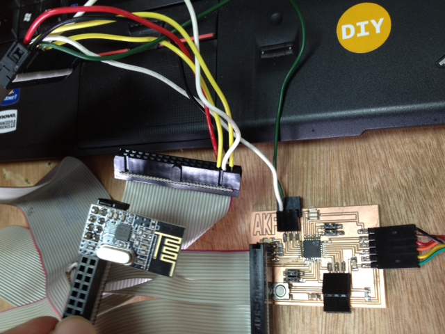
I used two RF modules for this assignment and connected each one of them to an arduino board.
Connecting with Arduino Uno:
I’ve downloaded the Nrf2401 Library from github and unzipped the archive in to my ‘libraries’ folder under the sketch folder (mine is in C:\Program Files\arduino-1.0.4\libraries)
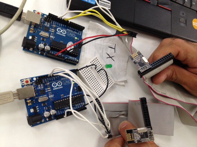
I found a sample code that work as this: as a button is clicked the transmitter send a simple message to the receiver which upon getting the message lights up a LED. I’ve changed the transmitter code a bit so it will send the message every 5 seconds without the button.
I programmed one arduino as the receiver and the other one as the transmitter.
Here is the code for the transmitter:
#include <SPI.h>
#include "nRF24L01.h"
#include "RF24.h"
int msg[1];
RF24 radio(9,10);
const uint64_t pipe = 0xE8E8F0F0E1LL;
bool status = false;

void setup(void){
 Serial.begin(9600);
 radio.begin();
 radio.openWritingPipe(pipe);}

void loop(void){
 msg[0] = 111;
 status = radio.write(msg, 1);
 if (status){
 Serial.println("sent");
 }
 else {
 Serial.println("failed");
 }
 delay(5000);
}
And the Receiver:
#include <SPI.h>
#include "nRF24L01.h"
#include "RF24.h"
int msg[1];
RF24 radio(9,10);
const uint64_t pipe = 0xE8E8F0F0E1LL;
int LED1 = 5;

void setup(void){
 Serial.begin(9600);
 radio.begin();
 radio.openReadingPipe(1,pipe);
 radio.startListening();
 pinMode(LED1, OUTPUT);}

void loop(void){
 if (radio.available()){
 bool done = false;
 while (!done){
 done = radio.read(msg, 1);
 Serial.println(msg[0]);
 if (msg[0] == 111){
 digitalWrite(LED1, HIGH);
 delay(100);
 }
 else {digitalWrite(LED1, LOW);}
 delay(100);
 }
 }
 else{Serial.println("No radio available");
 digitalWrite(LED1, LOW);
 delay(1000);
 }
}
It worked quite nicely …
Next I tried to use the same configuration using the Fabduino (Anna’s version).
It did not work for some reason (that I’m gonna find out …)
And that’s it …
an Update:
I’ve managed to work it out with the Fabduino. The problem was that the input for the RF Module needs to be 3.3v and the Fabduino VC output is 5v ….
References:
A very good place to start - nRF24L01 2.4GHz Radio/Wireless Transceivers How-To https://github.com/maniacbug/RF24 http://maniacbug.github.io/RF24Network/index.html http://playground.arduino.cc/InterfacingWithHardware/Nrf2401