WEEK 12
Fab-Weeks
Are you looking for my assignments?
Links and notes
more information:
Week 18: Proyect Development
1.- Introduction:
In a Fablab there are numerous components that are used to make each user's projects. I have dedicated my final project idea to the creation of an automatic component dispenser, which is capable of dispensing components one by one.
In a first time, there was a need for a system to dispense electronic components one by one and count the components left inside to know when they will run out or need to be recharged.
The device can be adapted according to the needs of the components that the user wants to dispense.
The GiveMe Tronics is an automatic component dispenser (originally intended for electronic components). Its manufacture can be done easily, only with a 3D printer, a small laser cutter and the necessary electronic components.
It is an Open Source project, so everything can be downloaded freely. The only condition that I propose is to share the modifications or adaptations that are made to the design so that any user can benefit in the same way.
WEEK 01
The first week I started working with the first sketches to design my final project.
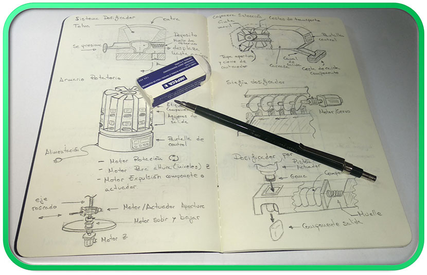
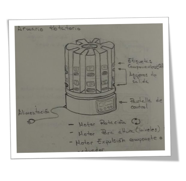
I drew several ideas about the shape it could have, different motion systems to automate the project, possible elements you might need, etc.
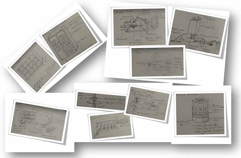
From among the shape designs, I select one as your final idea. Regarding the automatic system to dispense components, I would continue working on it.
WEEK 02
In the second week I vectorized the selected sketch of my first idea. On this sketch, I made improvements with the 3D design and tested possible parts for the automatic system. Also, I set a final idea for the automatic component dispensing system.
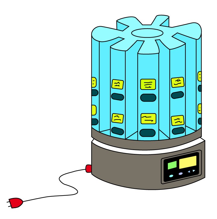
I tried to make a more approximate representation of the idea that I am working with.
As this week there was also simulation and animation, I made a video to show how the automatic device works.
WEEK 03
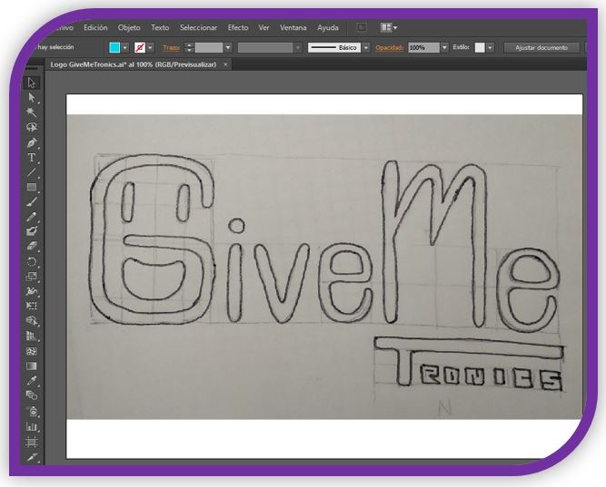
This week I have worked on the logo for my final project. It will be the mark that represents my device. With it I have made a sticker, which in the future I will place on my device.

WEEK 05
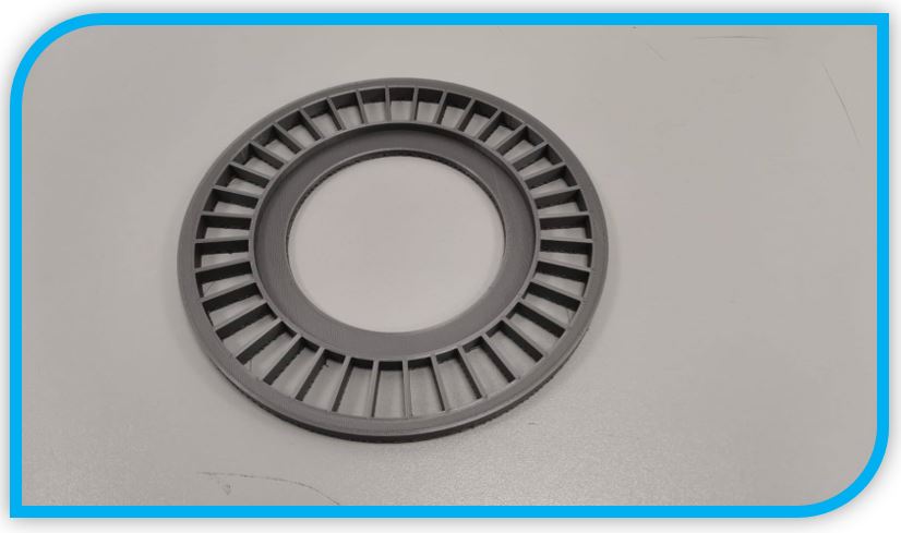
This week I have worked with the modeling of a 36-slot disk, for 36 components. It is the first disc prototype to test.
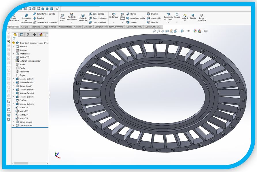
It has a system of anti-return tabs, in the lower part, which are printed without support, which allows to obtain this mobile part
WEEK 10
In week 10 I designed the HEC-TRAINER-ESP32, a board with the ESP32 microcontroller, which I have selected for the development of my final project.
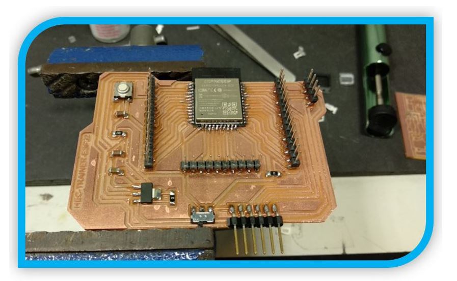
The advantage of this board is that it is created to have all the pins of the microcontroller free, in this way I can connect any input or output element to test and test which pins will be useful to connect the inputs and outputs of my dispenser. GiveMe Tornics.
In addition, I can also use this board for the development of the following weeks including the communications one, because it has the communication pins ready.
On the other hand, the ESP32 has a built-in WiFi and Bluetooth module.
This week I did not have time to do tests with an end stepper, since I used other more complex sensors as inputs.
WEEK 12
Referring to the final GiveMe Tronics project, this week I have worked on the choice of drivers for stepper motors and on the control of these motors.
In GiveMe Tronics, I will need two stepper motors, one to raise and lower the car and the other motor, it is in the car and is in charge of turning the disk and dispensing the component.
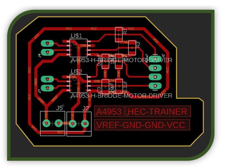
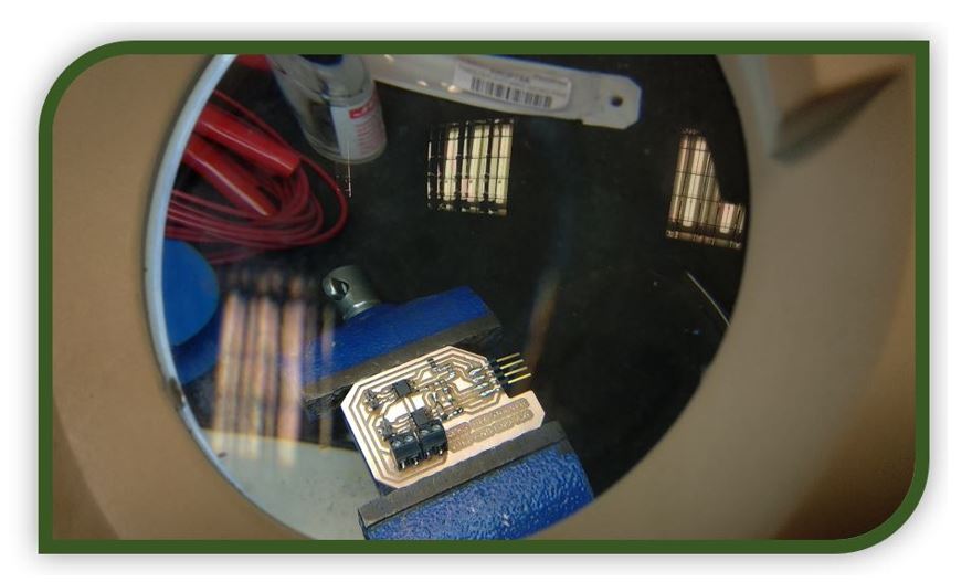
I ended up working with the A4953 driver, designing an electronic board to control the stepper motor.
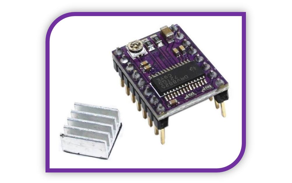
Although finally, due to the problem that a driver broke, I decided to use the DRV8825 Driver modules on the GiveMe Tronics integral board.
WEEK 13
In this week of communications and networks, I began to test the ESP32 WiFi module to test how it works.
In addition, I had time to try a small interface with the ESP32 web server to turn on and off a pair of LEDs remotely, connecting through a web browser using the IP address.
WEEK 14:
Working on the final project, I have been doing the tests with the Bluetooth module and an application created with MIT Inventor, which is responsible for controlling the on and off of LEDs remotely.
Mo works poorly and using the Bluetooth module is not a bad option. But finally for GiveMe Tronics I will use the WiFi module to make a web server with the ESP32 to control the dispenser.
I think that WiFi is "more universal" when it comes to connecting via web browser, unlike Bluetooth that can cause problems depending on the different versions of each device.
WEEK 16:
As I mentioned, this week I have worked with the final choice of materials for the GiveMe Tronics project and its final preparations and objectives.
I have also started working on the bill of materials, with which I will also know the final cost of the project.
WEEK17
This week I have chosen the type of license that my final project will have, which will be an open one so that anyone can use GiveMe Tronics, update it and share their updates and modifications with other people.
I have also worked on the slide and the video of the final presentation.
2.- Development of the structure:
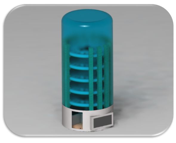
From the first sketches with the idea of the project and the first render, which had a more cylindrical shape, the project has evolved and changed little by little.
The first render, although it changes the visual aspect, I think it is quite explanatory to see that there is a system that goes up and down, another that pushes the disk and makes it rotate and in this way the component is free and falls.
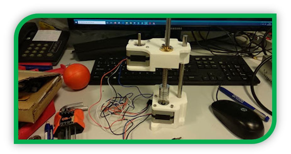
The first thing I started working with was the parts to fix the stepper motors and the rods.
The first version has two pieces, which I made in black PLA. The bottom part is used to fix the motor to the base of the dispenser. This stepper motor drives the wand to raise and lower the carriage.
The other black part is the car, the car is responsible for fixing the other stepper motor and making it go up and down so that it can activate the different levels of storage of components.
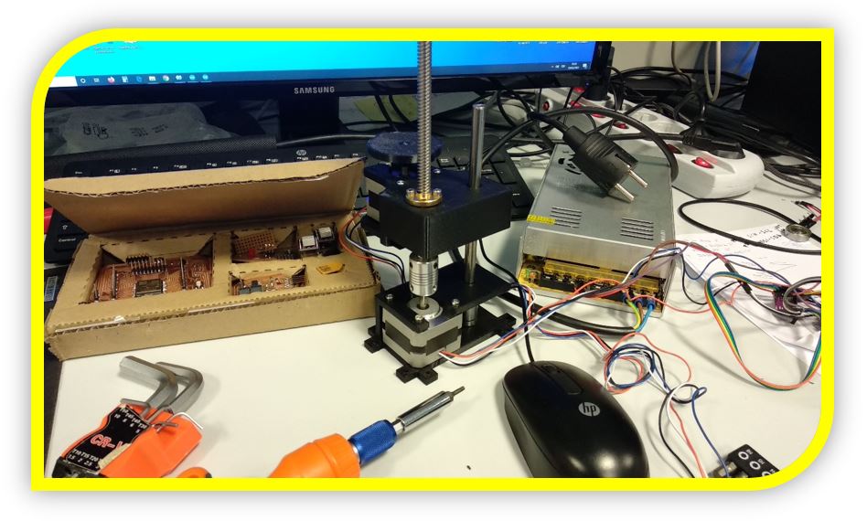
The two pieces have two holes so that two rods can pass, one smooth and the other threaded (the one that transmits the movement, like the advancement of a screw).
In this assembly I also tried the first design of the gear that turns the discs. It is a two tooth gear. Its function is that each time the motor rotates a half turn (100 steps), the teeth rotate 180 degrees and move the dispensing discs one space (each space is 10 degrees of rotation of the level disc) dropping a component.
The first test with this assembly was to raise and lower the cart.
I did not like it very much, the idea was to use only two rods to simplify the system, but the system is very unstable.
The problem with having the system unstable is that when raising or lowering the level I can collide with the teeth of the other intermediate discs.
As I was testing, I took the opportunity to test the turning system of the dispensing discs, with the two-tooth gear.
The system worked for me, but I didn't like it very much. The reason, the contact surface between the two-tooth gear and the disc teeth, was very small, on the drawing and the assembly with Solid it looked very good, but in reality, I think it can give problems if there is a small Lag or error in the assembly, when selecting and activating the different levels.
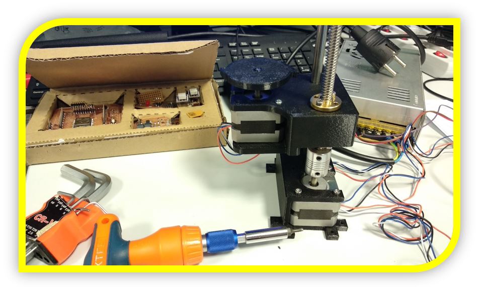
Knowing these test results, redesign the structure for the drive system with the dispenser stepper motors.
The pieces were also printed with PLA, in this case white.
The result of the redesign of the new assembly is a much more solid and precise structure.
I liked its operation, practically without vibrations.
Now that the raising and lowering system has a final result, redesign the gear. The new gear has 20 teeth.
Why 20 teeth ?:
Each dispensing disk has 36 spaces for components (but it must be taken into account that one of them is always empty, because it is the one that coincides with the dispensing chute. So each disk stores 35 effective components + 1 free space). Each space of the dispensing disc is separated by 10 degrees, each time you want to dispense a component you have to rotate 10 degrees.
The 20 tooth gear, on the other hand, has each tooth separated by 18 degrees. These 18 degrees are equivalent to taking 10 steps with the motor (since 1 step of the stepper motor is 1.8 degrees). Each turn of the gear at 18 degrees or 10 steps, the dispensing disk rotates the 10 degrees it takes to dispense a component.
With this new gear, the contact surface between the teeth works very well. The result can be seen in the video. (The gear is not properly engaged, so it looks tilted, but then I placed it correctly and the end result does not have a tilted movement).
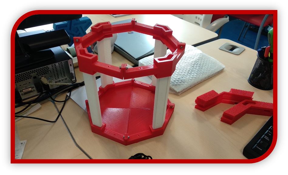
Since the stepper motor assembly works, I am going to assemble the base of the GiveMe Tronics dispenser frame.
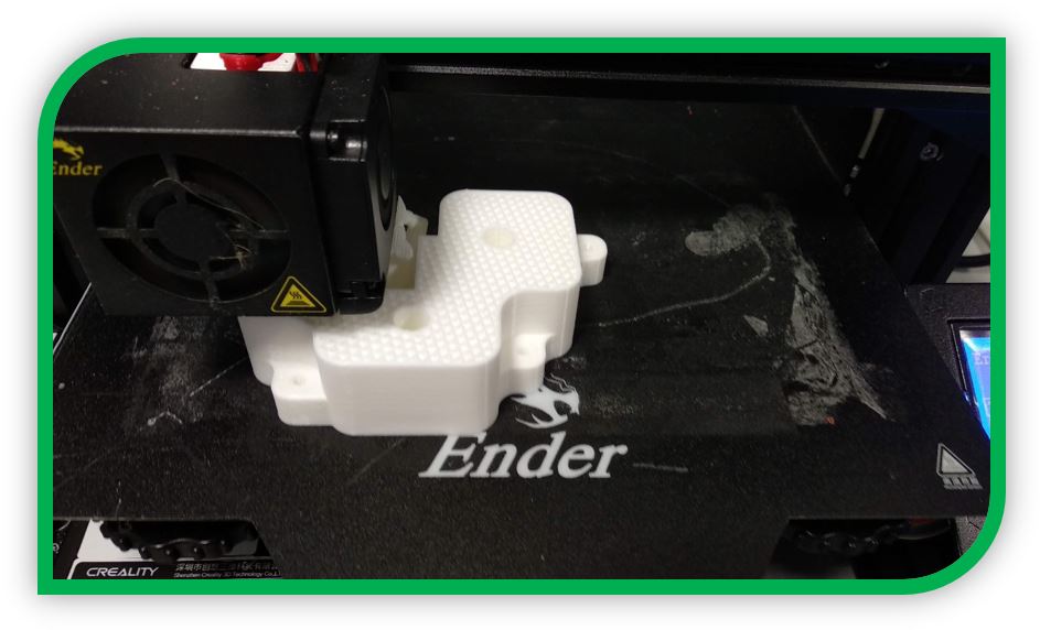
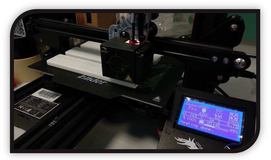
I have also made these pieces of the base of the structure with white and red PLA. I have adapted the size of the pieces so that they can be printed with a desktop size printer, with a bed of (200x200) mm which is usually the most standard. I have mainly used an Ender 3pro:
Also, to save time, I have used another dual head printer and size for medium parts. It is a Sigmax R19 model:
Base printed with Sigmax 3D printer. In this base, I have placed 4 nuts embedded in the piece, to screw the previous assembly of the elevator system.
I assemble the structure:
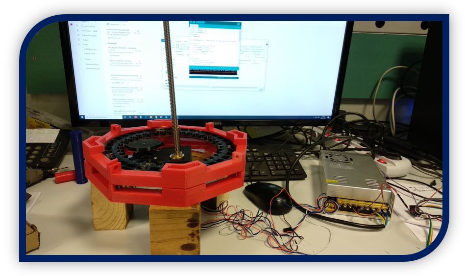
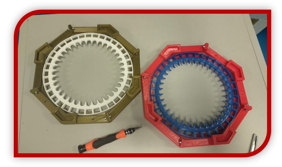
And at the same time, I go with the manufacture of the structure of the levels with their discs.

As you can see in the photo, the walls of the levels are made of PLA in bronze and red, colors like those of the Ironman armor, which will give the name of my first version of GiveMe Tronics.
The tooth disc is also made with white and blue PLA, depending on the level.
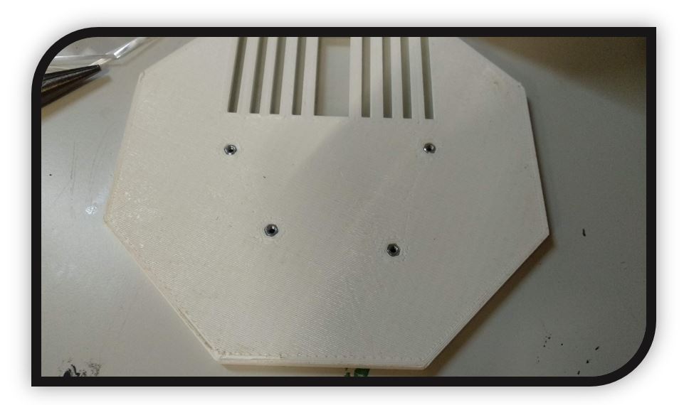
All levels have a base for the discs made of acrylic, the purpose of this base is to act as a "rail" for the disc and thus keep it in the central position. In addition, I have chosen acrylic because it is a smooth material that favors turning. For the manufacture of this acrylic part I have used laser cutting.
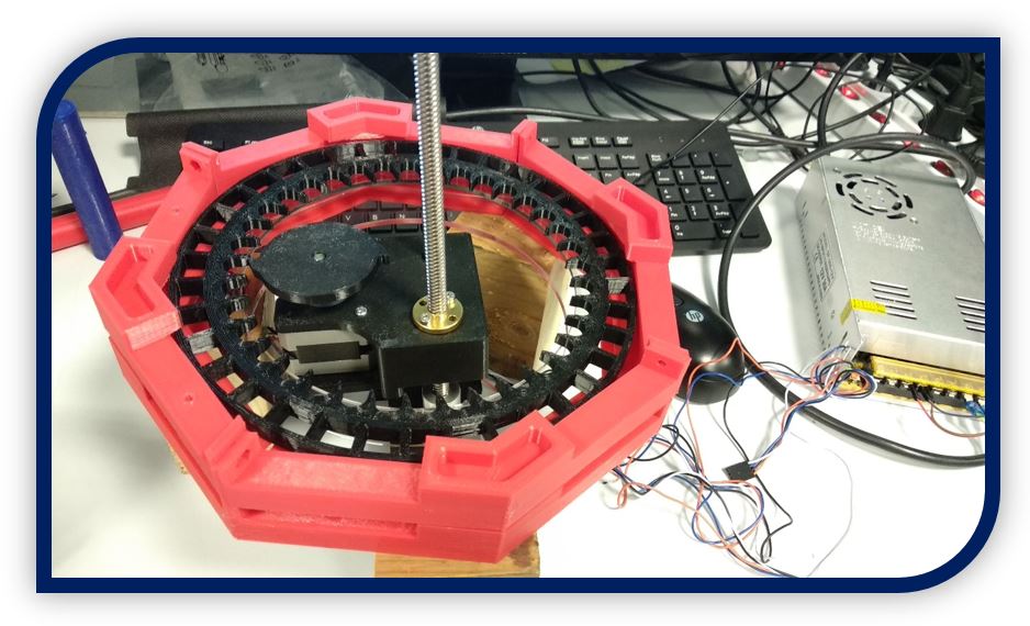
The assembly of the discs, with the colors for the IRONMAN version, is as follows:
In 4 of the octagonal corners of the levels, there are female slots at the top and male slots at the bottom, these slots are to attach the discs without using screws or anything else. In this way they can be removed or placed to recharge their holes with more components or to remove or add levels if you want a larger or smaller dispenser.
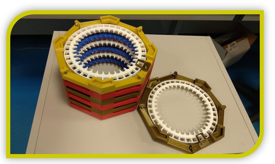
When I finished a couple of levels, I started testing and checking for the final settings.
Tried it to rotate easily by hand:
And from this point, I started with the different tests with the programming of the board. For example, the first settings for turning with the end plate and testing the turning motion of the motor.
Testing how the disk rotates with the gear by indicating a number of steps with the Arduino serial monitor.
When I proved that it was already spinning well, I began to work on programming with the web server interface and the first tests to dispense components of the same level.
Then with the tests dispensing components of one level and switching to dispense components of another level.
With this I have a first final performance of the first version, IRONMAN, of GiveMe TRONICS.
3.- Development of Electronics:
The GiveMe Tronics electronic board has been designed in an integral way, in a single electronic board, everything necessary for the dispenser to work is included.
I started working with a board that I designed with a single 3.3V regulator.
This board has the disadvantage that every time you want to program, with the FTDI cable you have to disconnect the 12V source with which only the dispenser is powered. If not, the 12V will be in direct contact with the 5V from the FTDI cable and something will burn on the device.
This is so because the 5V from the FTDI goes to the regulator to become 3.3V and the 12V from the source also goes to the same regulator to become 3.3V, so the 5V and 12V lines are connected to the input of the regulator. That is why the cable must be disconnected.
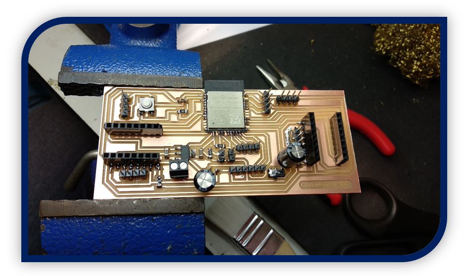
Suddenly, one day doing tests, something happened to the plate. My VCC line was shorted to GND at some point that I couldn't detect.
Taking advantage of this failure and that I was tired of connecting and disconnecting the 5V and 12V sources so that they were not active at the same time, I redesigned the board so that everything could be connected without problems.
The new and definitive design for the GiveMe Tronics electronic board is as follows:
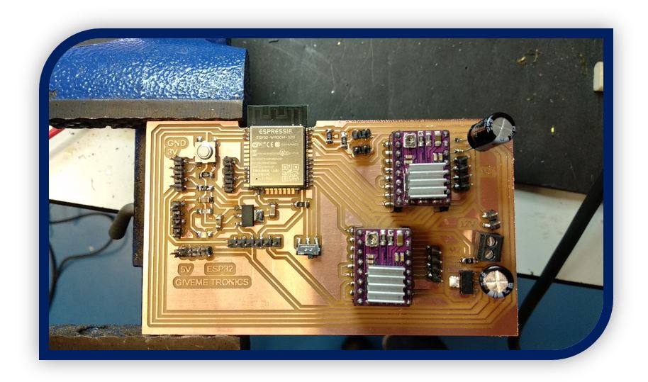
This board uses the same components and as an addition it has a 5V regulator. So with this upgrade, the 12V from the power supply powers the motors and goes to the input of the regulator to become 5V. These 5V can be connected to the entire line that is in contact with the FTDI programming cable and end in the other regulator, where they become 3.3V that are the ones that feed the ESP32 microcontroller.
With this solution I can have everything connected safely, without anything burning.
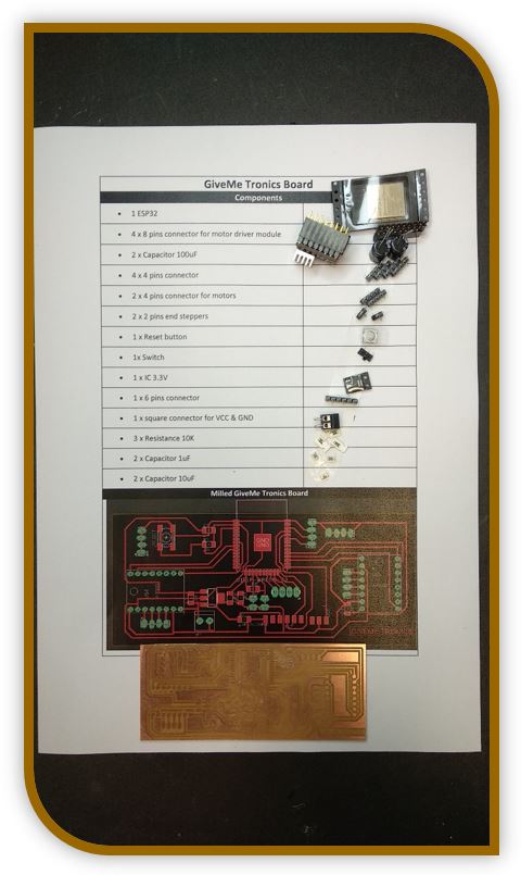
SPEAKING A LITTLE MORE ABOUT THE GIVEME TRONICS BOARD:
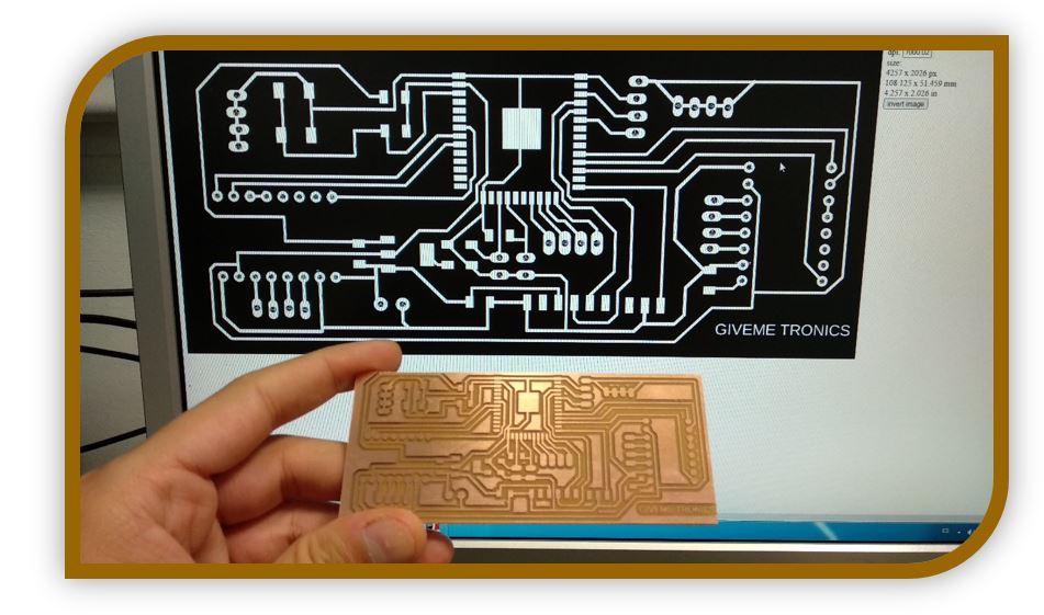
The design of the electronic boards of which I have spoken, I have made them with the Eagle software:
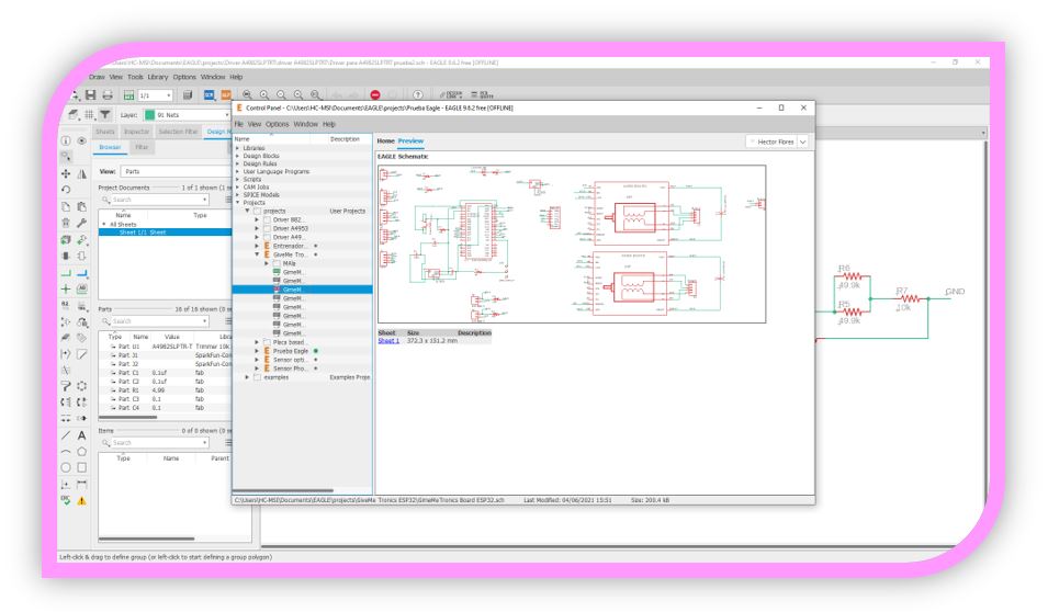
The definitive schematic model is represented in the image:
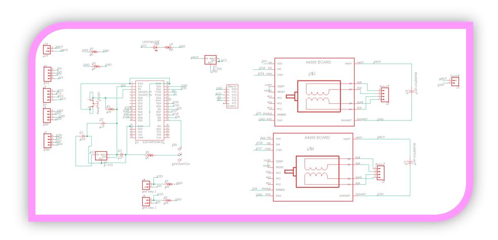
And your resulting model for milling is:
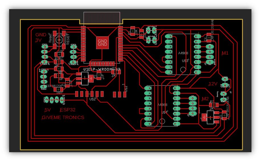
As you can see, it is a board that allows you to make some modifications, by leaving some pins free. The characteristics of the plate are as follows:
■ The main element of the electronic board is the ESP32 WROOM microcontroller with built-in WiFi and Bluetooth module.
■ DRV8825 modules are built-in, just insert them into their sockets.
■ On the right side, the 12V source is connected to power the stepper motors.
■ With the 12V power supply, two pins (12V) have been left free in case you want to include an additional element that works at that voltage.
■ From the 5V line, 5 pins have been left free to connect devices at this voltage.
■ In the same way, with the 3.3V line, another 5 pins have been left free.
■ There are also 5 free GNDs for additional connections.
■ The microcontroller has 4 pins released to connect other types of inputs or outputs.
■ Another connection has been installed for another limit switch if necessary.
■ Additionally, the FTDI pins, as long as they are not used for programming or viewing through the serial port, can be used as inputs or outputs for the microcontroller.
The board has been manufactured with the StepCraft milling machine, using a 0.4mm bit for the electronic tracks and a 0.8mm bit to cut the electronic board.
4.- The control web environment:
GiveMe Tronics is controlled by a web server hosted on the ESP32 microcontroller. Communication with the server is done through a WiFi connection within the same network.
The web server is accessed through any browser, only by entering the IP address assigned to the microcontroller within the WiFi network (for example 192.XXX.XXX.XXX).
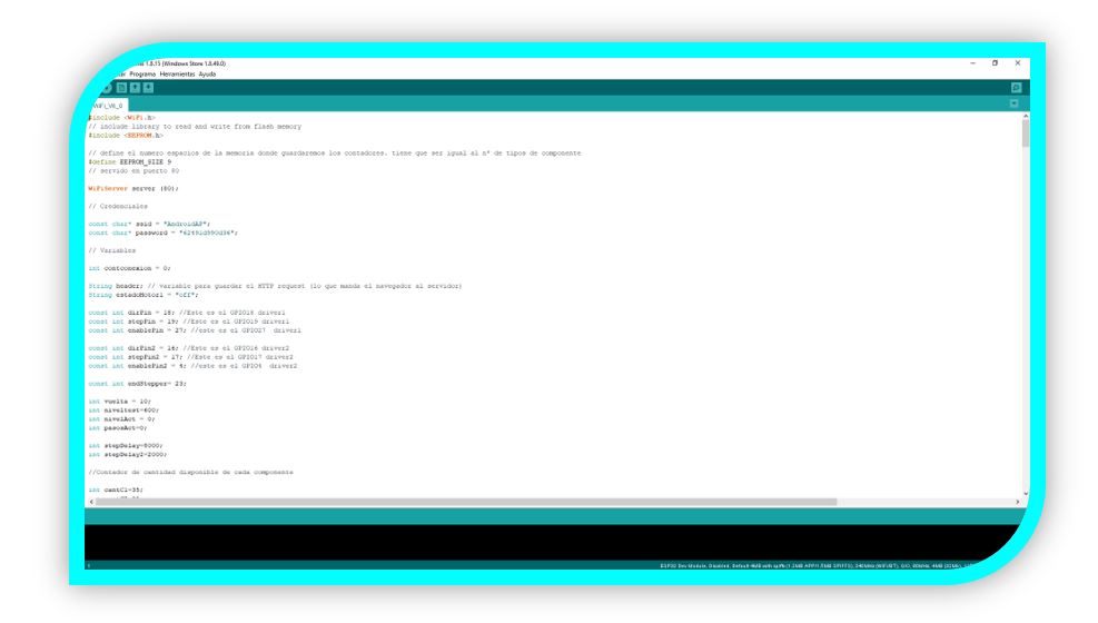
When the connection is made, the web page will appear in the browser with the buttons to control the dispenser remotely. The HTML code for this control web page is embedded in the file with the dispenser programming code (in this case I have embedded it at the end of the file with the code inside a string variable).

Through programming, the microcontroller is responsible for reading if we click on any of the buttons on the web page, when we click on one, the microcontroller reads the marker of that button and knows what level and component to dispense. Then it activates the motor to raise or lower the car, up to the height of the indicated level. When it reaches the level, the stepper motor for raising and lowering the carriage stops. The microcontroller then activates the gear rotation motor to rotate the dispensing disk and drop the component at that level down the dispensing conduit. This is the summary of the operation of the code to dispense components automatically and remotely.
The visual aspect of the control web, in this first version of GiveMe Tronics is a bit simple.
It has the first 4 buttons that are to activate the dispenser manually, either to test its operation, or if it were necessary to dispense a component less automatically.
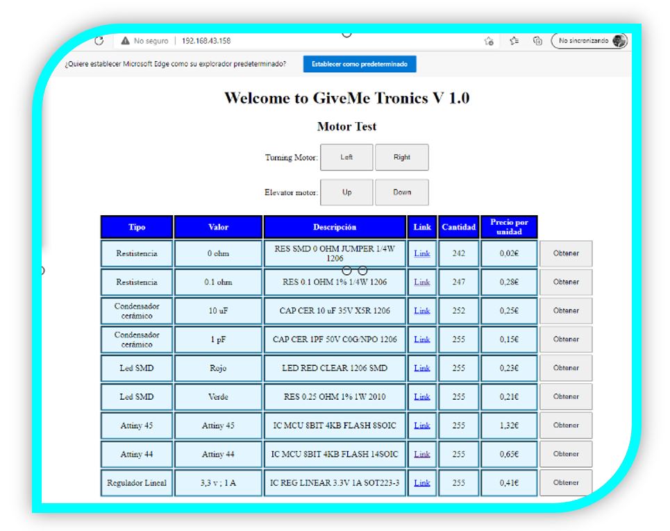
Below these buttons, you have the fundamental basis for controlling the dispenser, and what makes it functional as is. It is a table that shows the levels in different rows, and in each row, by columns, the information is displayed: what level it is, what component it contains, what is the component code, information and a link about the component, its price, the number of components remaining inside the disk and next to each row, the button to activate the dispensing of the component at each level.
Verifying the correct operation of the control web, I recorded this video:
THE FINAL RESULT
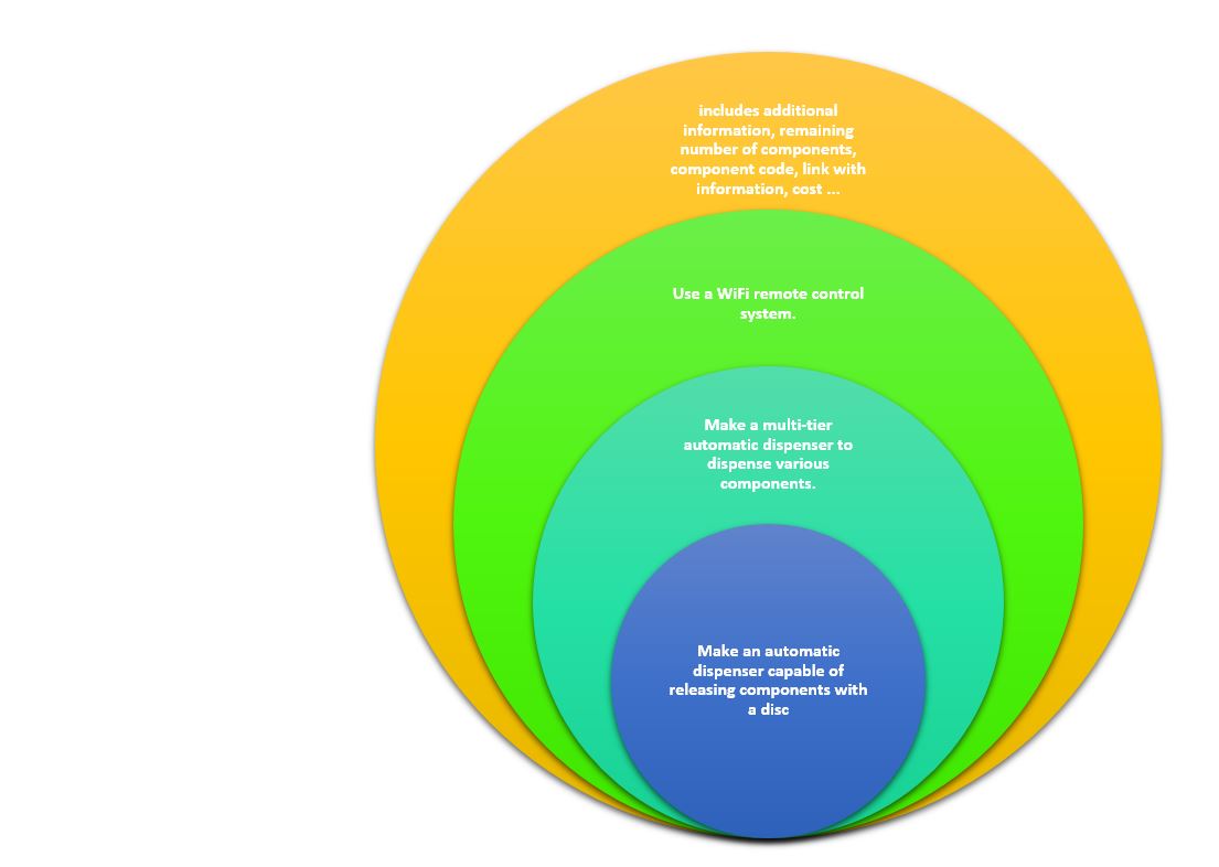
5.- Spiral development:
1. Make an automatic dispenser capable of releasing components with a disc.
2. Make a multi-tier automatic dispenser to dispense various components.
3. Use a WiFi remote control system.
4. Create a control environment that, in addition to dispensing the components, includes additional information, remaining number of components, component code, link with information, cost ...
6.- Material's list:
| Part | Material & Comments | Price | Source |
|---|---|---|---|
| Disc frame (octagonal) (4 pieces, 1 tier) | PLA (17h 39min) 163gr [Ender 3pro printer] | 4,08€ (per nivel) | Filament2print |
| First level structure (octagonal) | PLA (19h 32min) 175gr [Ender 3pro printer] | 4,38€ | Filament2print |
| Frame base (octagonal) 1unit (4 required) | PLA (4h 23min) 45gr [Ender 3pro printer] | 1,13€ | Filament2print |
| Pillars the 4 units | PLA (11h 22min) 137gr [Ender 3pro printer] | 3,43€ | Filament2print |
| Fixing base 1 | PLA (9h 3min) 106gr [Ender 3pro printer] | 2,65€ | Filament2print |
| Disk1 | PLA (6h) 47gr [Ender 3pro printer] | 1,18€ | Filament2print |
| Base for 1st Nema17 and trolley for 2nd Nema17 | PLA (13h 47min) 146gr [Ender 3pro printer] | 3,65€ | Filament2print |
| Gear | PLA (1h 38min) 17gr [Ender 3pro printer] | 0,48€ | Filament2print |
| Top cover | PLA (6h) 58gr [Ender 3pro printer] | 1,45€ | Filament2print |
| End stepper support | PLA (39min) 6gr [Ender 3pro printer] | 0,15€ | Filament2print |
| 14 pieces for protection wall bracket | PLA (5h 27min) 40gr [Ender 3pro printer] | 1€ | Filament2print |
| Wall pack x2 (necesitan 4pack) | PLA (1h 20min) 20gr [Ender 3pro printer] | 0,50€ | Filament2print |
| Dispenser output | PLA (6h 38min) 57gr [Ender 3pro printer] | 1,43€ | Filament2print |
| 9 ducts for outlet | PLA (2h 49min) 24gr [Ender 3pro printer] | 0,60€ | Filament2print |
| Electronic Board Support | PLA (50min) 6gr [Ender 3pro printer] | 0,15€ | Filament2print |
| Acrylic disc bases (1 per level) | Acrylic (2min) 50cm x 20cm a table of 50cm x 100cm | 8,47€ | PerezCamps |
| Milling | Copper Board (100 x 127)mm (3h milling) | 1,60€ | Digikey> |
| Nuts and bolts | M3 (3mm) pack diferent lenght | 12€ aprox | Amazon |
| 2 smooth rods | 2 x (8mm x 200mm) | 10€ (both) | Amazon |
| 1 threaded rod | 1 x (8mm x330mm) | 9,25€ | Amazon |
| 2 Nema17 engines | NEMA17 1.3A 40mm | 34€ (both) | Amazon |
| 1 Flexible fixation | (6 x 8 x 25) mm, Diameter: 19 mm | 1,80€ | Amazon |
| 3 bearings model1 | Diameter 8mm | 2,07€ (the three) | Amazon> |
| 2 bearings model2 | Diameter 8mm | 1,54€ (both) | Amazon |
| 1 ESP32-WROOM-32D | WIFI MODULE 32MBITS SPI FLASH | 3,44€ | Digikey |
| 1 5V regulator | 5 v ; 1 A | 0,34€ | Digikey |
| 1 3V regulator | 3,3 v ; 1 A | 0,39€ | Digikey |
| 2 DRV 8825 driver modules | DRV8825 18pins | 5€ (both) | Amazon |
| 2 100uF capacitors | Row:30 Cell:2 | 1,50€ (both) | Amazon |
| 3 0K resistors | RES SMD 0 OHM JUMPER 1/4W 1206 | 0,06€ (the three) | Digikey |
| 3 10K resistors | RES SMD 10K OHM 1% 1/4W 1206 | 0,09€ (the three) | Digikey |
| 2 1uF capacitors | CAP CER 1UF 50V X7R 1206 | 0,38€ (both) | Digikey |
| 1 10uF capacitor | CAP CER 10UF 35V X5R 1206 | 0,14€ | Digikey> |
| 1 1K resistor | RES SMD 1K OHM 1% 1/4W 1206 | 0,03€ | Digikey |
| 1 smd LED (blue) | LED BLUE CLEAR CHIP SMD | 0,36€ | Digikey |
| 1 reset button | SWITCH TACTILE SPST-NO 0.05A 24V | 0,92€ | Digikey |
| 1 switch | SWITCH SLIDE SPDT 100MA 12V | 0,87€ | Digikey |
| 39 Male connection pin | CONN HEADER SMD 40POS 2.54MM | 3,9€ | Digikey |
| 32 Pin female connection for driver | CONN HDR 8POS 0.1 TIN PCB | 3,2€ | Digikey |
| 1 square 2-pin power connector | TERM BLK 2POS SIDE ENT 3.5MM PCB | 0,54€ | Digikey |
| TOTAL | 166,00€ |
7.-FILES
GiveMeTronics parts
Assembly video
Laser cutting files
ESP32 files (programming)