WEEK 10
- 1.-Introduction
- 2.-Teamwork
- 3.- Choice ESP32
- 4.- Sensor VL530X (Time of Flight)
- 5.- Sensor PT15 (Phototransistor)
- 6.- Programming
- 7.- Testing
- 8.- Upgrades
- 9.- Experience and conclusions of the week
- 10.- FILES
Input devices:
Teamwork
Individual Assessment
Fab-Weeks
Are you looking for my assignments?
Links and notes
more information:
Week 10: Input Devices
1.-Introduction:
In this week I am going to work with the ESP32 microcontroller, because it can be useful for my final project, since it has a wireless connection module in addition to the possibility of connecting possible sensors that I may need.
So as not to be creating a board for each sensor that may need to test or device, I am going to create a "trainer" board that has all the pins of the outputs and with which I can couple other boards or modules, to test.
Week Journal:

2.-Teamwork
If you want to know the group assessment of this week, click on the image of SediCupCt.

3.- Choice ESP32
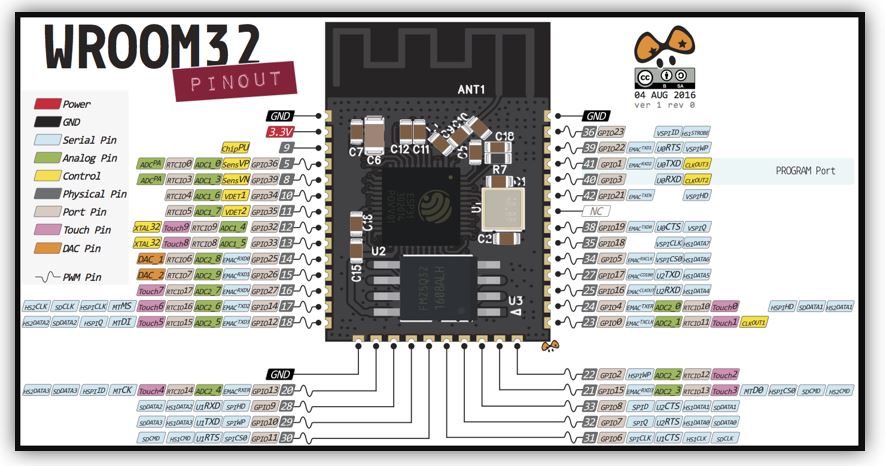
To know the connections to create the board, I first have to know what the pins of my microcontroller are. Also, I need to know what elements I have to implement so that it is possible to program it (with this microcontroller it is necessary to limit the voltage from 5V to 3.3V). In addition, I will include on the electronic board, the pins for I2C communications.
Datasheet:
ESP32 datasheet_en.pdf
My microcontroller has a Wifi connection, so the model within the ESP32 family is the WROOM32.
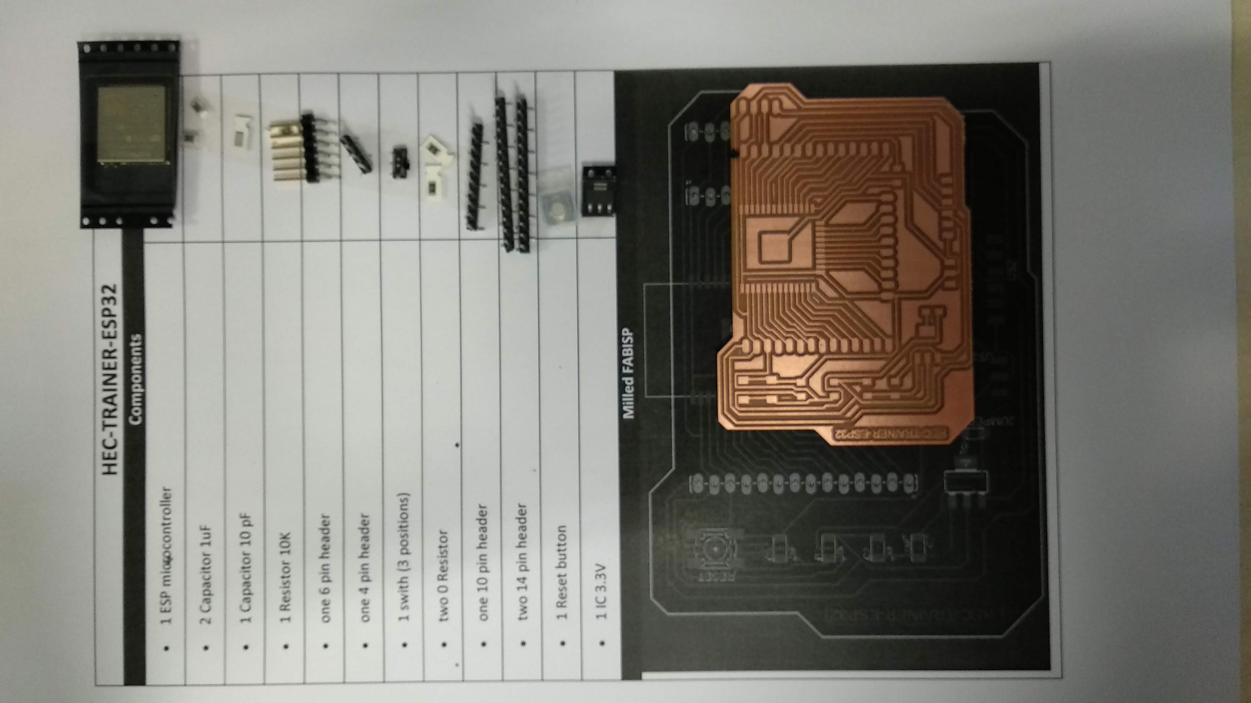
BOARD LAYOUT FOR ESP32: HEC-TRAINER-ESP32
For the design of the HEC TRAINER ESP32 board, I am going to use the Eagle software. Used in previous weeks.
As the ESP32 has not been used yet with my Eagle, the first thing is to install its library.
For example, these are two library links for the ESP32:
https://esp32.com/viewtopic.php?t=7004
https://github.com/lpodkalicki/eagle-libraries/tree/master/ics
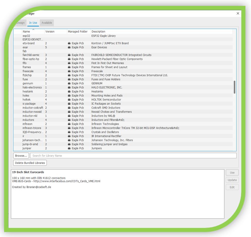
To do this, the ESP32 Library manager.
I select the encapsulation that I am going to use and edit to adapt to my milling machine and I double click on its name, in my case the ESP-WROOM-32.
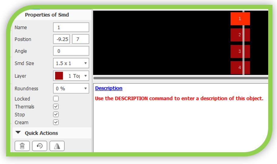
NOTE: To mill the electronic board with my 0.4mm bit, I need to modify the pins of the footprint.
Now, in the new window, press the command "Footprint".
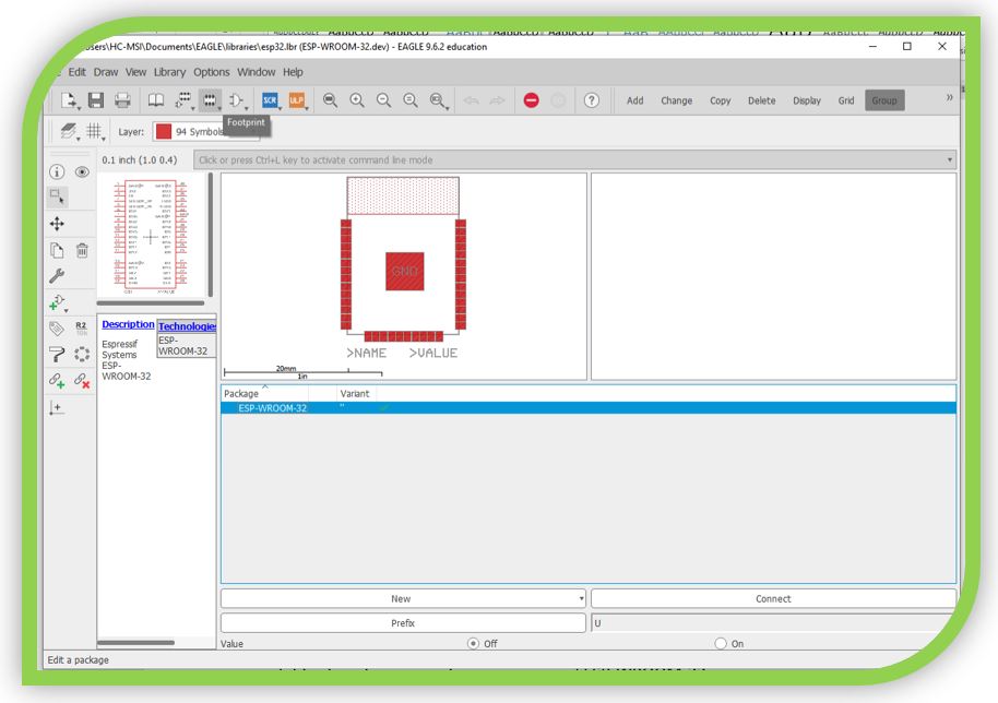
I select the package and I can edit.
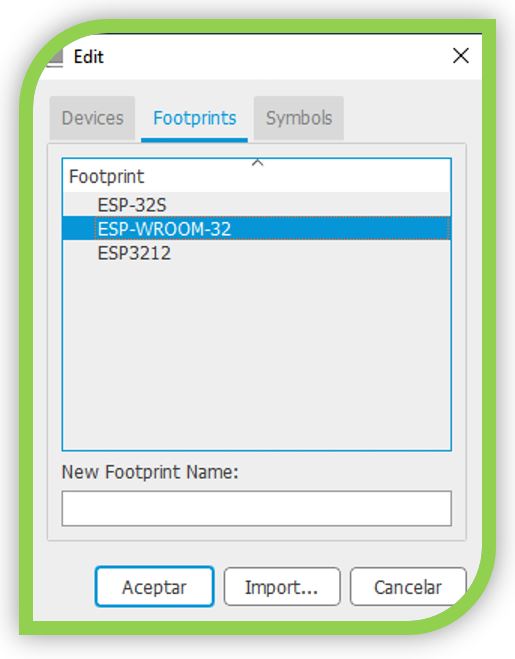
From Grid, I set the units in mm.
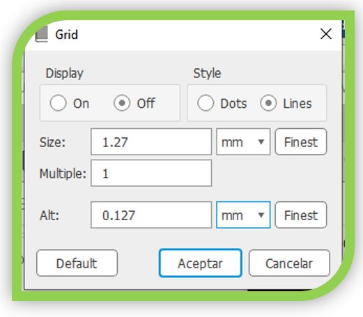
I select the pin or pins to edit and in "Smd Size" I configure the dimensions (2 x 0.8) in mm.
To draw the board, I have used the information from the Datasheet, to place the programming port correctly. In addition, I have also used the information provided by Neil.
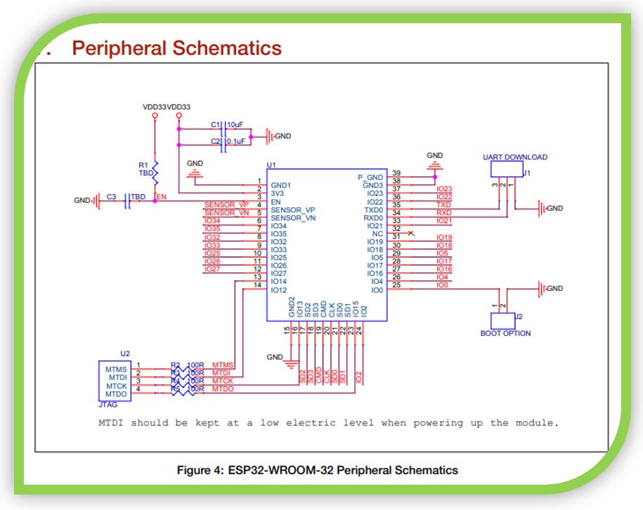
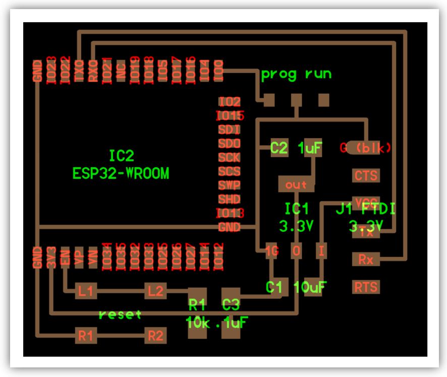
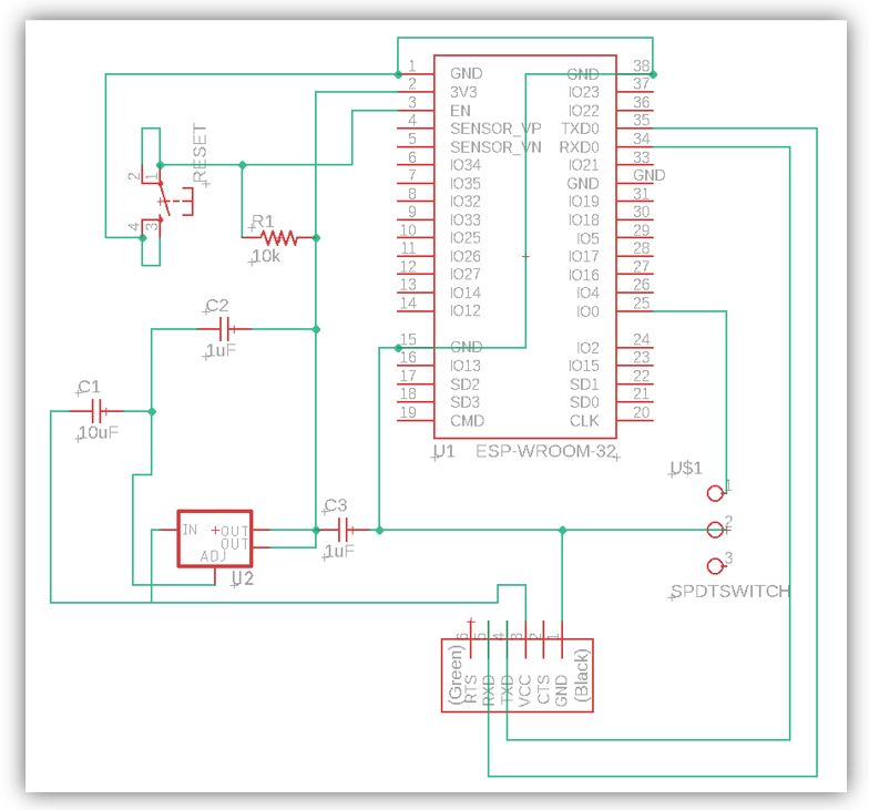
With this information, this is the first schematic I have drawn.
Schematic without connecting all free pins:
Schematic with the connection of the free pins, to connect multiple elements:
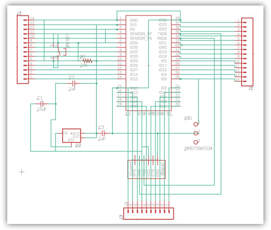
Note: I FORGOT TO PUT THE I2C (although if it is not needed, it is a valid design).
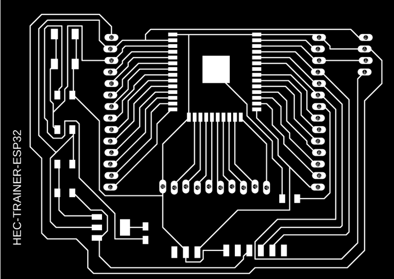
PNG milling of circuit tracks.
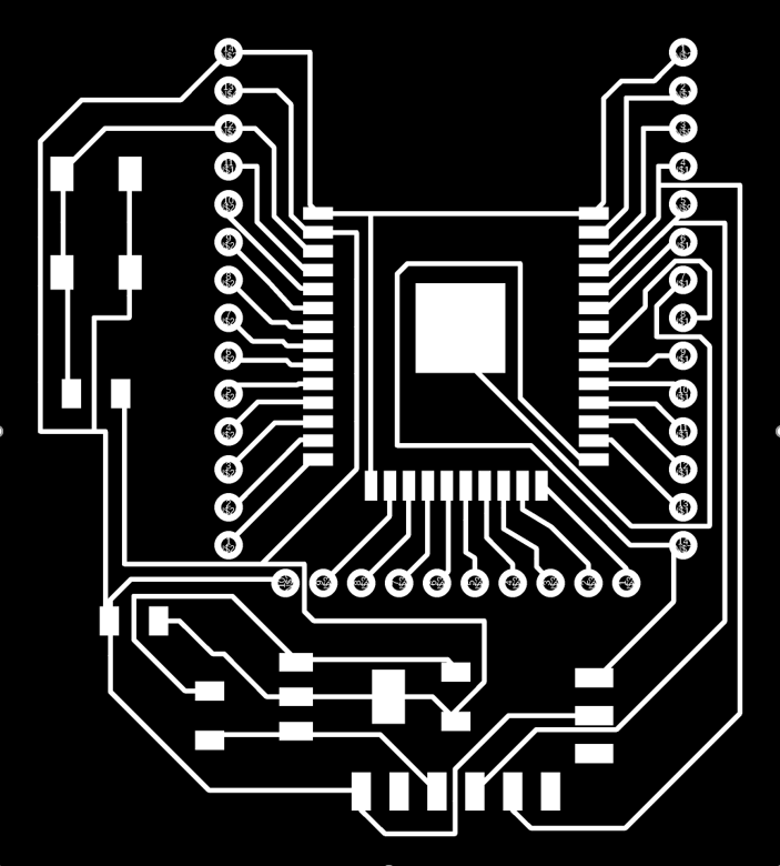
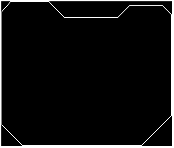
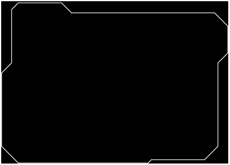
PNG circuit cutter milling.

Including the I2C communication port
With this new design, I include the I2C communication port on the board. Although when making the board quickly, I forgot to configure the general parameters, so it does not apply to my bit size.
This is the first attempt with the I2C, but I forgot to set the tracks for the 0.4mm milling bit, so I had to reconfigure. This design has a width of 6mil, about 0.15mm.
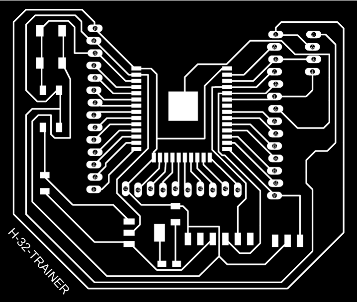
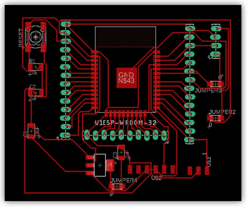
My Final Design HEC-TRAINER-ESP32:
Including design rules for the 0.4mm milling bit.
Also for this design I have lowered the ISP connectors so that they are closer to the edge of the electronic board.
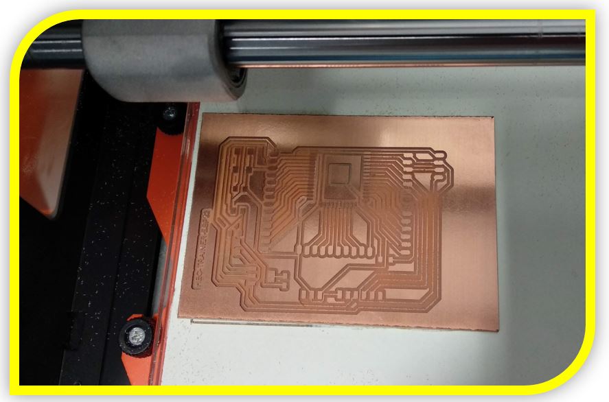
Milling the board:
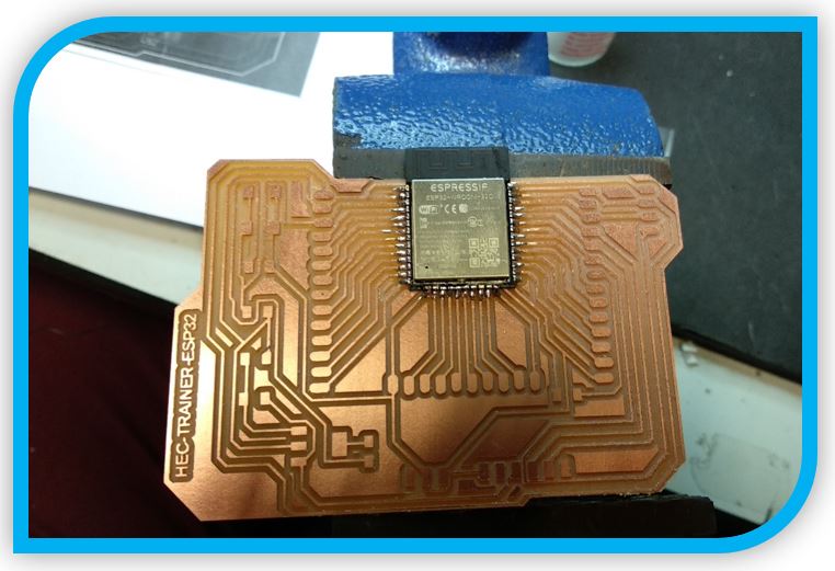
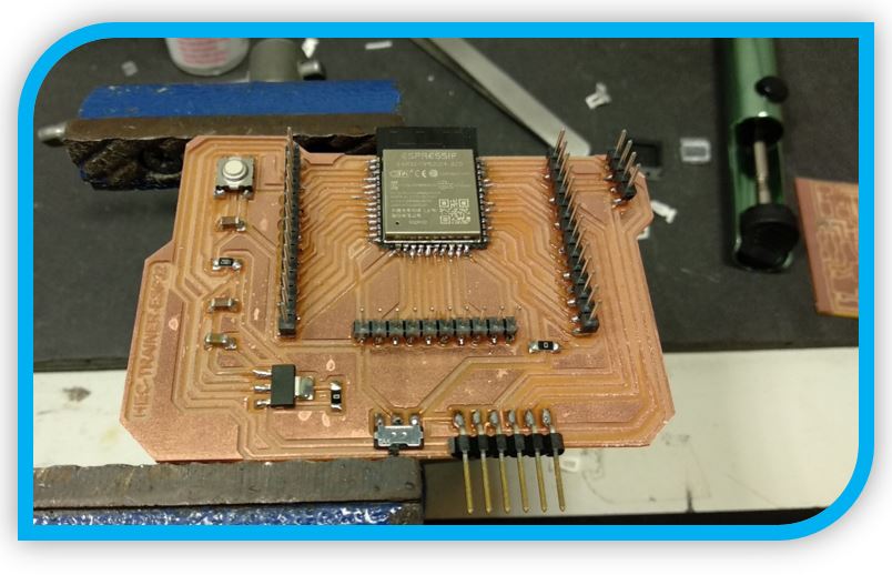
Soldering the board:
4.- Sensor VL530X (Time of Flight)
The VL53L0X is a Time-of-Flight laser infrared distance sensor, which we can use together with a microprocessor to accurately measure distances from 50mm to 2000mm.
Its operation consists of sending a laser pulse of infrared light and measuring the time required for the beam to return to the sensor.
The integrated incorporates a 940nm VCSEL (Vertical Cavity Surface-Emitting Laser) laser emitter, a SPAD (Single Photon Avalanche Diodes) detector and internal electronics (called FlightSenseTM) that perform the necessary calculations.
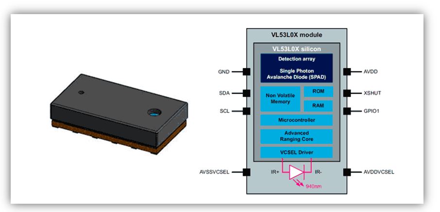
The measurement angle or FOV (Field of View) is 25º. This translates into a measurement area of 0.44m in diameter at a distance of 1m.
The measurement range depends on the environmental conditions (indoor or outdoor), the characteristics of the lens, and the operating mode. In general, we have two modes. The standard is 50 to 1200mm, and an extended mode up to 2000mm.
VL53L0X is a ranging and gesture detection sensor.
CALIBRATION:
There is an initial, once only, calibration step required that should be applied during the manufacturing process.
o VL53L0X_DataInit() function is called one time, and it performs the device initialization. To be called once and only once after device is brought out of reset.
o Ref.
o Temperature calibration.
Ref calibration is the calibration of two parameters (VHV and phase cal) which are temperature dependent. These two parameters are used to set the device sensitivity.
Ref calibration allows the adjustment of the device sensitivity when temperature varies.
Ref calibration must be performed during initial manufacturing calibration; it should be performed again when temperature varies more than 8degC compared to the initial calibration temperature.
If temperature does not vary, the ref calibration data can be loaded without re-performing the calibration procedure.
o Ref calibration procedure
User has two options:
1. Perform the calibration after VL53L0X_PerformRefSPADManagement, by calling VL53L0X_PerformRefCalibration().
2. If user wants to improve the boot time, they can load only the calibration parameters after VL53L0X_PerformRefSPADManagement by using VL53L0X_SetRefCalibration(). This assumes that user has previously performed a calibration and stored the two parameters in the Host memory.
o Offset Calibration
Range offset is performed during Final Module Test at STMicroelectronics, and the offset is stored into the device NVM.
For some cases, it can appear that the value programmed in the NVM is not correct. This can happen when the user is using a cover window. In this case, ranging can be affected by an offset, due to the cover window and so the customer should perform a new offset calibration on its manufacturing line.
A good example with code to start testing and learning about this sensor is this:
https://github.com/adafruit/Adafruit_VL53L0X
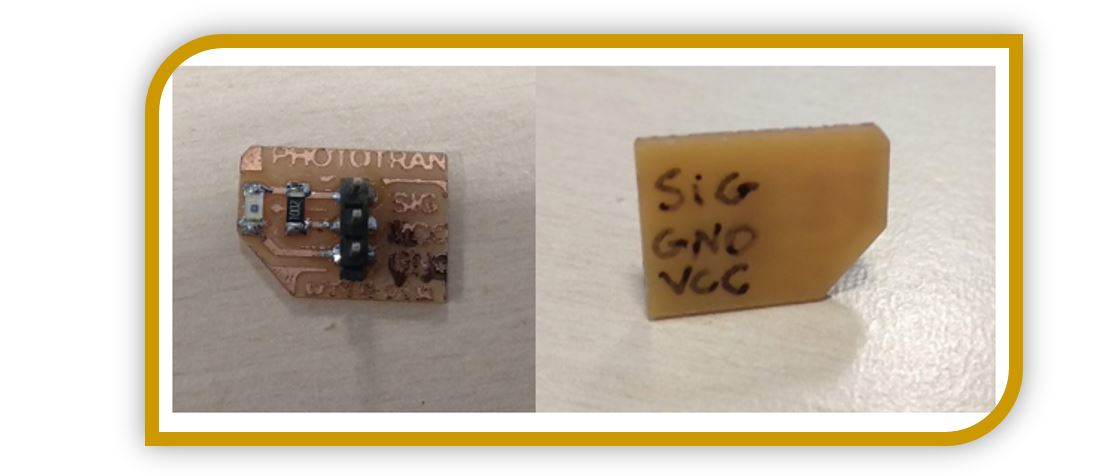
5.- Sensor PT15 (Phototransistor)
As the time of flight sensor I saw that it is a bit complex to use well, I left it for later. So I chose a phototransistor, which may be interesting to me for some possible ideas I have for my final project.
There are two versions of this phototransistor, the PT15 21B and the PT15 21C. I chose the PT15 21B.
The 21B works in the invisible IR range while the 21C works in the visible range.
PT15-21B
https://pdf1.alldatasheet.es/datasheet-pdf/view/229857/EVERLIGHT/PT15-21B/TR8.html
PT15-21C
https://pdf1.alldatasheet.es/datasheet-pdf/view/229857/EVERLIGHT/PT15-21C.html
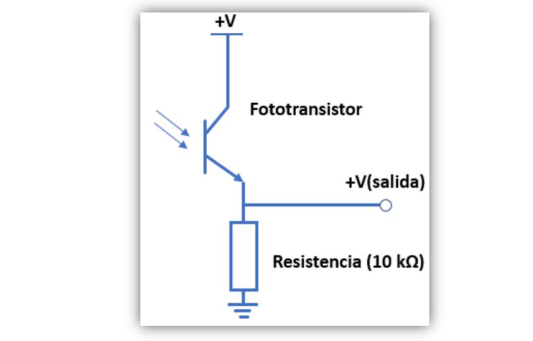
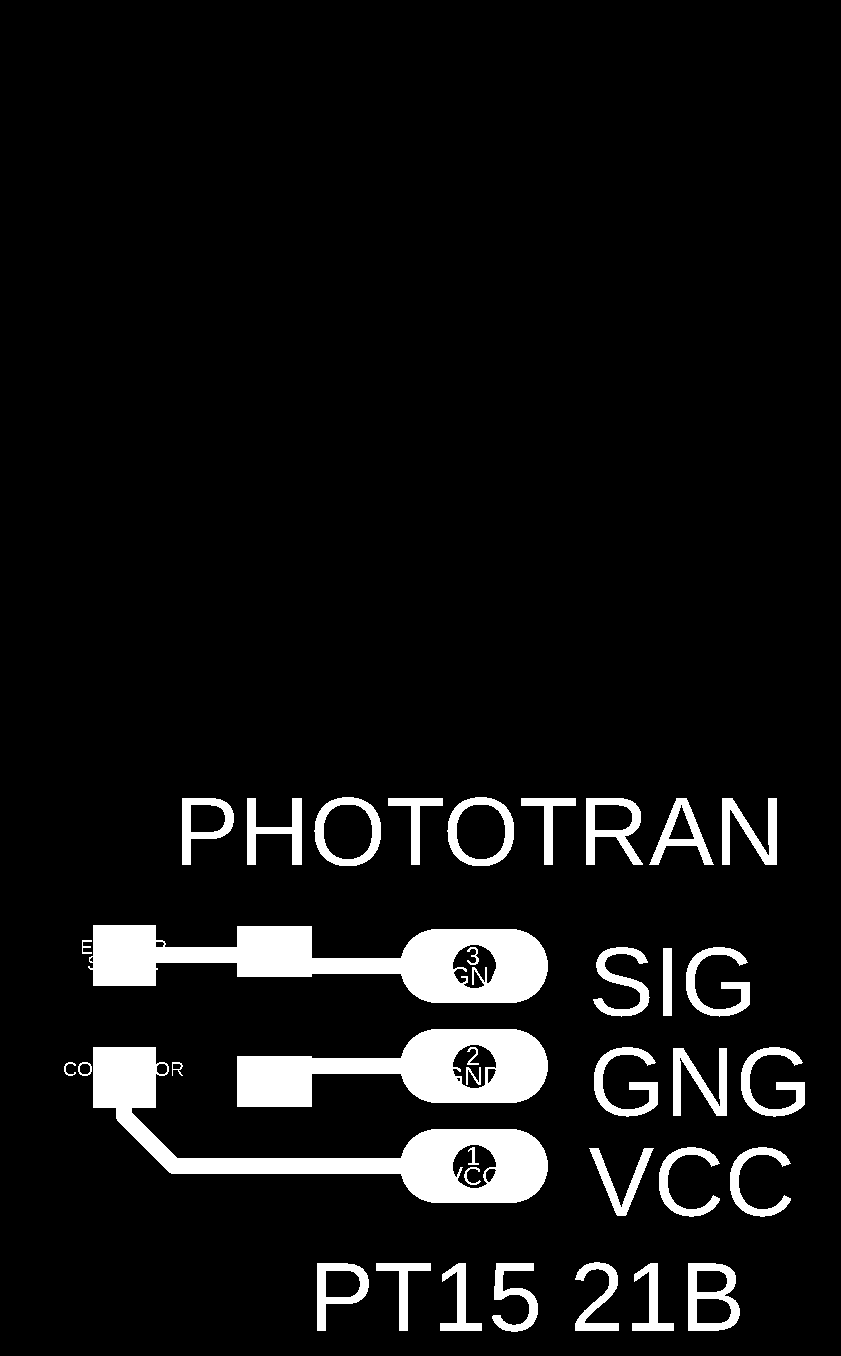
To connect the phototransistor to the board, a 10K resistor is necessary. The emisor is connected directly to VCC. The collector to the resistance and this node to the signal. The other side of the resistor to GND. As seen in the image.
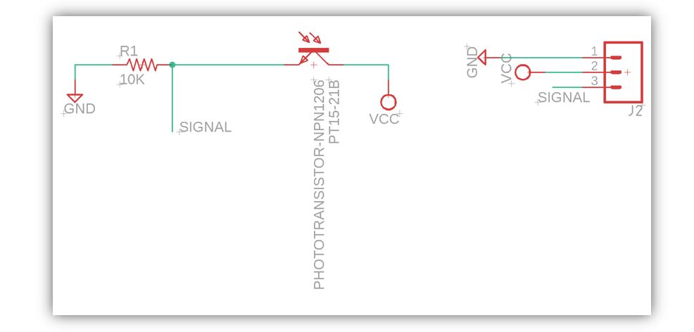
My schematic in Eagle is as follows.
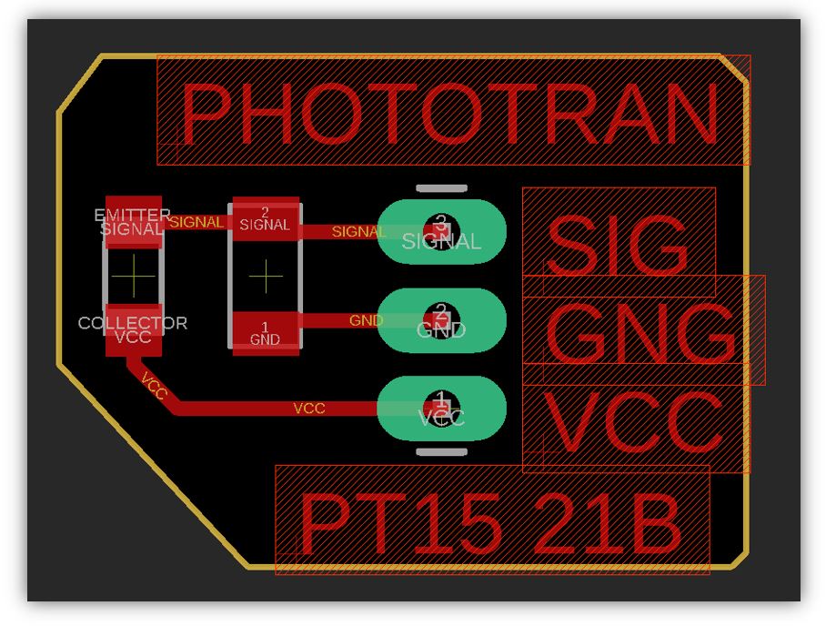
The files for the board milling for the phototransistor are:
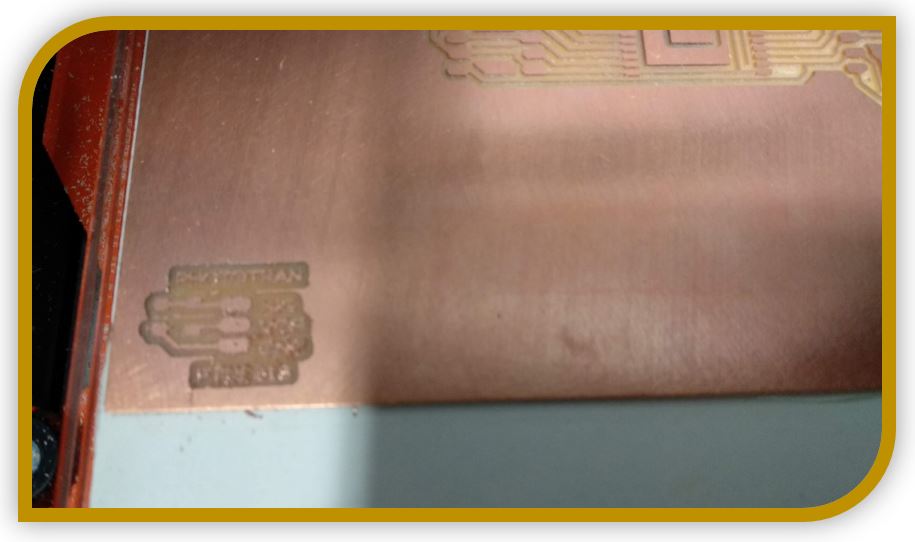
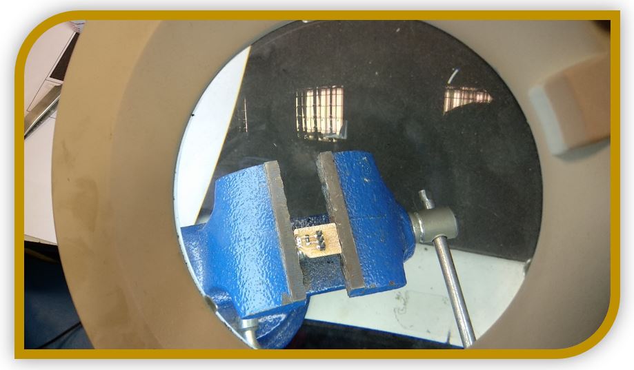
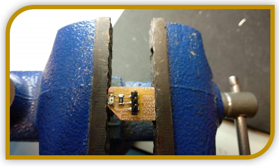
Milling the board:
Soldering the board:
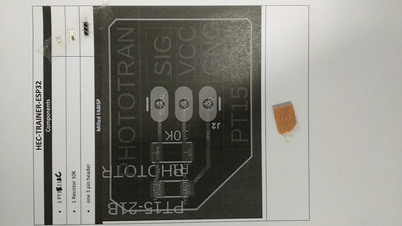
** (NOTE: The board schematic in the list has the names between Vcc and GND changed, but I modified them in the final file and in the rest of the documentation.)
6.-Programming
I am going to work with Arduino ID. In case you need to download:
Arduino ID:(https://youtu.be/mBaS3YnqDaU)
First of all, I need to install the libraries for the microcontroller.
https://dl.espressif.com/dl/package_esp32_index.json
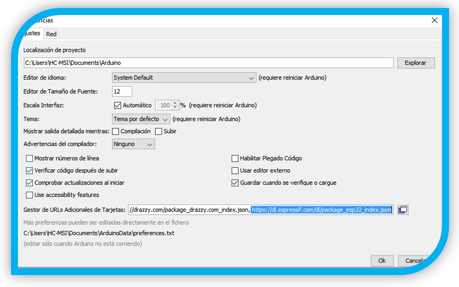
Configure the board manager:
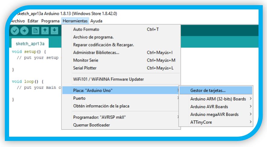
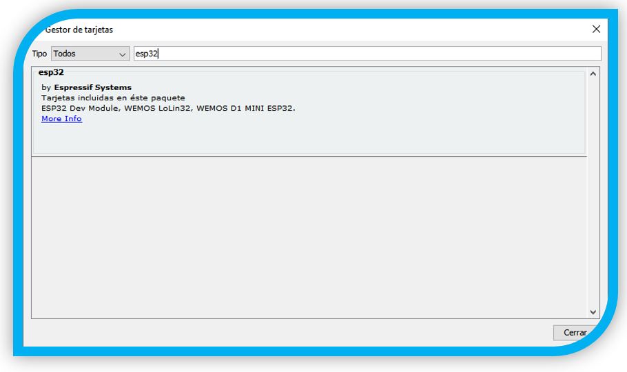
Look for the ESP32 and install.
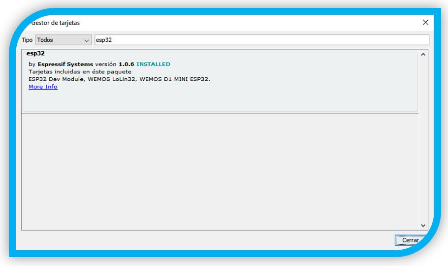
Installed.
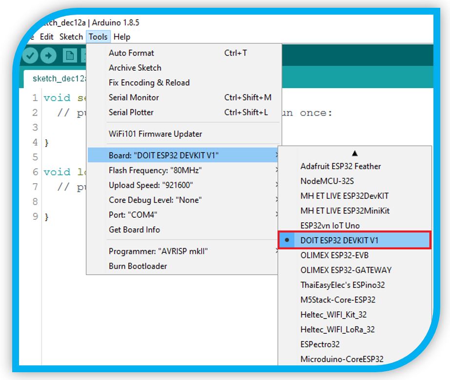
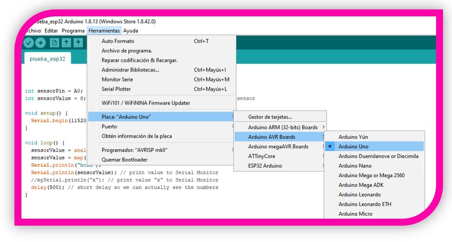
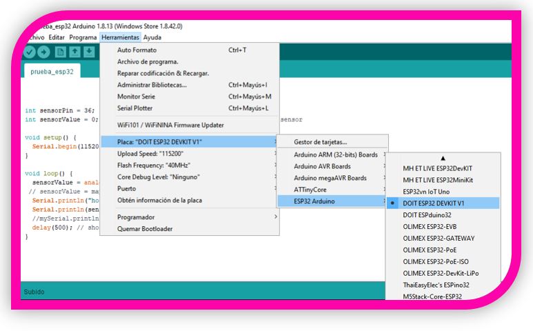
1. Select your Board in Tools > Board
2. Select the Port (if you don’t see the COM Port in your Arduino IDE, you need to install the CP210x USB to UART Bridge VCP Drivers)
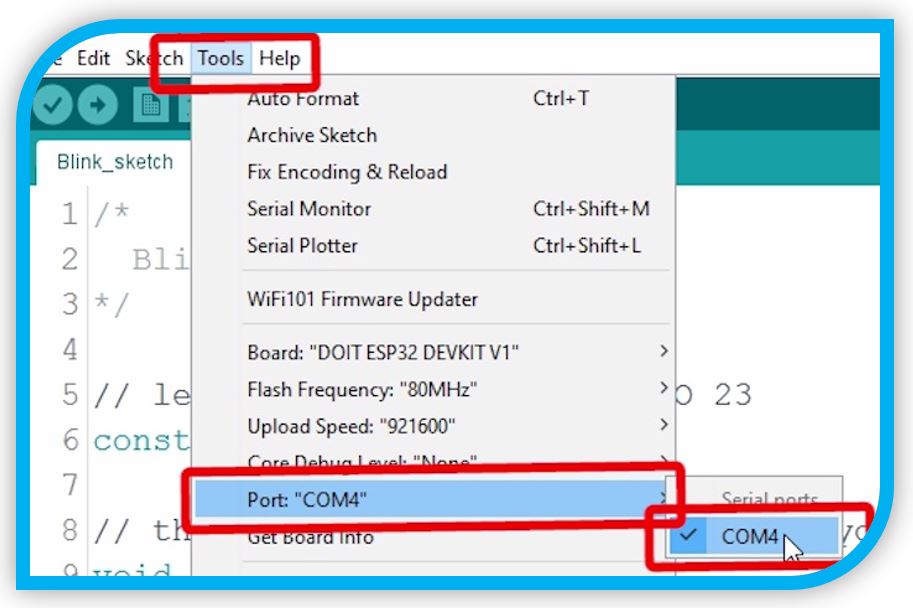
3. Test
WARNING: AT THIS POINT, WHEN I CONNECTED THE ISP-USB CABLE TO PROGRAM, MY LAPTOP WOULD NOT DETECT IT. IT INDICATED TTL232 IN THE DEVICE MANAGER. YOU NEED TO INSTALL A DRIVER.
To install the cable driver, go to the following link:
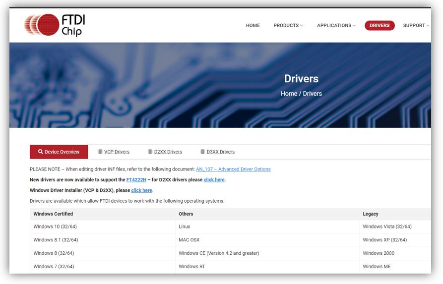
In my case it was to use the link for Windows:

Download and install. Now the UBS port already recognizes the cable.
** This step for cable installation is usually a problem, if you don't realize you need the driver.
To install the tools to be able to program with the ESP32 I have used these two tutorials. Álvaro Macián's may be easier to follow. Although the other is more complete if something else is needed.
https://docs.espressif.com/projects/esp-idf/en/stable/esp32/get-started/windows-setup.html
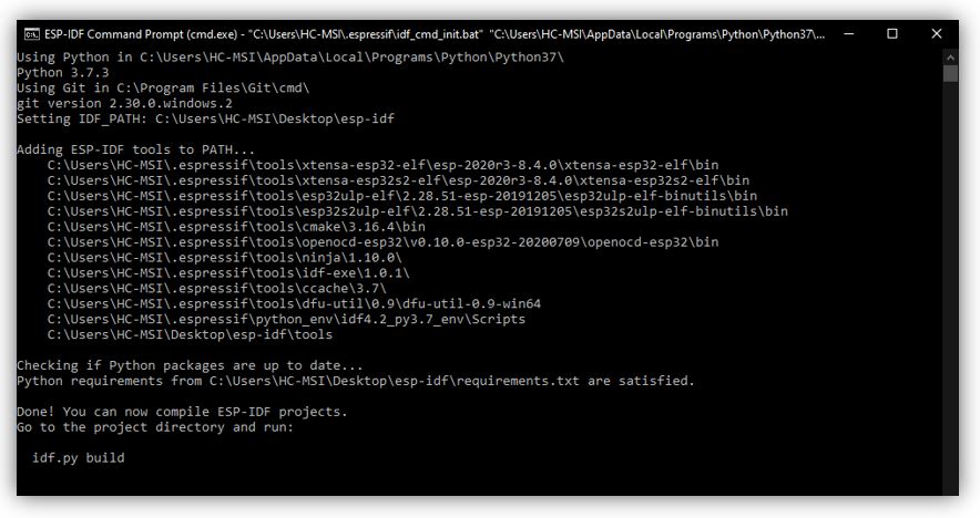
So, I download and install the toolchains:
At the end of installing the command window appears (if it does not exit it can be opened from the folder with the installation)
7.-Testing
Note: as I had problems with the programming of my board, I first tried with Arduino UNO. The problems I had, I comment in the section on testing with ESP32.
Configuration for Arduino UNO:
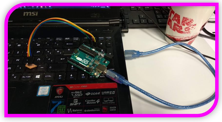
The first step is to open the Arduino ID and configure the board for the Arduino Uno, with its port and programmer.
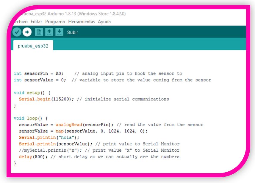
Then load the code of the program you want. To do this, create the code and click to upload.
In this case it is a code that causes a signal to be sent from the signal pin of the phototransistor PT15 to an analogy input of my ESP32 microcontroller.
Configuration for ESP32:
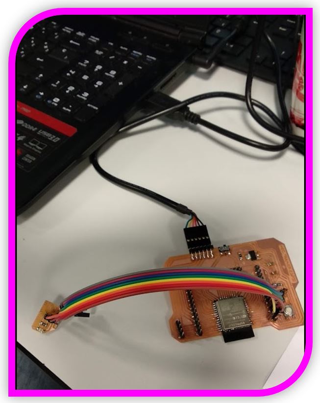
Note: to program the ESP32 you must put the switch in the programming position.
Important note: before burning or uploading the program with the compiler (Arduino ID software in this case), you must press the RESET button on the board. If it is not pressed, it will not connect or it will fail to connect.
PROBLEMS: During this week's board test, I had trouble programming.
I checked the solders, changed the wires, checked the pins, but no luck. The solution was magic.
With my instructor Álvaro Macián, when we tested with my computer in remote connection, it didn't work either. Later he came to the laboratory, tried his computer and it worked the first time!!!!. (It looks like he was lucky because it was his birthday). After this test, everything was working on my laptop ... magic ...
So the first step is to configure the board for the ESP32. (With the library installed, as mentioned in the previous steps)
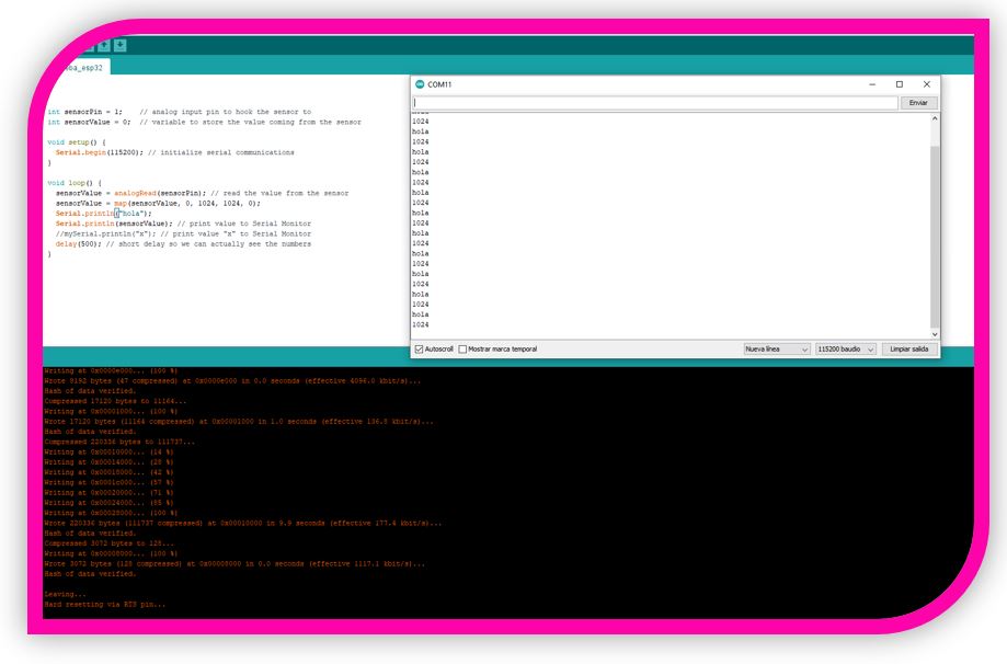
Then I load the same program as with the Arduino Uno, but modifying the pins according to this microcontroller. I upload the program and when I open the monitor, I get my sensor reading.
8.- Upgrades
With the first two readings with my program, I obtained values with a very strange "scale", although they made sense depending on the sensor captures light or shadow.
So, I loaded the following program with some modifications to show me a scale with output from 0 to 100%.
Const int analogInPin = 34;
Int sensorValue = 0;
Void setup() {
Serial.begin(9600);
}
Void loop () {
sensorValue = analogRead(analogInPin);
sensorValue = map(sensorValue, 0, 4095, 0 ,1000);
serial.print((float)sensorValue/10);
Serial.print(“%”);
Delay(100)
}
9.- Experience and conclusions of the week
A week about which I learned a lot, although I had problems with welding again.
It might also be a bit hard for me, because I am not very used to programming and handling the inputs that I have used in Arduino, it has been all new for me.
But I'm happy with the results and getting it to work.
“What went wrong”: I had problems with the solder so I had to check the board. I thought about using the VL530X (Time of Flight) because I found it interesting, but I found it a bit complicated. Change to PT15.
“What went well”: The connection with the PT15 and the tests to measure the light are good, it is a good sensor to control the brightness.
“What will you do differently next time”: With more time, I would try the VL530 (Time of Flight) because I have seen that it has applications for 3D scanning that I found very interesting.
10.-FILES
Doc Sensor VL530X
Doc Sensor Phototransistor
ESP32 HEC-BOARD TRAINER
Phototansistor Board
Code Sensor Test
Eagle Files (HEC-TRAINER-ESP32 & PhototransistorBoard