WEEK 14
- 1.- Introduction
- 2.- Teamwork
- 3.- Creating an Android interface with ESP32 + Bluetooth:
- 4.- Understanding the code:
- 5.- CREATING THE ANDROID APP: MIT App Inventor 2:
- 6.- Problems and solutions:
- 7.- ESP32 web server. Using WiFi communication with ESP32:
- 8.- Dowloads:
- 9.- Experience and conclusions of the week 14:
Interface and Application Programming:
Teamwork
Individual Assessment
Fab-Weeks
Are you looking for my assignments?
Links and notes
more information:
Week 14: Interface and Application Programming
1.- Introduction:
In this week I am going to try a set of options to know how the interfaces behave using the Bluetooth of the ESP32 and using the WiFi server with the ESP32.
The idea is to see which one can best be adapted for the development of the control for my final project dispenser.
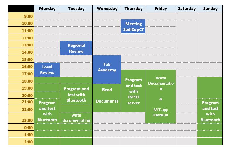
This week has been a bit hard, but I managed to connect with the Regional Review, although I speak in Spanish because my brain was a bit cloudy.
2.- Teamwork
If you want to know the group assessment of this week, click on the image of SediCupCt.
3.- Creating an Android interface with ESP32 + Bluetooth:
The idea of this section is to test Bluetooth communication to create an Android interface. It will serve to evaluate the possibility of using this communication and interface model for my final project, if it is useful.
I am going to use an example interface that I have found to drive a temperature sensor, but I am going to modify my code to use the phototransistor that I use past weeks. I can also control a led with this same application.
4.- Understanding the code:
To understand how Bluetooth programming works, I am going to explain the example with the temperature sensor. From this information I started to create the program for my phototransistor.
In order to use the code well, you first need to install the necessary libraries to control the ESP32 and the BLE server.
*** Important: do not change the UUIDs, otherwise the Android application created with MIT Inventor must also be modified so that communication is possible.
Sensor:
■ You have to define the reading pin for the sensor, in this case the GPIO pin 27. (#define ONE_WIRE_BUS 27).
■ An instance must be created to communicate the device of a bus. OneWire oneWire (ONE_WIRE_BUS);
■ Then pass the oneWire reference to a sensor object. “DallasTemperature sensors (& oneWire);
■ Create BLECharacteristic pointer for Bluetooth communication. (BLECharacteristic * pCharacteristic;)
■ Create a connected or not connected control variable. (bool deviceConnected = false;)
■ Create a variable to save the temperature so that it can be sent to the client, in this case to send to the Android application. (float temperature = 0;)
■ Finally, configure the pin for the GPIO 26 led indicator. (Const int ledPin = 26;)
Setup:
Initialize the port for a baud rate of 115200. (Serial.begin (115200);).
■ Set the pin for the led as an output. ((pinMode (ledPin, OUTPUT);)
■ Initialize the sensor (Sensor.begin ();)
BLE server:
■ Create the server. (BLEServer * pServer = BLEDevice :: createServer ();
■ Set callback for the server. (pServer-> setCallbacks (new MyServerCallbacks ());). And for the feature (pCharacteristic-> setCallbacks (new MyCallbacks ());).
■ If the connection is successful, the onConnect () function is called and the deviceConnected variable is changed to true, to indicate that it has connected.
void onConnect (BLEServer * pServer) {
deviceConnected = true;
};
■ When the client disconnects, the onDisconnect () function is called and the deviceConnected Boolean variable is set to false to indicate the disconnection.
void onDisconnect (BLEServer * pServer) {
deviceConnected = false;
}
BLE service:
■ A service has to be created with the defined UUIDs. BLEService * pService = pServer-> createService (SERVICE_UUID);
BLE characteristics:
Two characteristics are created for this servic:
■ pCharacteristic = pService-> createCharacteristic (CHARACTERISTIC_UUID RX, BLECharacteristic :: PROPERTY_WRITE);
■ Characteristic * pCharacteristic = pService-> createCharacteristic (CHARACTERISTIC_UUID_RX, BLECharacteristic :: PROPERTY_WRITE);
The TX feature is responsible for sending the values to the client, in the example it will send the temperature values every 5 seconds.
The second characteristic, RX, is responsible for receiving the new values for the client. For this example, it receives the on and off commands to control the output. This feature has the property of enabling writing and has the onWrite () callback function assigned.
void onWrite(BLECharacteristic *pCharacteristic) {
std::string rxValue = pCharacteristic->getValue();
if(rxValue.length() > 0) {
Serial.print("Received value: ");
for(int i = 0; i < rxValue.length(); i++) {
Serial.print(rxValue[i]);
}
// Turn the LED ON or OFF according to the command received
if(rxValue.find("ON") != -1) {
Serial.println(" - LED ON");
digitalWrite(ledPin, HIGH);
}
else if(rxValue.find("OFF") != -1) {
Serial.println(" - LED OFF");
digitalWrite(ledPin, LOW);
}
}
}
When the server receives a new value, it calls the onWrite () function and writes a new value to the server characteristic. The value is stored in the variable rxValue. Then, according to what was received, while the command is on or off, the LED turns on or off.
if(rxValue.find("ON") != -1) {
Serial.println(" - LED ON");
digitalWrite(ledPin, HIGH);
}
else if(rxValue.find("OFF") != -1) {
Serial.println(" - LED OFF");
digitalWrite(ledPin, LOW);
}
Start BLE:
After creating the server, service and assigning the characteristics, start the BLE service:
pService -> start();
And it begins to advertise so that the client can find the server.
pServer -> getAdvertising() -> start();
Loop()
In the loop it is constantly checking if the device is connected or not. If the device is connected, the following statement is true. A new reading is then taken from the sensor and stored in the temperature variable.
if(deviceConnected) {
// Measure temperature
sensors.requestTemperatures();
// Temperature in Celsius
temperature = sensors.getTempCByIndex(0);
// Uncomment the next line to set temperature in Fahrenheit
// (and comment the previous temperature line)
//temperature = sensors.getTempFByIndex(0); // Temperature in Fahrenheit
// Convert the value to a char array
char txString[8];
dtostrf(temperature, 1, 2, txString);
// Set new characteristic value
pCharacteristic->setValue(txString);
// Send the value to the Android application
pCharacteristic->notify();
Serial.print("Sent value: ");
Serial.println(txString);
By default the temperature is sent in degrees Celsius. You can comment on the following:
temperature = sensors.getTempCByIndex(0);
and stop commenting on the next line to get the reading in Fahrenheit.
//temperature = sensors.getTempFByIndex(0); // Temperature in Fahrenheit
Finally, before sending the value for the connected client, you have to convert the float variable to an array of characters using the dtostrf () function.
dtostrf(temperature, 1, 2, txString);
then you have to set the new characteristics with the new value and notify the customer.
// Set new characteristic value
pCharacteristic->setValue(txString);
// Send the value to the Android application
pCharacteristic->notify();
This process is repeated every 5 seconds.
delay(5000);
*** IN SUMMARY: when a client connects to the ESP32 server, it sends a new temperature read every 5 seconds. When a client writes to the RX feature the ON or OFF command that controls the LED.
5. CREATING THE ANDROID APP: MIT App Inventor 2:
This software is free to use and aims to be simple and intuitive when creating Android applications. You don't need to be a programming or design expert to build useful applications.
You don't need to install anything to use this software because it is cloud-based. So you can build applications directly in the browser. It only requires an internet connection.
The workflow with this software is as simple as selecting and positioning the different components on the Smartphone screen.
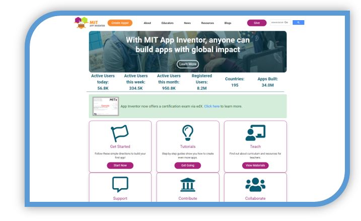
To access MIT App Inventor 2, go to the following link:
The first thing to do is press the orange button to create an application.

To access the creation of the process, you will ask to use a Google account and follow the steps to log in. Then the work pane will open.
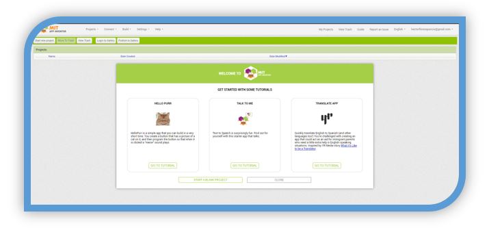
For the test with my sensor, I am going to open a created template and I am going to modify it based on my photoelectric sensor.
To do this: Projects -> Import -> import from my computer -> I choose the aia file and then press ok.
** (NOTE: The .aia file is a source code file created by MIT App Inventor for building applications. Contains the source code blocks for an application project under development.)
The design area for the application then opens. In it you can add buttons, text, images, sliders, etc. And it allows to change the general appearance of the application.
In the Designer area, there are several sections:
■ Palette: contains the components to create the application layout, such as buttons, sliders, images, labels, etc ...
■Viewer: This is where you drag the components to create the appearance of the application.
■ Components: shows the different components added to the application and how they are organized hierarchically.
■ Media: this part shows the imported media such as images or sounds that you want to add to the application.
■ Properties: This is where component properties such as color, size and orientation are selected.
As mentioned, once the application test template is loaded, it can be modified by adding more elements or removing existing elements. The characteristics of the included elements and their visual appearance can also be modified.
Components & Text labels.The first one is "VALUE" which is only invariable text, to indicate that a value will be displayed here. The second is "..." which is the text where the readings taken from the sensor will appear. Images: To add an image to the viewer, go to Palette -> Image and drag the image symbol where you want to put it in the application. From its configuration part, it is possible to indicate which image is going to be put and the other parameters. Buttons: In this application you can see the button that turns the led on and off and the data reading and another to connect by bluetooth. To add buttons, it is similar to adding images, just drag on the application's viewer. Then in the part on the right, in properties, you can make the modifications you want.
List selector: "ListPicker": The ListPiker is not visible in the viewer, but it is called when the connect button is clicked. This button is usually necessary in this type of application, to know if we are connected.
Non-visible components: In this example, two non-visible components are used, one of them the clock and the other the Bluetooth LE.
Inventor 2 software does not support BLE by default. It must be added or viewed from the extensions area of the User Interface.
This has been an introduction to the designer area:

Now, you have to click on the blocks button to start working in the blocks area on the relationship of all the elements that make up the application.

This section, Blocks, contains the application logic. This is what allows you to create custom functionality.
So when you press the buttons, it really does something. The logic of the application is created by combining different logic blocks. This is what makes the app define button functionalities, search for nearby devices, connect to BLE devices, etc.
Defining UUID:
The first thing to do is define the UUID blocks, to establish the RX - TX service.

These UUIDs should match the ones used in the Arduino IDE. If you want to use other UUIDs, you have to modify them in both parts to make it work. To generate UUID, you can use the generator from the following link:
https://www.uuidgenerator.net/
Listing and connecting to a BLE device.
The next set of blocks is responsible for listing, picking and connecting to a BLE device.
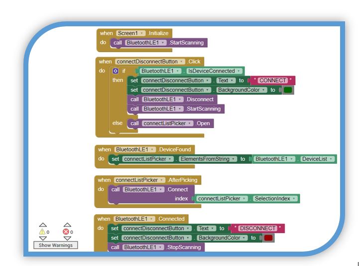
This set also changes the appearance of the button depending on whether the application is connected to a BLE device or not.
These blocks are usually necessary blocks, because with BLE applications you always need a way to list and connect to a BLE device. However, there are different ways to do it, for example, you can have two buttons: one button to connect and another to disconnect.
Receiving Notifications:
The sensor characteristic (RX characteristic) has to have the notification property enabled to receive data every 5 seconds.
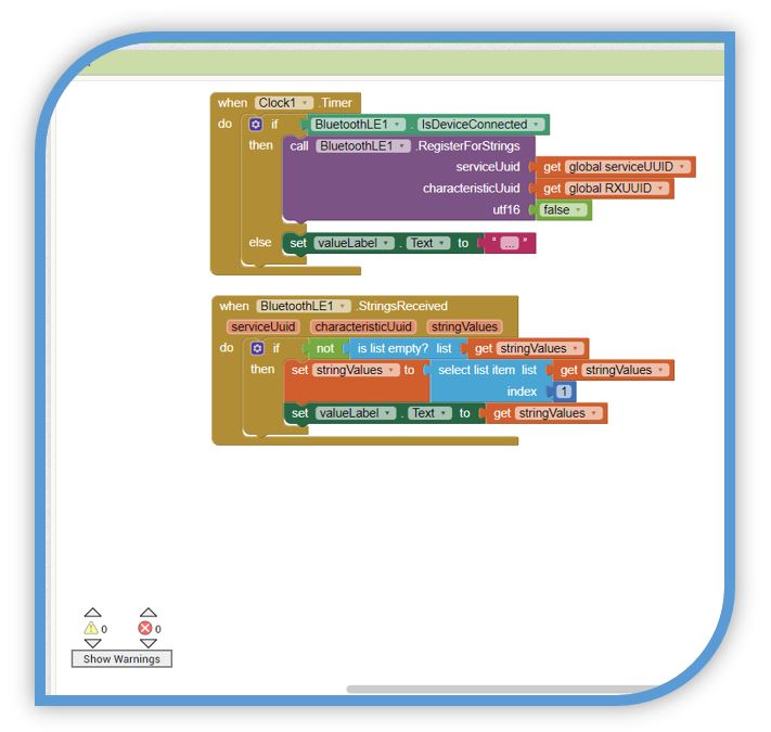
The first block starts the RX characteristic to receive new values or sets the temperature value to "...", if the client disconnects. The second block receives the message sent from ESP32, saves it in the stringValues variable and displays it in valueLabel.
**** Note: this code block works whether you send the temperature or any other value. So there is no need to change any of these blocks, even if other values are being received from ESP32.
Shipping Commands:
With the following block, the ON or OFF is sent to activate the commands of the ESP32 outputs.
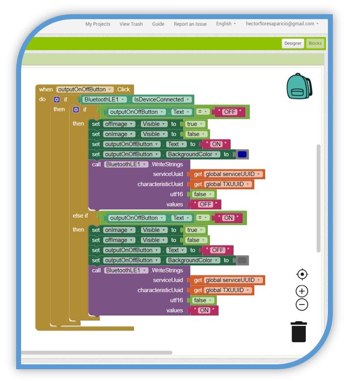
Basically, to send commands to the ESP32, write “ON” or “OFF” in the TX feature. This is what happens when you click the "ACTIVATE" button:
■ Sets the image with the lamp on as visible;
■ Set the image with the lamp OFF to invisible;
■ Change the appearance of the button: set the text to "OFF" and change the color to gray;
■ Finally, write “ON” in the TX characteristic.
If you want to send other commands to control other outputs, you just need to add more buttons to the application layout. Then, depending on the button pressed, write different messages about the TX feature. After that, you just need to add conditions to the Arduino IDE Code, for the ESP32 to do what you want.
NOTE:
You can test the application on your smartphone while editing in real time. The MIT AI2 Companion App needs to be installed on the smartphone. To do this you have to go to the Google Play Store and search for "MI AI2 Companion" and install.
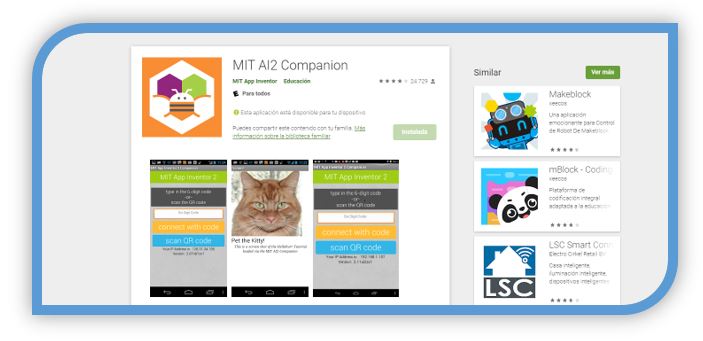
When you open the application, the following screen will be presented.
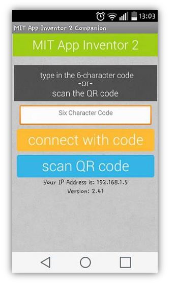
To test the application, in the MIT App Inventor 2 software, click Connect -> AI Companion:

A QR code like the one in the following figure should appear:
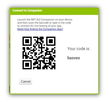
On the Smartphone you can read the QR code, then open the link and download the application created. Once downloaded, all you have to do is install it and accept the permissions. There is also the option to see the modifications of the apk in real time if the add-on for PC is used.
VIDEO BLUETOOTH INTERFACE ESP32
6.- Problems and solutions:
With the Bluetooth connection I have had several problems when connecting with my smartphone device.
■ Before doing anything, the first thing I did was try to connect my ESP32 with the laptop's Bluetooth.
The ESP32 was connected correctly and with the screen of the Arduino serial monitor I could verify that the program started to work, acquiring values from my light sensor. With this step I verified that the Bluetooth of the ESP32 works and the program code also.
■ The next step was to look for possible solutions for the Bluetooth Low Energy connection. Then I saw that other users needed to add a permission line in the MIT app Inventor Block diagram.
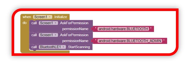
With this, when you start the application you can ensure that you have Bluetooth permissions. But it didn't work for me.

■ This didn't work for me either. I also read that with some Bluettoth libraries for the MIT application Inventor extension, depending on the Android version of the smartphone, it can give problems.
I tried a couple of them and eventually got one that connected. The Bluethooth library that worked for me for this example was (BLE-with-new-ConnectDevice.aix). It is inside the archives of the Bluethooth libraries.
*** NOTE: BUT ALWAYS ACTIVATING THE LOCATION PERMISSION FROM THE ANDROID APPLICATION MENU OF THE SMARTPHONE.
7.- ESP32 web server. Using WiFi communication with ESP32:
With this example, also mentioned in the previous week, about communications, I am going to test an interface by WiFi connection through a server with ESP32.
In summary: With this example I am going to connect my ESP32 to create a web server to control two LEDs.
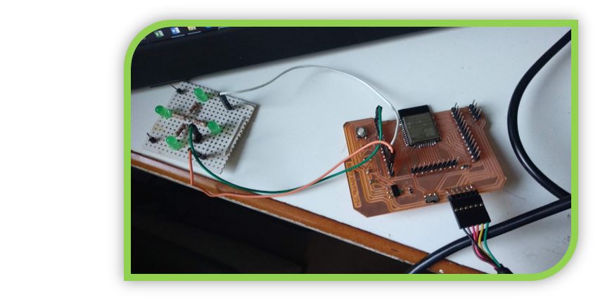
■ LEDs will go to GPIO26 and GPIO27
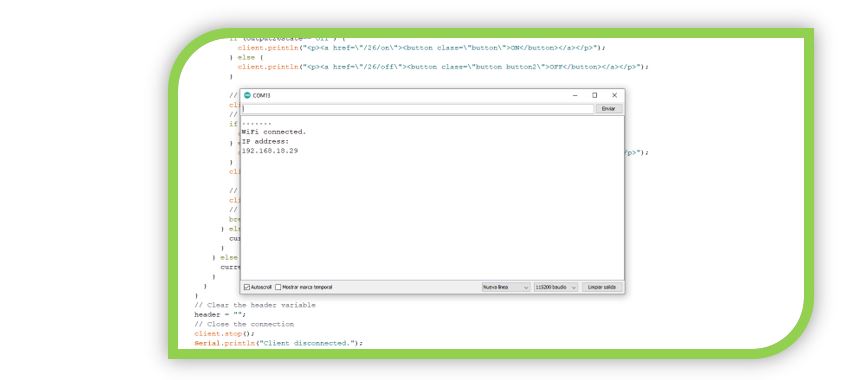
■ To access the server, just use the IP from a browser on the local network
THE CODE
The first step is to load the WiFi library.

Then you have to declare the variables with the credentials for the WiFI network to which the ESP32 is going to connect.

You have to indicate the port

A variable is also needed to store the HTTP request

Then you have to indicate the variables for the LEDs, the status and the output pins.
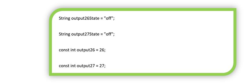
A counter to know the time

Create a timeout

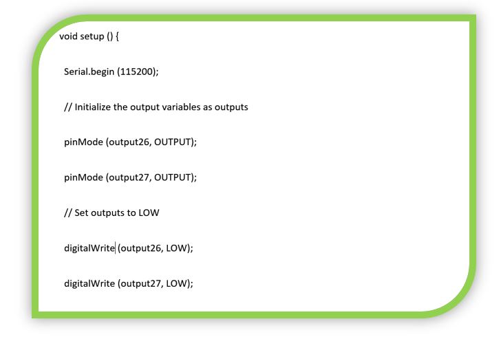
In the setup, the communication speed (in baud) is indicated and the pins are initialized
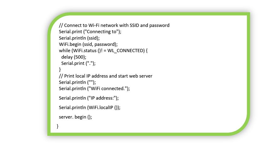
In addition, you have to start the WiFi connectivity and assign the IP for the local server with the ESP32
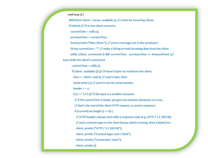
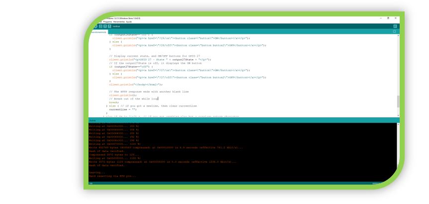
Now comes the part of the code that runs in a loop. In blue it is the code corresponding to the client connection with the server.
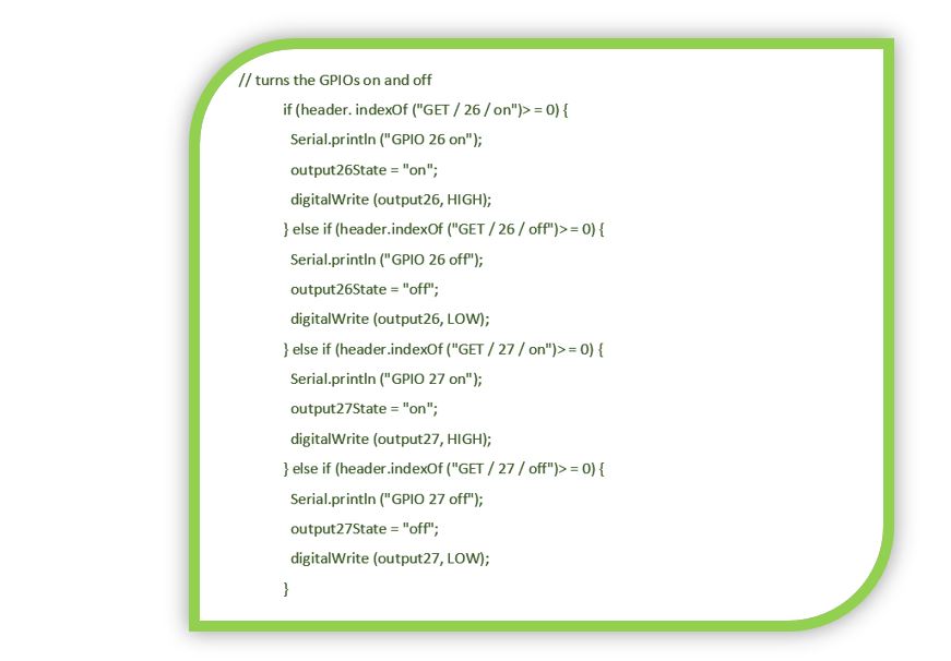
The part of the code in green color refers to the code sequence that operates the buttons to turn the LEDs on and off from the server.
With the code in orange, all the lines referring to the programming of the web environment are shown, for the visual aspect of the buttons, indicators, the text that should appear ...
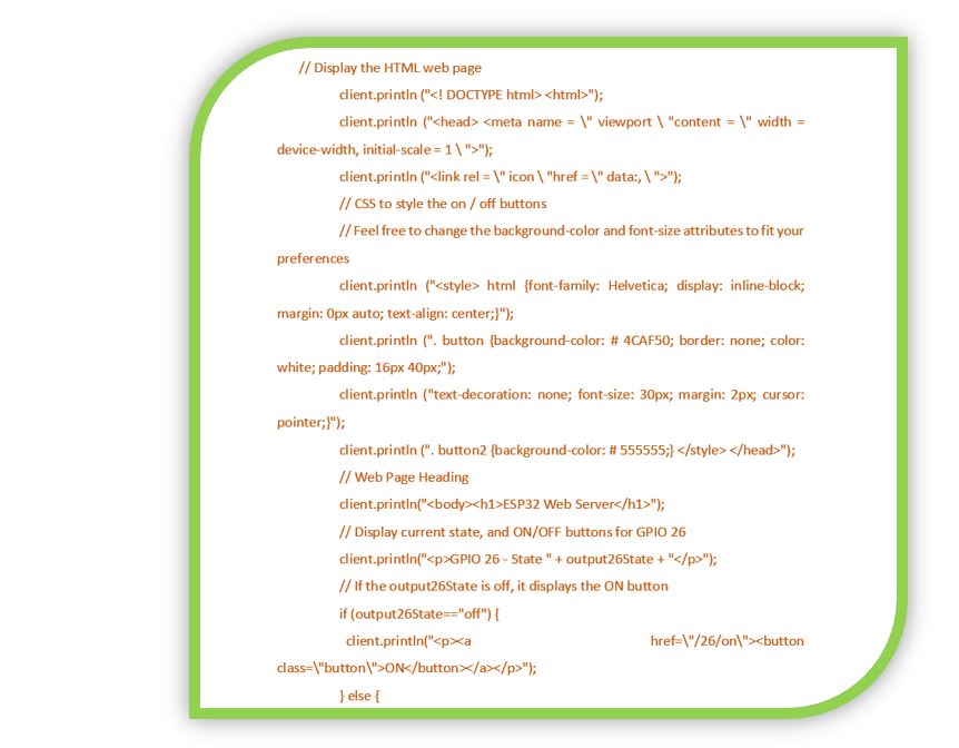
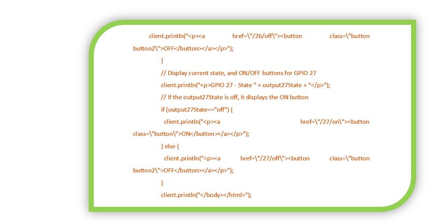
The code for the server shutdown is indicated in black.
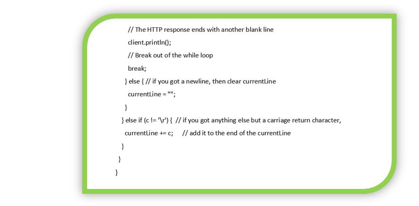
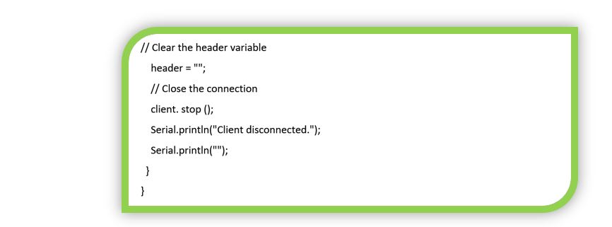
Finally, the connection is closed and the variables are cleaned
I connect the LEDs:
I upload the program:
From Aruino IDE I open the serial monitor to know the IP with which to connect from the browser:
Connection video
8.- FILES
Bluetooth interface codeLibraries Bluetooth MIT INVENTOR
Web Server Interface ESP32
MIT INVENTOR file ESP32
9.- Experience and conclusions of the week 14:
Hard week because of work and because I had a wedding on Saturday.
Except for those two reasons, with Bluetooth communications I was a bit slow when trying the MIT Inventor app, because I did not know it and I was learning to handle it. But the result was good.
I thought about using this type of communication and application to control my automatic dispenser, the final project. But comparing to using WiFi, I think using a web server can be more multifunctional.
“What went wrong”: I had to try several Bluetooth libraries. Depending on the device and the version of Bluetooth it may or may not work properly.
The Bluethooth library that worked for me for this example was (BLE-with-new-ConnectDevice.aix). It is inside the archives of the Bluethooth libraries.
“What went well”: When you connect, the application works very well. It is also a free source.
“What will you do differently next time”: I would try some developer of visual styles for websites. So you could make very visual and eye-catching control environments.
