The design
Principle
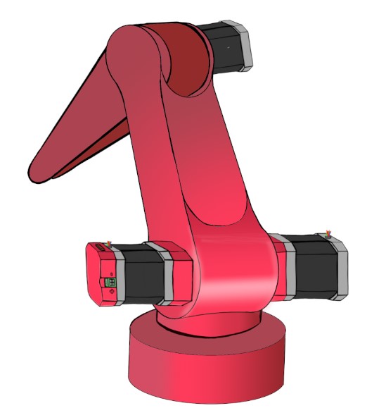
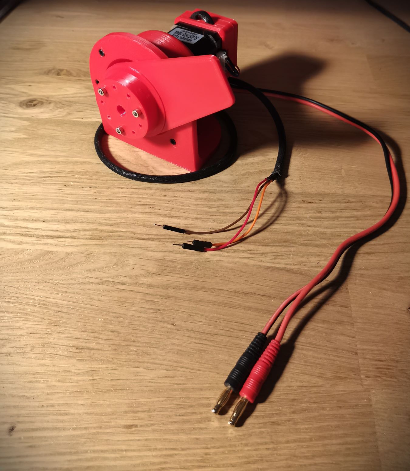
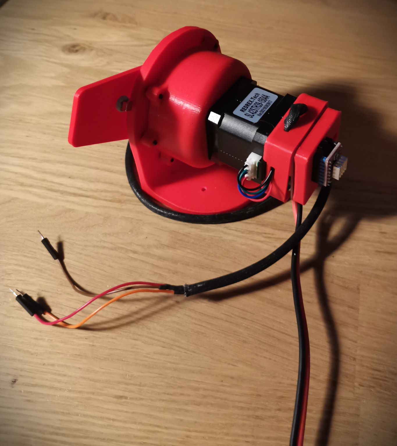
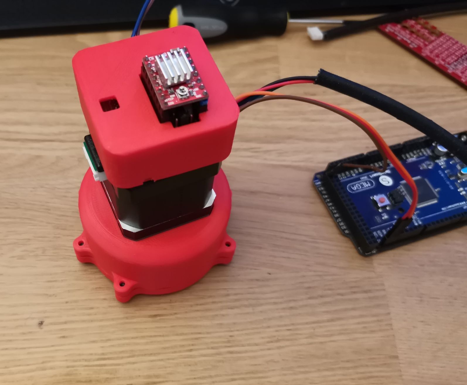
My final project is a small stepper motor connected with a 3D printed cycloidal reducer. The whole thing is controlled by a custom electronic board. This project can be use by any hobbyist to bring powerful servo joint into prototypes.
For instance, it can be used in a robot arm. Or even, it may become a 4th axis on a CNC machine !

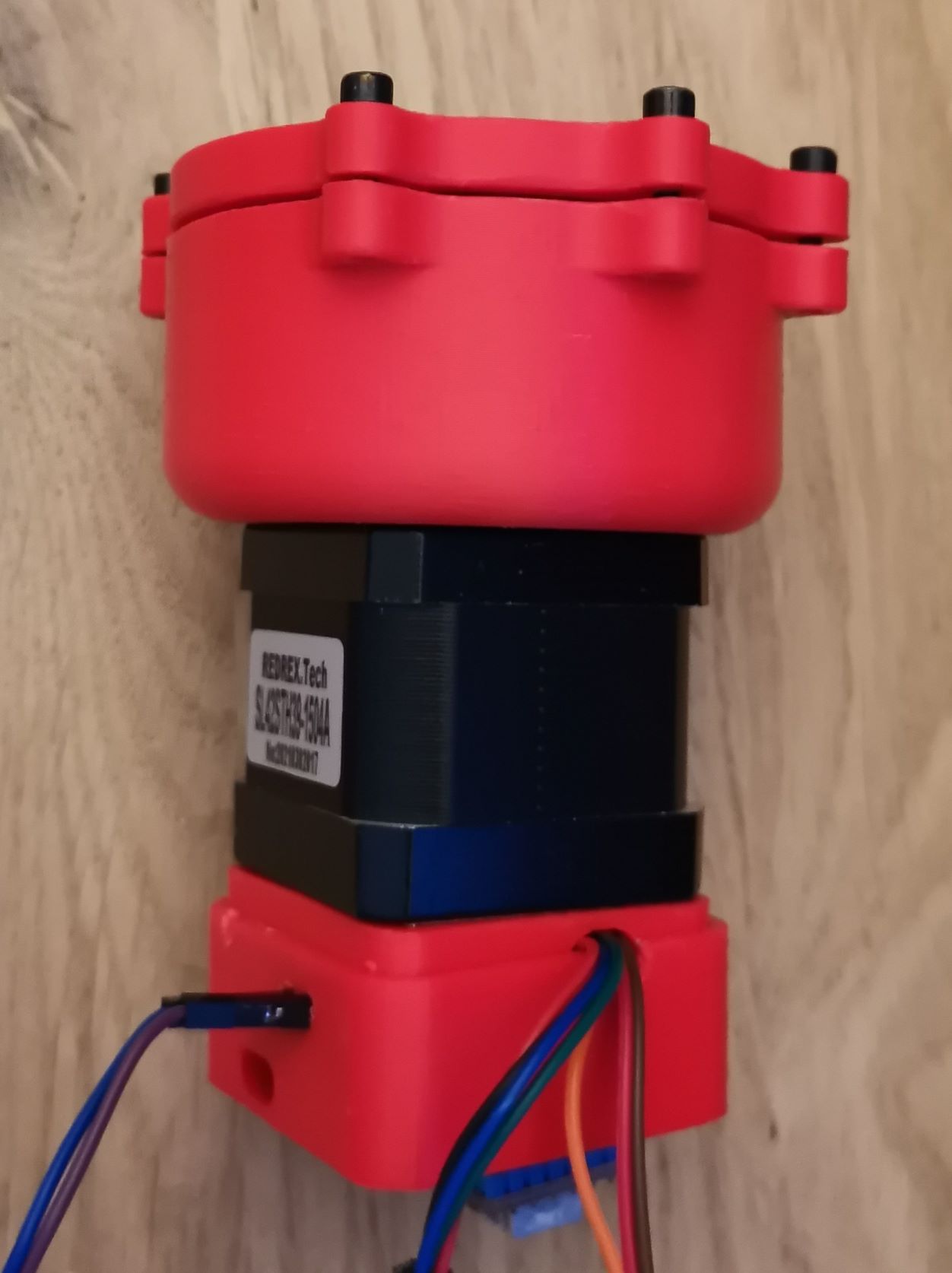
As you can see, there is 3 main part on this project. At the top, there is the control board. The board is powered by an external 9-12v DC power supply. Just below the board there is the stepper motor. I used a NEMA17 in my final project, but you’ll see that I tested designs on both of them. Finally, there is the reducer à the bottom. The aim of the reducer is to reduce the rotational speed in favor of torque. In theory, this project should be able to supply up to 5N.m of torque. In practice, some adjustment is necessary because the teeth of the reducer slips because of mechanical backlash issues. Backlash can be limited by adjusting design dimensions.
Processes that will be used
I used lots of different processes to discover what fabrication workflows was the most efficient. Finally, I come up with the solution below. However, this depends on the material’s availability and on the machines you have. Fortunately, there are lots of alternatives methods.
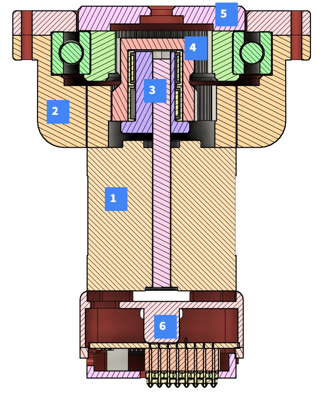
As you can see below, I divided the project into 6 different parts.
- Nema17 Stepper motor
- Outer casing
- Input shaft with excentric wave generator
- Single Planetary gear
- Output shaft
- Motherboard
Obviously, the nema17 stepper motor is bought or can be recycled.
| Parts | Planned process | Alternative |
|---|---|---|
| Outer casing | 3D printing (FDM) | CNC Milling |
| Input shaft | 3D printing (DLP/SLA) | 3D printing (FDM) |
| Planetary gear | 3D printing (DLP/SLA) | 3D printing (FDM) |
| Output shaft | 3D printing | Laser cutting |
| Motherboard | CNC Engraving | Chemical abrasion |
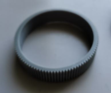
Some parts are also laser cut, just like this one :
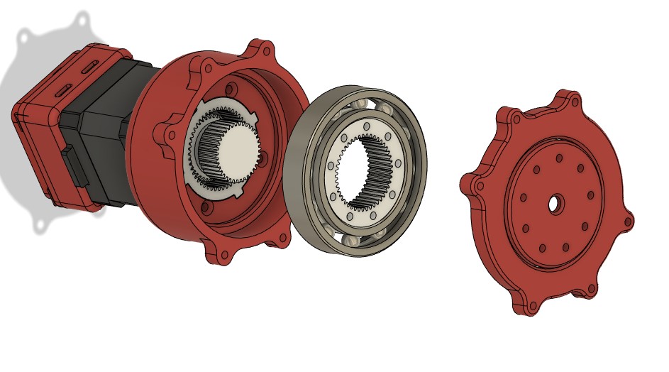
Here is an exploded view of the design :
Part description
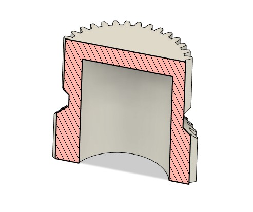
Casing
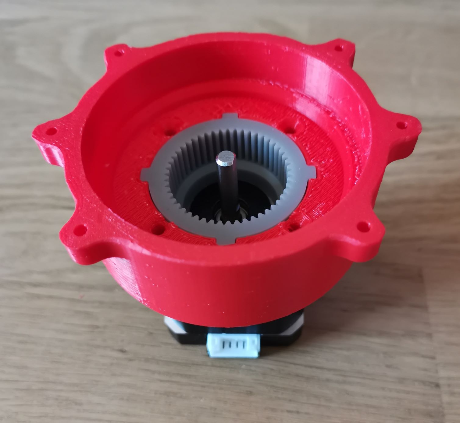
On of the most important part of the design is the Casing. This part will handle all the mechanical stress for the others. Because the gearing and the motor are brittle, we have to take the force using this big part.
Actually, the casing is made of two parts. One is printed using FDM. The other is printed using SLA printing. Please check week 6 SLA or week 6 FDM if you want to know more about it.
As you can see, the grey part, made out of resin is placed before the red one. Four screw are then used to fix everything with the stepper motor.
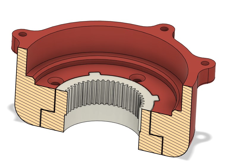
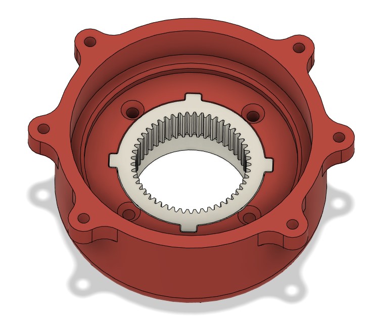
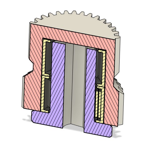
As you can see I tried to demonstrate that SLA printing and FDM printing are two complementary fabrication methods. You can create very strong parts with FDM, I used this for the casing. And at the same time you can be really precise with the SLA/DLP Printer. So you can create very cool gears and stuff. Here the teeth have a pressure angle of 25° wich mean they can handle lots of force. However, The resin you’re using is very game changing. I used the ABS-like resin from phrozen.
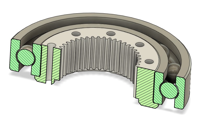
Outer shaft
The outer shaft is responsible for the output power. It need to deliver torque directly but as it will be attached to someting else, we need to handle other forces using a big ball bearing.
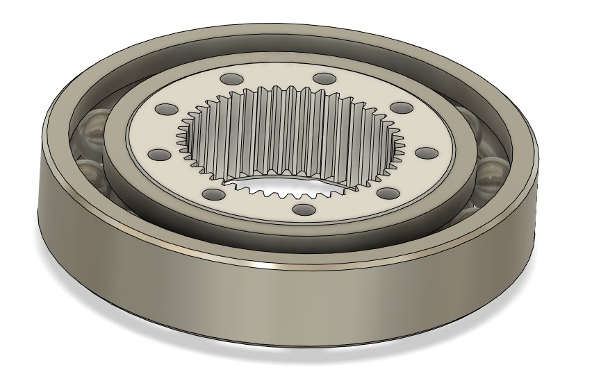
The outer shaft has a very particular form to be easily mounted on the bearing. Because the bearing is then mounted in the casing using lot of force.
Cameshaft
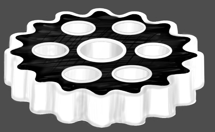
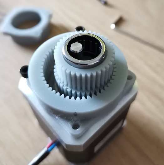
The inner gear is responsible for the reduction ratio. This gear will orbit in the design to divide by 20 the speed of the outer shaft. However, he will also multiply the torque by an order of 20.
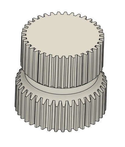
As the design is really compact I had to make it hollow to fit the needle bearing and the exentric shaft inside. As a result, this part deform a little bit when too much torque is required. The teeth slips because of that. I need to redesign this thing to adjust the backlash and increase the overral torque
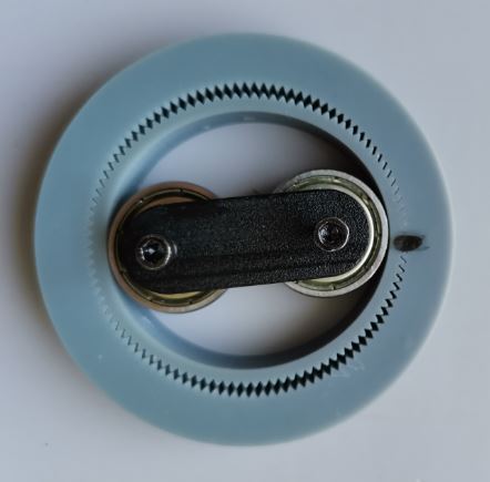
Here goes th excentric shaft ! Little wobly thing… This little bearing needs to be very compact and can handle big radial load.
Fusion 360 Archive
The whole design is accessible on Fusion360 or by clicking on the button below
Project Research
Cycloidal reducer
I have done a lot’s of research on the cycloidal drive. This pinciple is amazing, but I didn’t wanted to copy something existing. I prefer comming with my own design so I tried to experiment new things with that.
Here is the basic principle of cycloidal drive :

Those kind of reducer are pretty cool because :
- 3D printing friendly
- Compact
- Funny to work with
But also :
- Difficult to design
- Don’t last long
- Noisy
I tried to replicate an opensource project available online :
The biggest problem I got by 3D printing this reducer was the fact that the PLA or PETG hasn’t a very good friction ration. So I tried to find a better material that can be 3D printed.
I found a material suitable for this application : POM
POM has a very low friction coefficient and is very resitant against :
- Loads
- Chemicals
- Temperature deformation
This material is often used for plastics gear in copy machine or toys mechanism. So I give him a try.
I found a POM spool of filament online. The spool warned me but I didn’t pay attention to it first :
The spool says :
The ultimate adhesion challenge
The main advantages of POM is also a big problem. As it has a low friction coefficient, It doesn’t stick the the buildplate at all ! Impossible to print it alone.
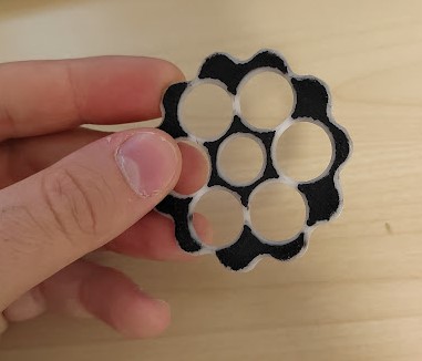
So I had an Idea. I printed a PLA raft and then, printed the cycloidal gear using POM. But POM as another problem. It shrink a lot when cooling. So I never manage to print the whole part because of warping.
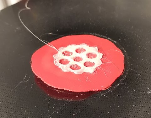
But I had another Idea, I thought about a multimaterial part using POM on the functionnal side of the part, and PETG for the inside and the structure. This way, I have good resistance, the part can be printed easily and I also have a good friction ratio on the outside.
Fortunately, I’m a PhD student working on multimaterial fabrication methods. So I printed it !
Harmonic drive
Another reducer which amaze me is the harmonic drive. This recucer use elestic deformation to bend a thin gear. Here is a little animation to expalined the principle :
I tried a lot of differents design and solution for this one. I design 5 different reducer to make it work. But this things is really challenging to build.
This was my first attempt using my SLA Printer.
The prototype worked for a few rotations but the inner gear finally broke. The deformation are too important resulting in high stress and fatigue in the part. I need to re-design those parts using smaller gears.
But the concept worked as you can see here below. I tried to 3D print a big harmonic reducer using my FDM printer. This work ! But I cannot create a smaller version of this. So I tried the actual cycloidal/planetary reducer.
Planetary gear
Similar principle than cycloidal disk, a planetary is oscilating in the reducer thank’s to an excentric shaft. Unlike classical planetary gearing, this one is a trade off between the cycloidal reducer and a planetary gearbox. I can be very compact, can handle big loads. But it doesn’t last long and is very noisy because of the vibration caused by an excentric shaft.

- Crank (K)
- Revolving input axis
- Rotating planetary gear (crank)
- Planetary gear (P)
- Fixed internal sun gear (S)
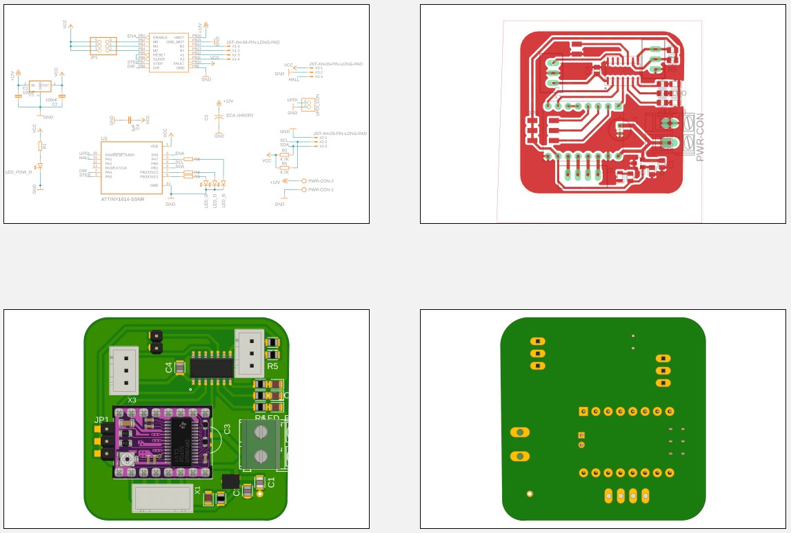
Electronics design
Here is the electronic design made using Fusion 360. Please check out week 7 if you’re interested in PCB design using fusion360 - Eagle.
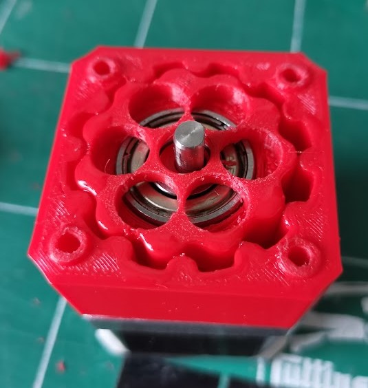
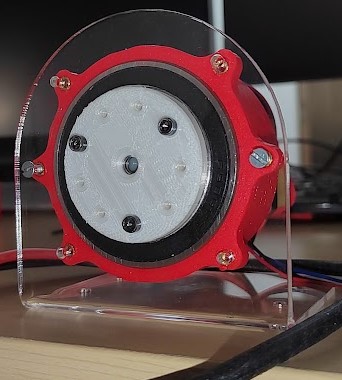
Final product gallery
Download
External links :
Embedded links
- Bearing
- Bended Motor holder
- Cycloidal reducer
- Flat bearing
- MotorBoard
- Needle Roller
- Nema 17
- Nema 23
- Reducer v1
- Reducer v2
- Reducer Final
- Electronic design