Fusion 360
I’ve been using Fusion 360 for a while now but after all these complicated way of 3D designing, comming back to a pretty interface is very pleasant ! Fusion 360 is a PDM solution. A Product design manager is a piece of software which provide a whole set of tools to manage your design process.
Fusion 360 is divided into different workspace :
- 3D design
- Realistic rendering
- Generative design
- Animation
- Multiphysics simulation
- 2D Drawing
Each workspace have a set of tools and usage. We will use the 3D design environment and the rendering workspace today.
Nema 23 CAD
Like what I have done in freeCAD, I started by creating a 2D Sketch on a plane.
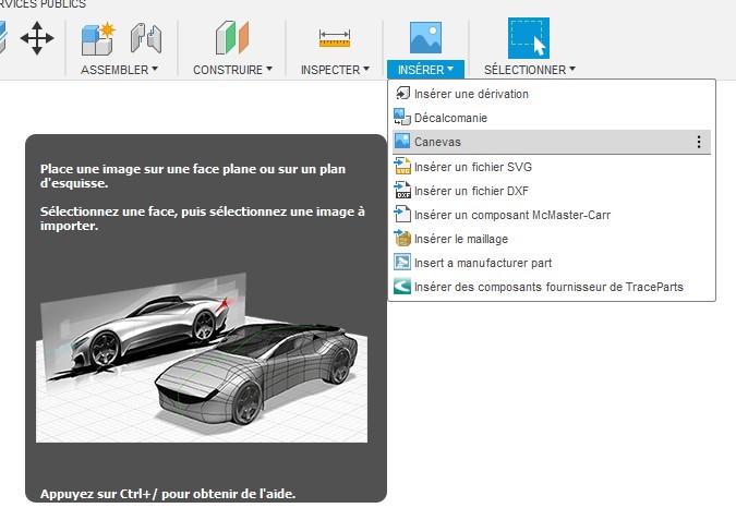
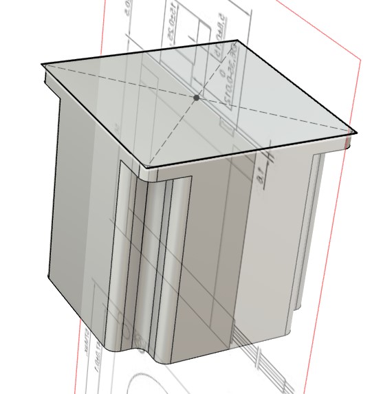
One thing I like a lot in fusion, is the ability to place a transparent canvas in the workspace. It is not very reliable in terms of position and dimension. But it can help to handle the missing value of the technical drawing. I used the official drawing of the Nema 23 in order to have a reference. Using both measure and the drawing I way manage to get a reliable Nema23 model.
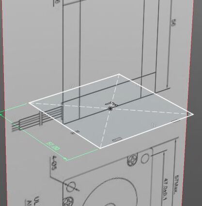
I began by creating a new sketch with a centered rectangle. I measure the width of the stepper motor body and apply this measure to the rectangle. Then I imported a picture into a transparent canvas to visualize want I’m doing along the cad process.
I placed the canvas carefully to make sure the position of the sketch match the bottom of the stepper.
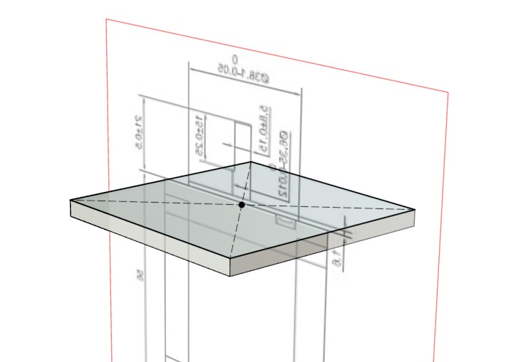
I started to give volume to the previous sketch to create the top plate of the stepper.
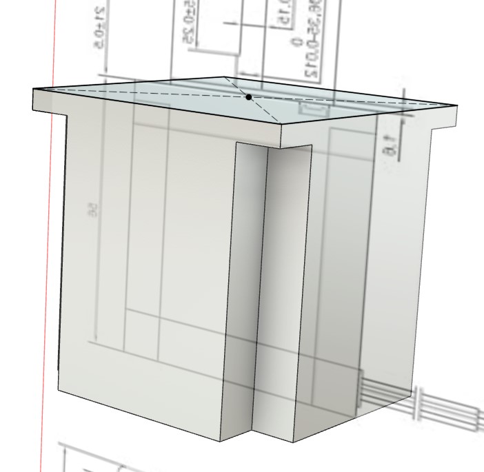
After another sketch, I finally extrude the rest of the motor. The overall shape of the stepper is appearing.
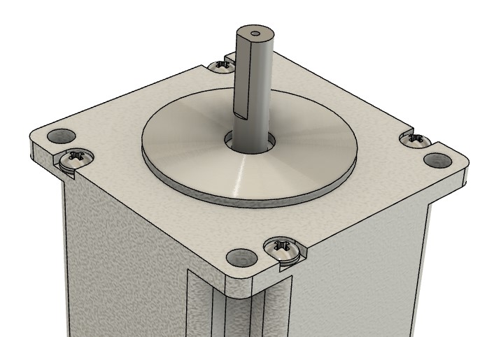
At this point, the motor look very sharp and not faithful to the real model. To smooth the sharp corner, I used Filet. Note that filet are difficult to measure precisely. Since it is just a digital model from a real product precision isn’t crucial for filet. We have to be precise when designing functional feature such as screw holes instead…
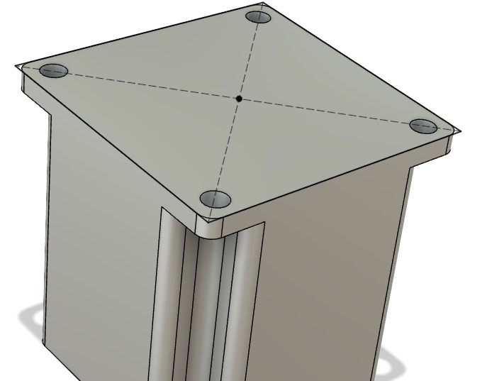
The Nema23 is fixed to any other part using 4 holes. I’ll use those holes to screw everything together at the end, so I need those holes to fit in my final design. The position of the hole relative to the shaft is therefor crucial.
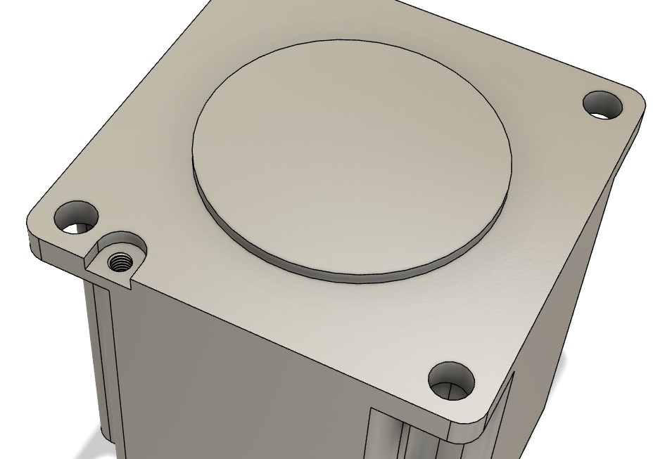
Although any detail are not useful in a digital model. I would like my model to be faithful to the real motor. The next feature is purely decorative. There are 4 screws fixing the keeping all the motor parts together. As the design is perfectly symetric around the center, I can use a pattern to model the screw once and repeat around the central axis.
First I design the screw and the hole for the screw head.
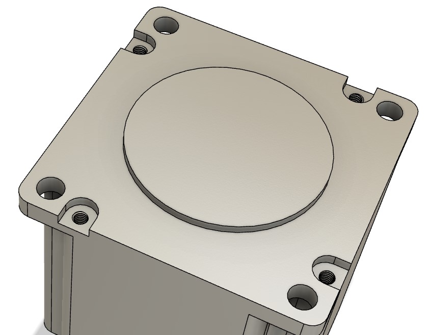
Then I repeated the pattern 4 times around the Z axis which is perfectly centered thanks to my first sketch
Drawing screw, nuts and stuff in Fusion can be frustrating. Fortunately, fusion embed several parts library. Those library contains thousands of parts reference such as screws bearing and so on. My favorite library is named McMaster-Carr. McMaster-Carr is a part supplier you can basically do shopping on their website but they also provide 3D model for most of their components. Fusion360 basically integrate the 3D model directly into your design. Just browse into McMaster-Carr and download the desired model.
That’s how I imported the following screws. There is a pretty good tutorial here if you’re interested.
You may have noticed that the texture on my design changed. That’s because I applied a material to the motor. In Fusion, if you press ++A++, you’ll eventually open up the appearance menu. This toolbox contains a bunch of material with unique texture and color sorted by category. I applied the cast aluminum material to the whole motor for now. But As you may guess, we need to divide our motor into multiple parts to set the right material to the stepper parts.
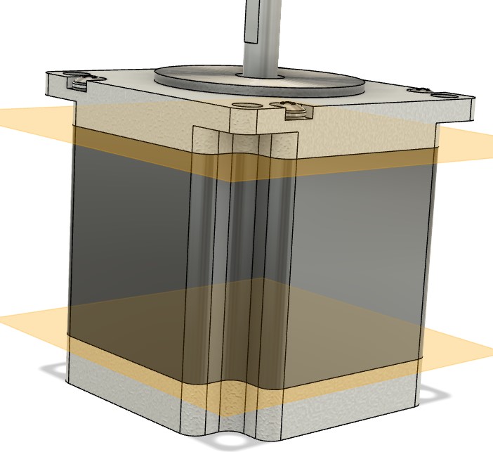
To create those parts, I create two construction plane using the transparent canvas. Note that my plane are parallel to the XY plane. Then I used the slip body function to divide the main body according the construction planes. This created 2 additionals body by intersecting the plane with the volume.
Then I simply used the appearance menu to set a black paint the middle body.
I added small colored wired to keep wiring in mind during the Assembly process.
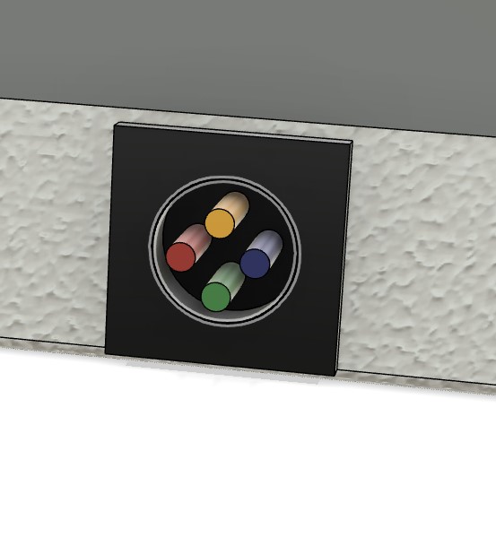
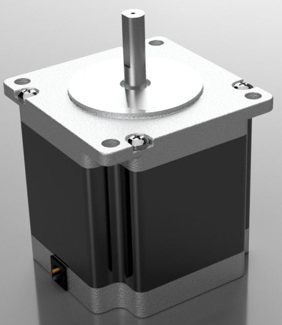
Here is how it looks :
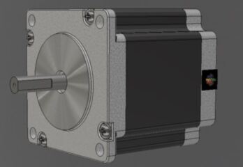
Using the renderer workspace I click the play button to run the render locally and after a few minutes. I got this result :
How do you think ?
Downloads
You can find all my 3D files here :
Final project CAD
After finishing the Nema23 stepper motor, I have spent a bit of time working on my first strain wave gearing design. My first design was inspired by the video from How to Mechatronics
This reducer is basically made of 3 main parts :
- The flexspline (Spining and bending gear)
- The circular spline (Static inner gear)
- The wave generator (Elliptic bearing)
I plan to the laser cutter for the wave generator, So I design a flat plate with hole to fix 608zz Ball bearings which are very common. Then I designed two circular gear using the fusion360 extension named spurGear available in the fusion appstore. This extension allows creating circular gear according to users parameters. I tested some random value for now to experiment on the design and assembly process.
I made this animation to show each step of design : Fusion 360 keeps track of everything you did in the timeline located at the bottom of the interface. When you click on play, it renders the whole design animation. Using Screen2Gif I recorded that sequence :
Note that I used ball bearings from McMaster-carr. This is only a virtual prototype. This version isn’t functional but I’will push the research further in the project seciton.
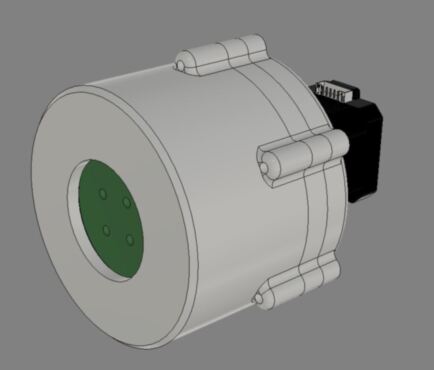
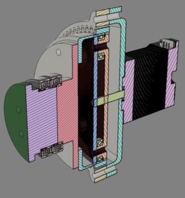
Here is the final prototype and its inner view ;
Fusion360 as also an animation workspace. To create an animation from a mechanical system, simply move the desired parts and save a frame with the current position of each part. By moving them using the actual joint, you let Fusion calculate the position of other part of the design. But I didn’t find a proper way to display the flex spline deformation wave … I need using a dynamic deformation simulation to do so…
Here is how my animation looks like.
To create this animation I simply made the wave generator rotate and hide other components to see the whole Idea. There is a pretty decent tutorial here if you’re interested in animation using Fusion360 This design as evolved since this assignment and I have lost the design original file. But the last version will be available soon in the project section.
Downloads
You can find all my 3D files here :