Embedded programming
For this week assignment we had to :
- Link to the group assignment page
- Documented what you learned reading a microcontroller datasheet
- Programmed your board
- Described the programming process you used
- Included your source code
- Included a short ‘hero video’ of your board
Group Assignment
For the group assignment I decided to compare two-way of programming microcontrollers. I will cover the programming workflow for :
- ATTiny 412 with Arduino
- Attiny 412 with PlatformIO
- ESP32 programming with Arduino
- ESP32 programming with PlatformIO
For all the board I will try to upload a simple blink program. We will discuss the performance and the process at the end.
ATTiny 412 - Arduino
Starting with the ATTiny 412. This chip is part of the tinyAVR 1-Series. As other member of the series, the Attiny412 can be programmed using only one data pin. This protocol named UPDI (Unified program debug interface) enables single pin programming.
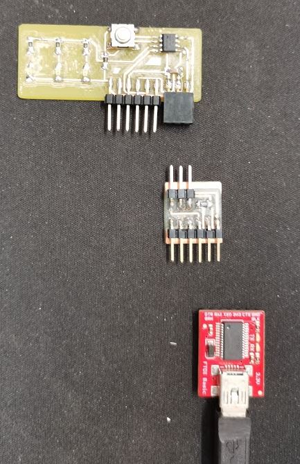
However, the board hasn’t any serial compatibility and need an external FTDI chip to communicate with the PC. Fortunately we have a FTDI programmer, and we made a FTDI -> UPDI adapter during week 5
To use attiny with Arduino, we will need to install a few add-on.
There is a really complete tutorial available online. As we’ve created a Blink board during week 5 we won’t create a breakout, but we will use the actual board instead.
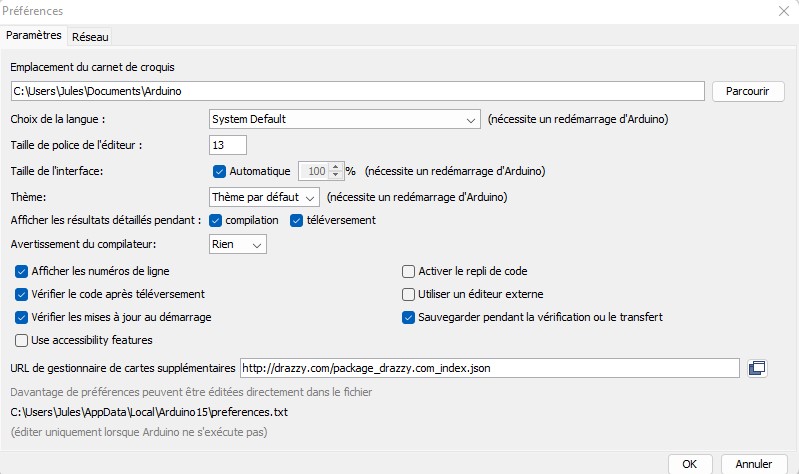
To add activate the features needed to program the attiny, we need to install an add-on by adding the line into the Additional board manager URL in Arduino settings.
http://drazzy.com/package_drazzy.com_index.json
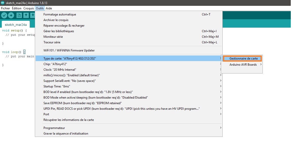
This will add new package available for download in the board manager. To install those additionnal package, Open up the board manager and look for the package named megatinycore, then install the latest version.
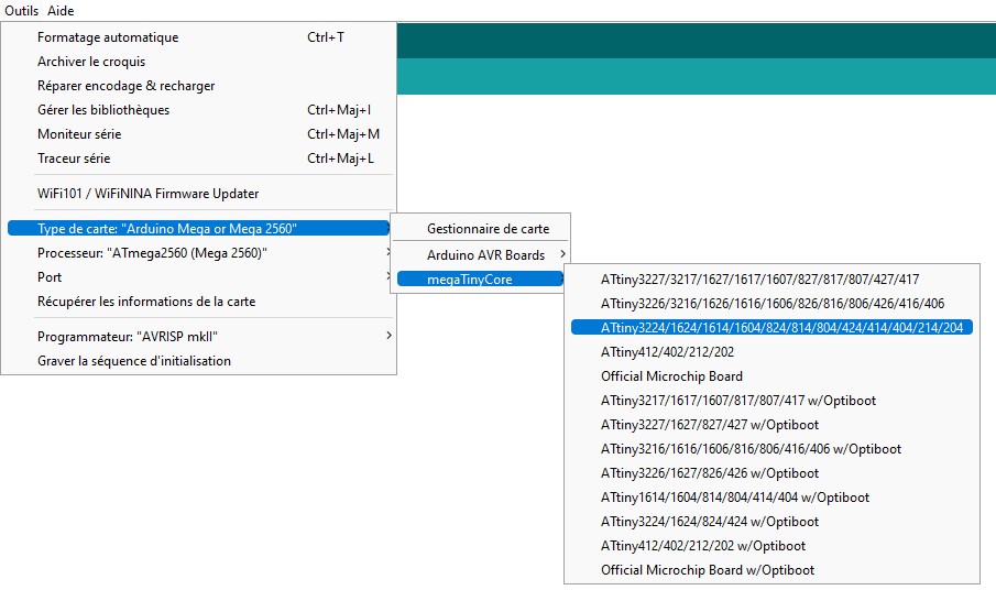
After a minute or two, the package should be installed. We now have to set up the programming environment. Our code will be compiled for the ATTiny 412 specifically. Thus, we will choose Attiny412 into the board settings.
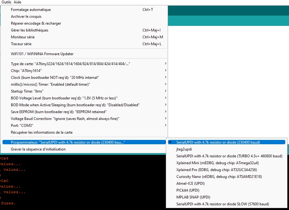
Then we need to specify how we program the board. We will be using the Serial UPDI protocol thank’s to the adpater. So in the Programmer settings let’s select this protocol.
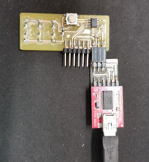
Then to program the board we have to plug the FTDI to the Serial port of the PC and the UPDI adpter in the FTDI module. Then we plug the UPDI to the board.
Note : The board need to be powered to be programmed. So the FTDI will also supply 5V to the chip.
Then all we have to do is clicking the upload button. Hopefully, the board should blink.
I used the blink program available in Arduino’s examples. I just changed the LED pin since there is no builtin LED on the chip.
// the setup function runs once when you press reset or power the board
void setup() {
  // initialize digital pin LED_BUILTIN as an output.
  pinMode(1, OUTPUT);
}

// the loop function runs over and over again forever
void loop() {
  digitalWrite(1, HIGH);   // turn the LED on (HIGH is the voltage level)
  delay(1000);                       // wait for a second
  digitalWrite(1, LOW);    // turn the LED off by making the voltage LOW
  delay(1000);                       // wait for a second
}
ATTiny 412 - PlatformIO
PlatformIO is an open-source project providing a complete platform for embedded programming. It can be installed as an addon of Visual studio code or Atom. Both are advanced text editor. If you’re on MacOS, you can choose one of them. On Windows, please use VS Code.
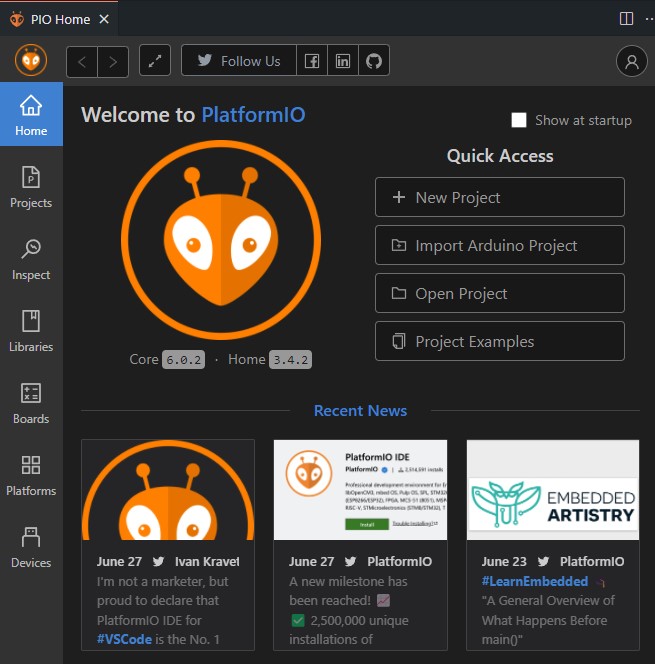
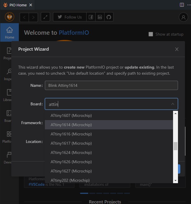
In VSCode, open the extension panel on the left, and search for platformIO. Then click install. The editor should restart. Then you can go to platformIO and click new project.
Then, PIO will prompt the project configuration pop up. We now have to select the board and the framework we will be using. There are plenty of frameworks available. Framework are like a library for a specific architecture.
Then PIO will generate the project files and folder. Here is the directory structure. As you can see, it contains a folder named src. This folder will contain our source code. Usually for small project, creating a main.cpp file into that folder is sufficient.
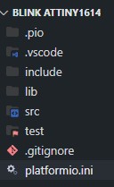
But you can really take advantage of this structure with bigger project just like this one :
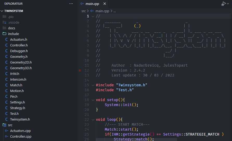
You maybe wonder what’s the platform.ini file. This is where the project config goes. You don’t have to use the config UI above actually. I’m usually setting everything manually. But it is good to have a basic project template.
Here is the config we should have now :
[env:ATtiny1614]
platform = atmelmegaavr
board = ATtiny1614
framework = arduino
If we try to upload a code now, PIO won’t be able to know how to do that. He will probably try to find a serial port available. But with the wrong protocol he won’t do a lot…
So we have to specify that our board is programmed using the UPDI protocol. For that purpose, here is the script I came up with :
[env:tiny1614]
platform = atmelmegaavr
framework = arduino
board = ATtiny1614
upload_speed = 115200
upload_port = COM3
upload_flags =
    -d
    tiny1614
    -c
    $UPLOAD_PORT
    -b
    $UPLOAD_SPEED
upload_command = pyupdi $UPLOAD_FLAGS -f $SOURCE
This great project can be installed using pip with the following command :
pip install https://github.com/mraardvark/pyupdi/archive/master.zip
Once you installed the upload tools, create a src/main.cpp and copy paste this code :
#include <Arduino.h> //Include the Arduino framework
// the setup function runs once when you press reset or power the board
void setup() {
  // initialize digital pin LED_BUILTIN as an output.
  pinMode(8, OUTPUT);
}

// the loop function runs over and over again forever
void loop() {
  digitalWrite(8, HIGH);   // turn the LED on (HIGH is the voltage level)
  delay(1000);                       // wait for a second
  digitalWrite(8, LOW);    // turn the LED off by making the voltage LOW
  delay(1000);                       // wait for a second
}
Warning
You may have seen that I added a line to the code we used before.
Actually we have to #include <Arduino.h> in our code now, otherwise it won’t compile.
The reason is that the Arduino IDE add this line to every file you compile with it. Here we are using pure C++. No lifebuoy anymore !
Things are becoming serious !
Personal assignment
This week we had to study a microcontroller datasheet… I read a bit the documentation about the ATTiny 412,
I’ve learned a few things about this chip. First, this microcontroller is 8 bits microcontroller from AVR. It can run up to 20MHz but can also run slower if you need low power consumption. Using ultra low power mode, you’ll be able to create stuff that can work for 10 years or more using a simple battery. Impressive ! The Ultra low power mode tells the chip to run at 32kHz
The chip as the following memory capacity :
- 4Kb of flash memory (For the program, constant …)
- 128b of EEPROM to save data from on run to another even with power off
- 256b of SRAM for dynamic data storage (variable, operation, buffer…)
The board can be programed using the single pin programming protocol UPDI.
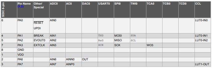
Talking about the tiny 412 pins, the chip has 8 pins. 5 of them can actually be used in your programs I used the chip pinout to remind the wiring of everything. It is possible to use external multiplexer if needed.
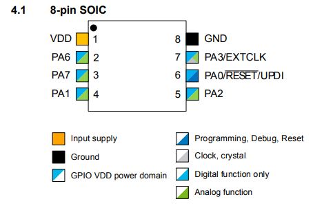
Here are the features available on each pin. For our LED test board, we will need an output for the LEDs and also an input for the button. We can also add a FTDI Serial interface. I created this board during week9.
On my last board I forgot to wire the button to the microcontroller.... I had to mill a new board fixing that.
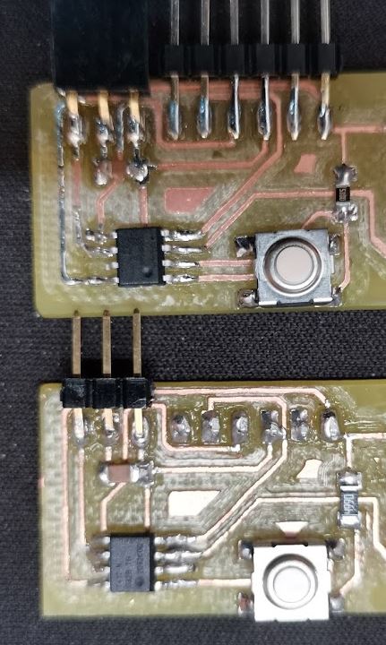
I had a lot of trouble programming my new board even if the first board was pretty easy to program… Indeed, I soldered a wrong microcontroller… Attiny85 instead of 412 (They mixed in my zip bag !).
The tiny85 doesn’t support UPDI programming… and the pin are not organized in the same way.
After changing to the right microcontroller, I soldered everything, programmed, and it blinked !
Here is the full workflow :
Attiny 85
I first used megaTinycore from SpaceConde on GitHub. I used his board package to program my board using Arduino IDE. To install megaTinycore please check the above tutorial
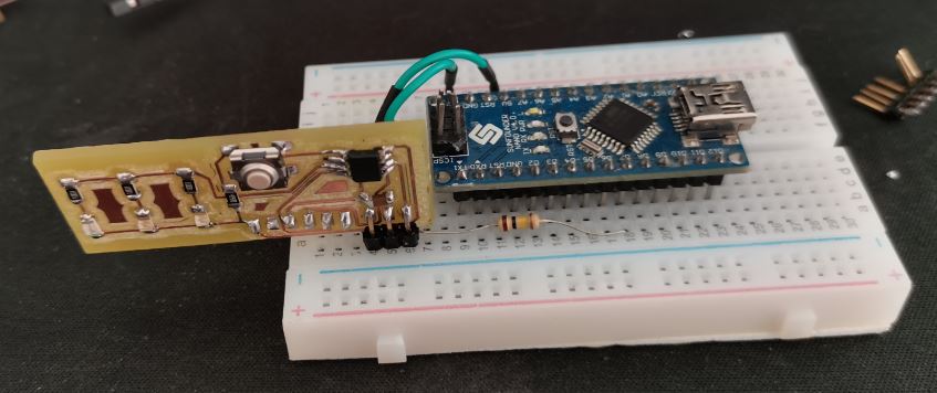
At that time I didn’t figure out why my board wasn’t working properly, I tried to program the ATtiny85 as an Attiny 412… As PyUpdi wasn’t working, I wired an Arduino nano to test the JTAG programming methods.
It didn’t work … As expected. So, I tried to figure out what was going on using a multimeter to check the continuity of my board.
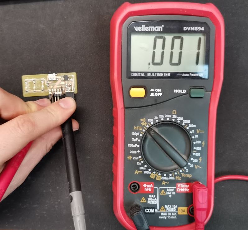
I figure out it was the microcontroller at 2am ! :D Finally I unsoldered the tiny85 and try again with the 412. It worked way better…
Attiny 412
I started all over again with a simple blink code. To test if the upload process was working.
// the setup function runs once when you press reset or power the board
void setup() {
  // initialize digital pin LED_BUILTIN as an output.
  pinMode(1, OUTPUT);
}

// the loop function runs over and over again forever
void loop() {
  digitalWrite(1, HIGH);   // turn the LED on (HIGH is the voltage level)
  delay(1000);                       // wait for a second
  digitalWrite(1, LOW);    // turn the LED off by making the voltage LOW
  delay(1000);                       // wait for a second
}
I selected the board in Arduino, change the programmer to UPDI 4k resistor. Plug everything together and upload the program.
After plugin everything together, I uploaded the program.
It blinked ! Back in business ! Then, we need to figure out how to turn on the LED when pressing the button. We need to link those pins somehow. We could just connect the wires on the board but let’s do that in the program.
The pinout from the datasheet wasn’t very clear on the pins I should use. But I found another pics online :
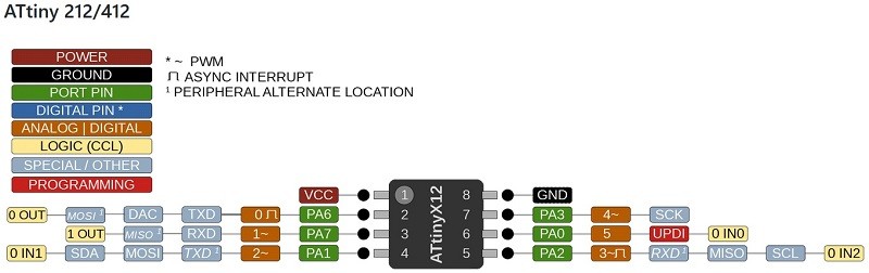
As you can see, our button is on pin 0 and the LED are on pin 1
// the setup function runs once when you press reset or power the board
void setup() {
  // initialize digital pin LED_BUILTIN as an output.
  pinMode(1, OUTPUT);
  pinMode(0, INPUT_PULLUP);
}

// the loop function runs over and over again forever
void loop() {
  digitalWrite(1, digitalRead(0));  // turn the LED on (HIGH is the voltage level)
  delay(200);                       // wait for a second
}
After flashing this code, the board doesn’t seem to work properly, When I was pressing the button, I discovered that he wasn’t properly soldered. I fixed that. Here is the result :
Downloads
- PlatformIO Blink tiny412 project
- PlatformIO Blink tiny1614 project
- Arduino Blink project
- Arduino Button Project