Networking and communication
For this week we had to :
- Linked to the group assignment page and reflected what you learned individually of the group assignment.
- Documented your project.
- Documented what you have learned from implementing networking and/or communication protocols.
- Explained the programming process/es you used.
- Outlined problems and how you fixed them.
- Included design files (or linked to where they are located if you are using a board you have designed and fabricated earlier) and original code.
Personal Assignment
For my final project I would like to be able to communicate with the board using the RC protocol. Radiocommand (RC) component usually use those kinds of protocols to avoid any compatibility issues between sensors, actuators or controller. For instance, Servomotor should receive on/off signal with a very precise timing. As most microcontroller can be very precise in time, you can transmit data using the time as a unit. PWM means Pulse Width modulation. This protocol is sending pulse at a precise frequency. Those pulses can vary in duration. This is how you send different value.
Here is an example with servomotor :

The servo are controlled using this principle, where each pulse width is associated with an angular position. This is an efficient way to control something precisely without sending lots of data using a communication protocol. Instead, the trick is to use the ability of microcontroller to measure time precisely to transmit data using time has unit.
Using this methods ensure a total compatibility of my project with any microcontroller since modern UC are able to be fast enough to handle 50Hz time based data exchange.
Wiring
There is an excellent guide on the Arduino website speaking about the I2C protocol. If interested in, please check out the button below.
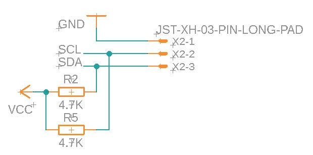
My board has an I2C input already. See [week 9] to know how I make the board. Here is the actual board schematic :
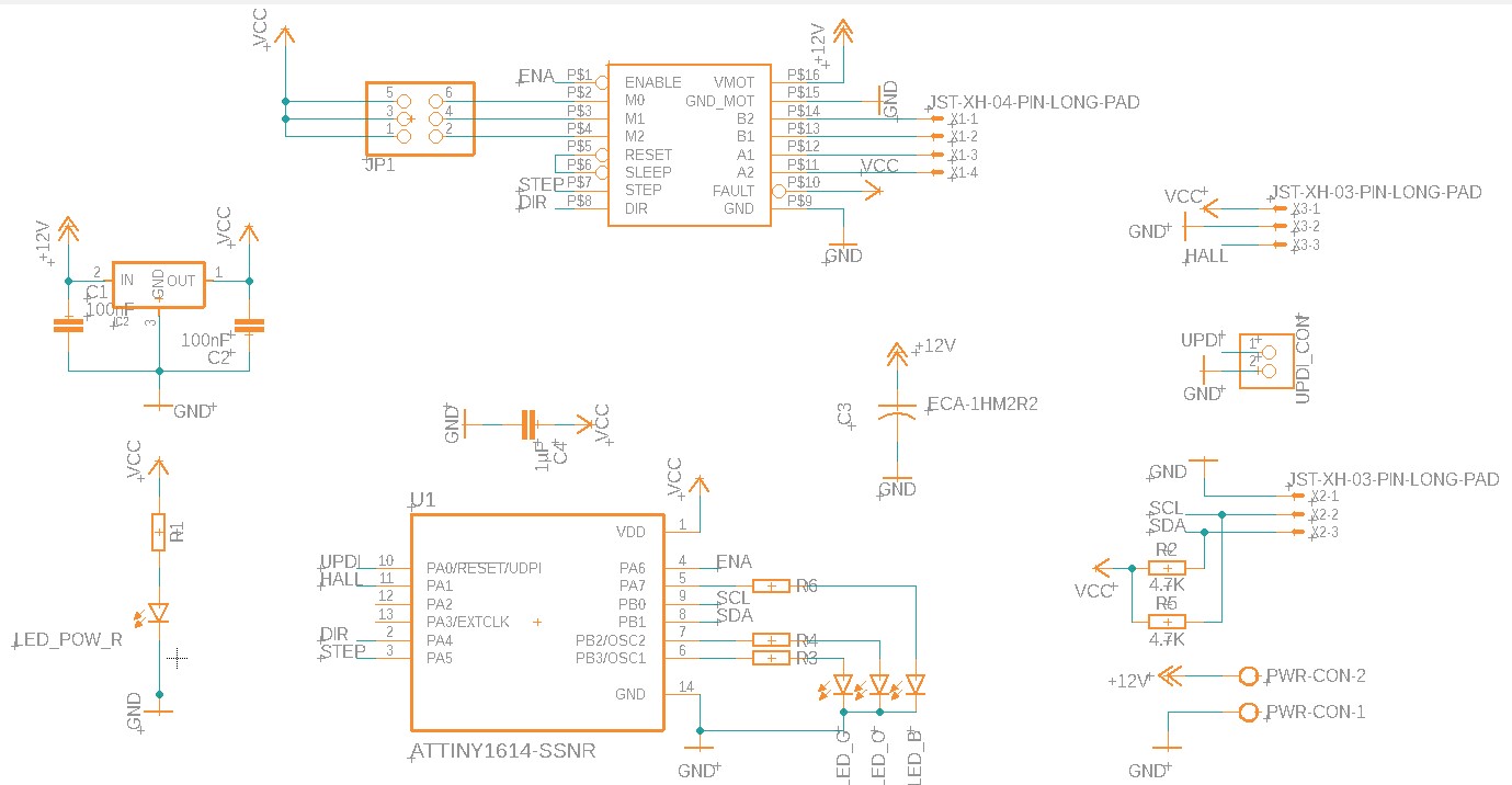
As you can see the SDA and SCL pins are linked to the I2C connector. I also used two 4.7k Ohm resistor as pull-up resistors.
Originally the I2C protocol is made to connect up to 254 peripherals together using only two wires. However,there is always one master microcontroller connected managing the others. For instance if we have three Arduino connected together using I2C protocol, the master microcontroller can ask data to all other microcontrollers connected. But the opposite is impossible.
If A is the master, B cannot ask something to C. Instead you may do it like this:
- A: Hey B ! Is there anything you need from C ?
- B: Hey A! I need the value of the sensor C !
- A: OK B
- A: C, may you send your sensor value ?
- C: Hey A, here is the value : 0.0220452
- A: Thank you C ! I received 0.0220452 Is it OK ?
- C: Yep !
- A: Hey B, here is the value : 0.0220452
- B: _Hey A ! I received 0.0220452 Is it OK ?
- A: Yep !
- …
However, multimaster protocol also exist with I2C.
Each time a message is sent, the master sends the address of the microcontroller he wants to speak to. Then every node of the network compare this adress to their own. If it’s match, It may eventually answer to the command.
Programming RC protocol
For my final project, I would like to use to communication mode. RC Servo protocol and I2C. Let’s start with servo communication.
As I said before, Servo communication is time based. So we need to keep track of an input and record when the state of the pin change. There is only 0 or 1. The input is digital even if you will receive data at the end.
I created a new file named servoControl.h.
First, We need to initialize the input pin somehow. I will register it as an input :
#pragma once

#include "pin.h"
#include <Arduino.h>


namespace ServoControl{
    void init(){
        pinMode(Pin::SERVO, INPUT);
    }
}
Then we need to imagine a protocol get the data. Let’s get the data pin state.
#pragma once

#include "pin.h"
#include <Arduino.h>


namespace ServoControl{

    bool lastState  = false; //Last pin state

    void init(){
        pinMode(Pin::SERVO, INPUT); //Register an input
    }

    void check(){
        bool state = digitalReadFast(Pin::SERVO); //Read the state of the Servo pin
        //Note : I'm using digitalReadFast to save a bit of time...

        if(state != lastState){         //Check if the state is has changed
            lastState = state;          // If it did, store the new state
        }
    }
}
Now we need to keep track of the time. I’ll use the micros() function to calculate the time since the last pulse.
#pragma once

#include "pin.h"
#include <Arduino.h>


namespace ServoControl{

    bool lastState  = false; //Last pin state
    unsigned long tlastUp    = 0; //Last time pin was up
    unsigned long tlastDown  = 0; //Last time pin was down

    void init(){
        pinMode(Pin::SERVO, INPUT); //Register an input
    }

    void check(){
        bool state = digitalReadFast(Pin::SERVO); //Read the state of the Servo pin
        //Note : I'm using digitalReadFast to save a bit of time...

        if(state != lastState){         //Check if the state is has changed
            lastState = state;          // If it did, store the new state

            if(state){
                tlastUp = micros();   //Montant

            }else{
                tlastDown = micros(); //Descendant

            }
        }
    }
}
Now we can calculate pulse width which is equal to the difference between tlastUp and tlastDown.
#pragma once

#include "pin.h"
#include <Arduino.h>


namespace ServoControl{

    bool lastState  = false; //Last pin state
    unsigned long tlastUp    = 0; //Last time pin was up
    unsigned long tlastDown  = 0; //Last time pin was down
    unsigned long pulseWidth = 0;

    void init(){
        pinMode(Pin::SERVO, INPUT); //Register an input
    }

    void check(){
        bool state = digitalReadFast(Pin::SERVO); //Read the state of the Servo pin
        //Note : I'm using digitalReadFast to save a bit of time...

        if(state != lastState){         //Check if the state is has changed
            lastState = state;          // If it did, store the new state

            if(state){
                tlastUp = micros();   //Montant
            }else{
                tlastDown = micros(); //Descendant

                pulseWidth = tlastDown - tlastUp; //Calculate the pulse width
                int target = ((float(pulseWidth) - 1500.0f)/1500.0f) * Stepper::range; // convert the pulseWidth to angle
                Stepper::setTarget(target); //Send the command to the Stepper

            }
        }
    }
}
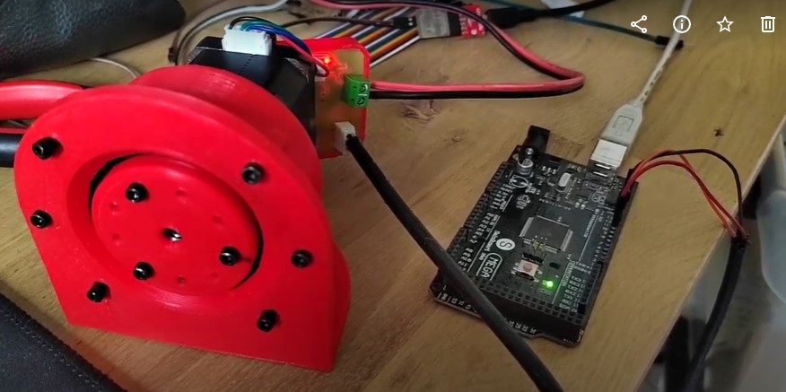
I uploaded this code to my final project board using PlatformIO and the UPDI protocol. See week 9 for more information about that. Then I connected my SmartMotor input to a digital output of an Arduino Mega 2560.
Now, I should be able to use the standard Arduino library to control my final project. Let’s try a simple code to check that out :
#include <Servo.h>

Servo myservo;

void setup() {
  myservo.attach(6);
}

void loop() {
  myservo.write(0);
  delay(4000);
  myservo.write(90);
  delay(4000);
}
I uploaded this code into the Arduino mega using Arduino IDE. Since last time I’ve built my reducer. So here is the video of how he moves with this code.
As you can see it works ! But there is still a problem, the signal isn’t perfect, and the motor goes wobbly when he reach a position. Whe need to filter this electrical noise somehow. All the pulses should be 20ms spaced. So if a pulse last longer that than, it is probably a wrong pulse. Let’s implements that to see if it works.
#pragma once

#include "pin.h"
#include "stepper.h"
#include <Arduino.h>

namespace ServoControl{
    unsigned long tlastUp    = 0;
    unsigned long tlastDown  = 0;
    bool lastState  = false;
    unsigned long pulseWidth = 0;
    unsigned long lastpulseWidth = 0;

    void init(){
        pinMode(Pin::SERVO, INPUT);
    }
    void check(){
        bool state = digitalReadFast(Pin::SERVO);
        if(state != lastState){
            lastState = state;
            if(state){
                tlastUp = micros();   //Montant
                Led::ledB(true);
            }else{
                tlastDown = micros(); //Descendant
                pulseWidth = tlastDown - tlastUp;

                if(pulseWidth > 200 && abs(lastpulseWidth - pulseWidth) > 20){
                    lastpulseWidth = pulseWidth;
                    int target = ((float(pulseWidth) - 1500.0f)/1500.0f) * Stepper::range;
                    Stepper::setTarget(target);
                    Led::ledB(false);
                }
            }
        }
    }

    bool isEnabled(){
        return true;
    }
} // namespace ServoControl
I also added a little debug LED to know when the Arduino is sending data. It’s funny because the LED intensity change with the signal. It is definitely a cool debug feature ! I uploaded the new code into my board and let the Arduino mega with the simple sweep code.
Here is how it performs now :
Programming I2C communication
Let’s implements I2C communication now. I want to be able to communicate with the Arduino using the serial port. Then, the Arduino will send command to my motor controller using the I2C protocol.
First, we need to read the serial port on the Arduinouino. Let’s create a very simple command interpreter :
void setup() {
  Serial.begin(9600);  // start serial for output
  delay(1000);
}

void loop() {
  while(Serial.available()){
    byte buf = Serial.read(); //Store the received serial data
    dataBuf += (char)buf;     //add those data to the buffer

    if (buf == '\n') {  // Command recevied and ready.
      dataBuf.trim();   //remove the last character

      if(dataBuf.charAt(0) == 'm' || dataBuf.charAt(0) == 'M'){ //if the command is a move command
        String valStr = dataBuf.substring(1); //remove useless characters
        int val = valStr.toInt();   //convert the received data to an int
        Serial.print("[I2C] <- : Sending Move to "); //print the received int

      }else{
          Serial.print("Unknown command"); //print the received int
      }

      dataBuf = ""; // Clear the string ready for the next command.
    }
  }

  delay(800);
}
This code read an input from the serial and convert it to an int. For instance here is a basic exchange with the Arduino :
< M 100
> [I2C] <- : Sending Move to 100
< M 850
> [I2C] <- : Sending Move to 850
< Hello World
> Unknown command
Then we need to create a function to send data through I2C.
I created a i2c.cpp file in the smart stepper project from week 13
Inside that file, I created a new class named Intercom.
Here is the code I came up with :
i2C.cpp :
namespace Intercom{

    void init(){
        Wire.begin(ADRESS);
        Wire.onReceive(receiveEvent);
        Wire.onRequest(requestEvent);
    }

    void requestEvent(){

    }

    void receiveEvent(int howMany){
        if(howMany == 3){
            char command = Wire.read();

            if(command == 'm' || command == 'M'){
                byte b1 = Wire.read();
                byte b2 = Wire.read();

                int target = ((b1 & 0xFF) << 8) | (b2 & 0xFF);
                Stepper::setTarget(target);
            }
        }
    }
} // namespace Intercom
i2C.h :
#include <Wire.h>
#include "led.h"

//Adresse I2C du module de navigation
#define ADRESS 0x3C

namespace Intercom{

    void init();

    void requestEvent();
    void receiveEvent(int);

} // namespace Intercom
Then we need to modify the Arduino code to send the actual values. We need to convert an int to two bytes on this side. (As We are converting it back in the code above.)
I created this small function in the Arduino code :
void sendMove(int steps){
  Wire.beginTransmission(0x08); // transmit to device #8
  Wire.write('m');
  Wire.write(steps >> 8);      // sends one byte
  Wire.write(steps & 255); // sends two byte for an int
  Wire.endTransmission();       // stop transmitting
}
Then I modified the main function to send the values.
void setup() {
  Serial.begin(9600);  // start serial for output
  delay(1000);
}

void loop() {
  while(Serial.available()){
    byte buf = Serial.read(); //Store the received serial data
    dataBuf += (char)buf;     //add those data to the buffer

    if (buf == '\n') {  // Command recevied and ready.
      dataBuf.trim();   //remove the last character

      if(dataBuf.charAt(0) == 'm' || dataBuf.charAt(0) == 'M'){ //if the command is a move command
        String valStr = dataBuf.substring(1); //remove useless characters
        int val = valStr.toInt();   //convert the received data to an int
        Serial.print("[I2C] <- : Sending Move to "); //print the received int
        sendMove(val);

      }else{
          Serial.print("Unknown command"); //print the received int
      }

      dataBuf = ""; // Clear the string ready for the next command.
    }
  }

  delay(800);
}
Group assignments
This week we had to make two project communicate… I was alone in the lab, so I communicate between different version of my final project board. Basically what I need to do is on microcontroller to control the other’s peripherals. My board can handle 2 types of communication, I2C protocol and time based PWM signals.
My attempt for the group assignment is to use an Arduino mega, connected using the servo protocol to on of my board, which will send command trough I2C to another of my board.
Arduino -> (Servo protocol) -> Custom board v2 -> (I2C Protocol) -> Custom board v5
I modified my previous code to change a bit how it works. Board V5 has to be controlled using I2C protocol. So this code doesn’t change a lot. I just disable the ServoControl in the main.cpp file :
#include "pin.h"
#include "led.h"
#include "stepper.h"
#include "i2c.h"
#include "servoControl.h"

void setup() {
  Stepper::init();
  Led::init();
  Intercom::init();
  //ServoControl::init();
}

void loop() {
  Led::blink();

  //ServoControl::check();
  Stepper::update();
}
I also changed the ADRESS variable to 0x3C. This will be the slave adress. Then I ducplicate the code to create the master code for the V2 board.
I disabled the Stepper parts sinc this board will not be wired to the stepper. Then I modified the I2C class to make it act like a master board.
#include "i2c.h"

namespace Intercom{
    void init(){
        Wire.pins(6, 7);
        Wire.begin();
    }

    void sendMoveRequest(int angle){

        byte b1 = (byte) angle;
        byte b2 = (byte) (angle >> 8);

        Wire.beginTransmission(SLAVE);
        Wire.write('m');
        Wire.write(b1);
        Wire.write(b2);
        Wire.endTransmission();
    };

} // namespace Intercom
Here I’m sending an int over two bite using a bitshift operation. Then I send a command (“m”) folowed by the two bytes.
On the master board, those two bytes will be interpreted like that :
    void receiveEvent(int howMany){
        Led::ledB(true);
        if(howMany == 3){
            char command = Wire.read();

            if(command == 'm' || command == 'M'){
                byte b1 = Wire.read();
                byte b2 = Wire.read();

                int target = ((b1 & 255) << 8) | (b2 & 255);
                Stepper::setTarget(target);
                Led::ledB(true);
            }
        }
        Led::ledB(false);
    }
The two bytes are casted back into an Int. Be before, I’m checking if the command is a move commanc “m”. And if the packet size is equal to three.
Here is how it operates :
Downloads
Group assignement :
Individual assignment :