Quentino
Introduction
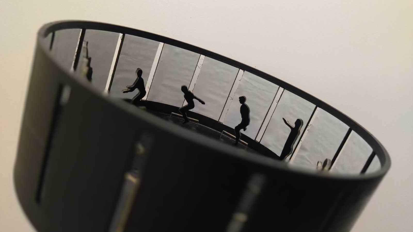
My final project is an interactive zoetrope designed to be a fun and educational tool for children. The main idea is that, besides enjoying watching the animated figures come to life as the device rotates, children can learn something valuable. Each character used in the zoetrope will be accompanied by a story that they can read, focused on teaching soft skills such as empathy, communication or teamwork, helping to strengthen their personal growth.
The zoetrope's operation is simple but very ingenious: I designed a board with an ATtiny 1614 microcontroller that controls an infrared sensor and a motor. When a child places his or her hand near the sensor, the motor is activated and turns the zoetrope. At the same time, LED lights turn on, making the experience more magical and eye-catching.
To build it, I am using digital fabrication tools such as laser cutting and 3D printing. The main materials are MDF for the internal structure, which is sturdy and easy to work with, and TPU filament for the outer shell, which has a soft, child-safe texture. Everything is designed with functionality, safety and making the device visually appealing in mind.
This project not only seeks to be educational and interactive, but also to contribute to the emotional and social development of children through the stories of the characters. My goal is to connect technology, learning and imagination in a practical and fun way, leaving a positive imprint on their growth.
System Diagram
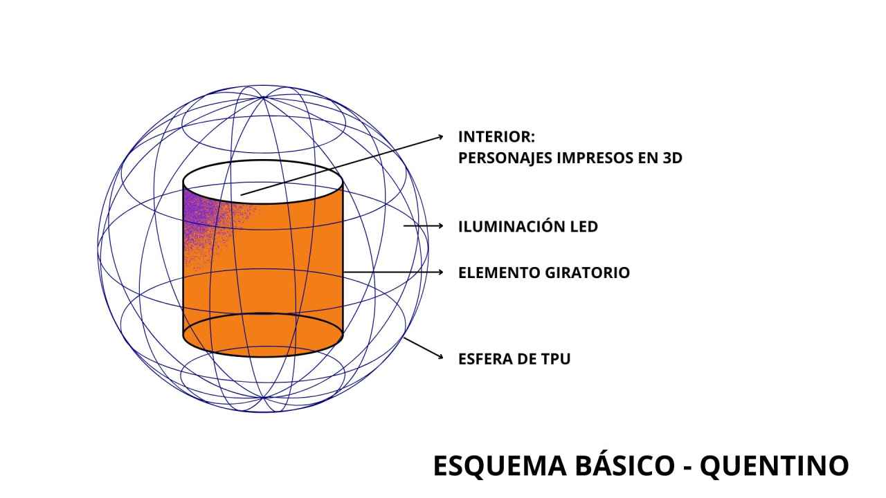
El zootropo funciona mediante la interacción de sus principales componentes electrónicos y estructurales:
Main components:
- ATtiny 1614 microcontroller: Acts as the brain of the system.
- Infrared sensor: Detects the presence of an object (such as a hand).
- Motor: Rotates the zoetrope when the sensor activates the signal.
- LEDs: Light up when an object is detected, providing an attractive visual element.
- Power supply: Provides power to all components.
Operation flow:
The infrared sensor detects a nearby object and sends a signal to the microcontroller.
The microcontroller simultaneously activates the motor and the LEDs.
The motor rotates the zoetrope, while the animated figures generate a visual effect that appears to give them movement.
The LEDs illuminate the device, enhancing the interactive experience.
Materials used:
- Internal structure: MDF, laser cut.
- Outer shell: TPU filament, 3D printed.
- Additional elements: LEDs, animated figures and connectors.
Task List
Introduction
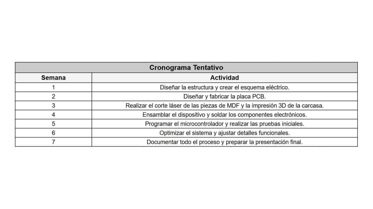
To complete the project, I will follow these organized phases:
Phase 1: Design and planning.
Design the structure of the zoetrope, integrating the materials (MDF and TPU) into a functional model.
Define the location of the LEDs and infrared sensor to maximize aesthetics and functionality.
Create the electrical schematic to integrate all the electronic components.
Design the PCB board with the ATtiny 1614 microcontroller and verify the necessary connections.
Phase 2: Fabrication and assembly
Laser cutting: Fabricate the MDF parts for the internal structure.
3D printing: Create the external housing using TPU, ensuring a perfect fit for the sensor, LEDs and motor.
Solder the electronic components onto the PCB and assemble the entire system into its structure.
Phase 3: Programming and testing
Program the microcontroller to:
Detect the infrared sensor signal.
Control the motor and LEDs in sync.
Test the entire system to ensure that the interactions between sensor, motor and LEDs work smoothly.
Adjust software and hardware as necessary.
Phase 4: Optimization and documentation
Adjust aesthetic and functional details, such as LED intensity or motor speed.
Document the entire process, including images, diagrams and videos of the device in action.
Prepare a clear and attractive final presentation to showcase the project.
The last assignment
Project presentation
This section will finally describe the process I finally followed for the presentation of my final project! After so much effort and many interrupted trips, I invite you to get to know my work. Let's go! 😃
Assignment
Final ProjectQuestions
What does it do?
The interactive device is an educational and playful tool for children. This hemispherical-shaped project allows children to explore the concept of animation through an integrated zoetrope. It also encourages curiosity and learning through direct manipulation and the use of interactive technology, such as an infrared sensor that activates the movement of the internal zoetrope.💪
Who's done what beforehand?
Zootropes have been known for a long time, however, in fab academy, there are few projects that have chosen this toy to develop their own version. I found some pages of students from previous years but not all of them managed to finish, the case that I found interesting and that is 100% developed was the following one:
Fab Academy 2017 - Juliana Henno Zoetrope 3D
The project “Sisyphus - The Interactive Rock” is an interactive installation that takes as inspiration the myth of Sisyphus. It is a rock that, when touched, begins to move as if it were in a constant effort, thanks to a system of motors and sensors controlled by a microcontroller. It is made with lightweight materials and a design that mimics the natural appearance of a rock. The idea behind the project is to make people reflect, in a fun and visual way, on the constant effort and persistence in life.💪
What did you design?
Structure: An interactive hemisphere, designed to be ergonomic and suitable for children to manipulate.
Internal mechanism: A motorized zoetrope controlled by an infrared sensor that will detect the proximity of children's hands to activate it.
Outer cover: A TPU (thermoplastic polyurethane) surface to make it soft and safe to the touch.
What materials and components were used?
Internal structure: MDF (medium density fiberboard).
Outer cover: TPU to ensure softness and durability.
Electronic components:
- Infrared sensor for motion detection.
- Stepper motor for zoetrope movement.
- Microcontroller (Arduino or ESP32) for system control.
Power source: Rechargeable battery.
Others: Cables, connectors, adhesives and safety finishes.
Where did they come from?
All these products are easy to find, here in Lima I found them in the center of the city, where they sell all kinds of accessories. In the case of TPU and MDF I will count on the material that is in our home as well as the machines that are operational.
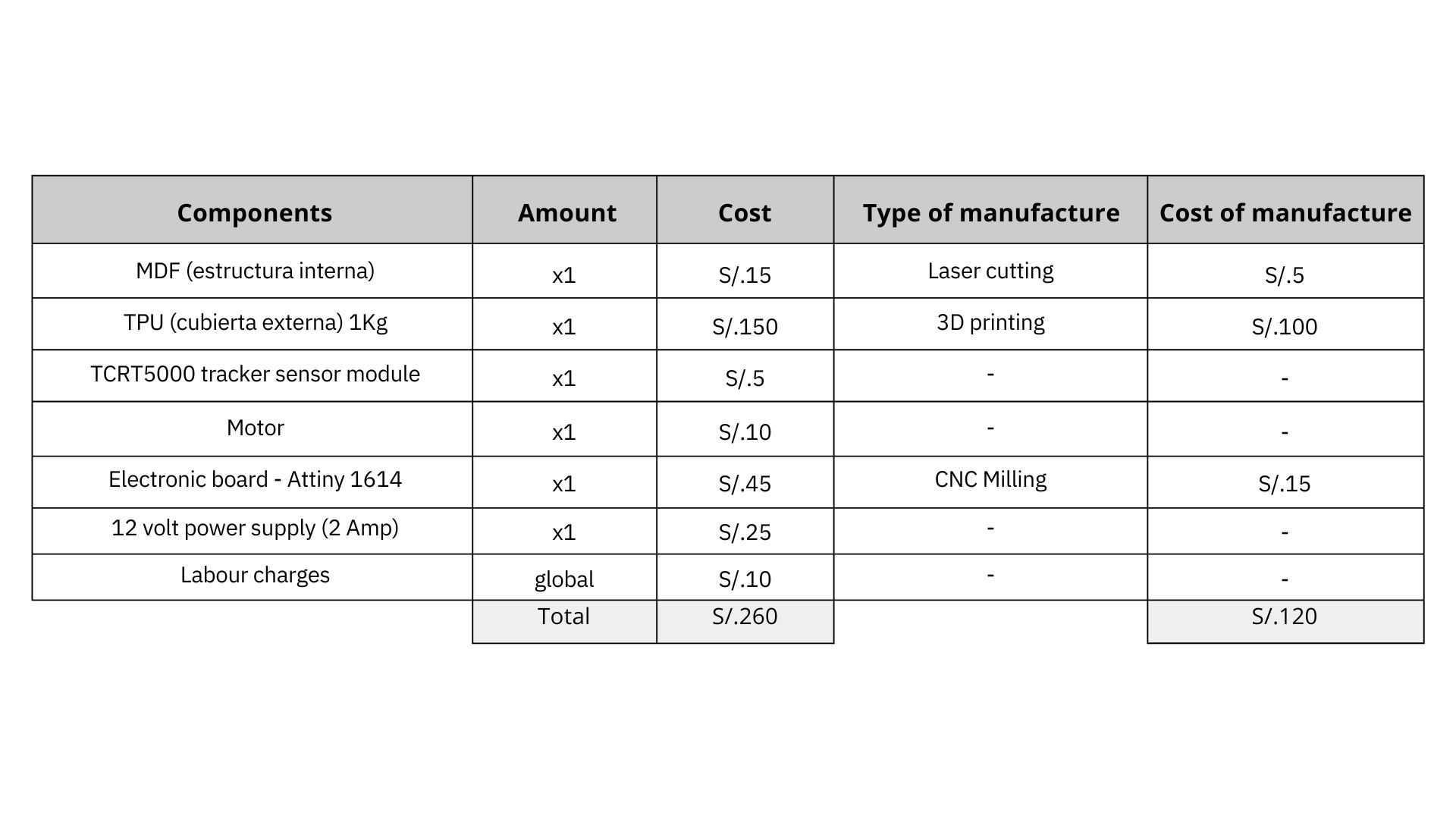
How much did they cost?
What parts and systems were made?
Internally: Hemispherical structure and zootrope supports in MDF, using laser cutting.
Externally: TPU shell molded or thermoformed to ensure a tight and secure fit.
Zoetrope: Manufactured with printed images and laser-cut supports.
What tools and processes were used?
- 2D and 3D design: Modeling of the hemisphere, the internal structure, and the parts of the zootrope.
- Subtractive manufacturing: Laser cutting for the MDF.
- Additive manufacturing or thermoforming: Creation of the TPU outer shell.
- Electronic production: Assembly and programming of sensors, motor and microcontroller.
- Integration and assembly: Final assembly of all parts.
All this I have already worked on in the following weeks:
- Computer aided desing
- Computer controlled cutting
- 3D printing
- Electronics design
- Electronics production
- Embedded programming
- Computer controlled machining
- Output devices
- Input devices
What questions were answered?
- How to ensure that the TPU adheres properly to the MDF?
- What is the optimal sensitivity of the infrared sensor for children?
- What rotation speed is suitable for clear zoetrope images?
- How to ensure the safety of children during use?
What worked? What didn't?
What works so far is the physical structure of the zootrope, with the installation of the basic components such as the motor and infrared sensor separately.
How was it evaluated?
Interactivity: The sensor must accurately detect proximity and activate the zoetrope.
Safety: The device must be smooth, without sharp edges, and made of non-toxic materials.
Durability: Withstand continuous use by children.
Visual effect: The zoetrope should generate a clear and attractive animation.
What are the implications?
1.Educational implications
Quentino encourages interactive, hands-on learning, allowing children to understand complex concepts such as animation in an accessible way.
It promotes the development of skills such as curiosity, manipulation and logical reasoning.
It contributes to pedagogical innovation by incorporating interactive technology into learning.
2.Technological implications
Introduces children to the use of technologies such as infrared sensors and motorized mechanisms, generating interest in technology from an early age.
Demonstrates how ergonomic and safe solutions, such as the use of TPU, can be integrated into educational devices.
3. Social implications
Could have a positive impact on educational communities by providing an accessible tool to encourage active learning.
Opens possibilities for collaboration between designers, educators and technology experts.
4. Design implications
Sets an example of how to integrate playful and functional design in a single device.
Reflects the importance of user-centered design, prioritizing safety and ergonomics.
Documentation
Final Projectprocess
Concept & Prototype
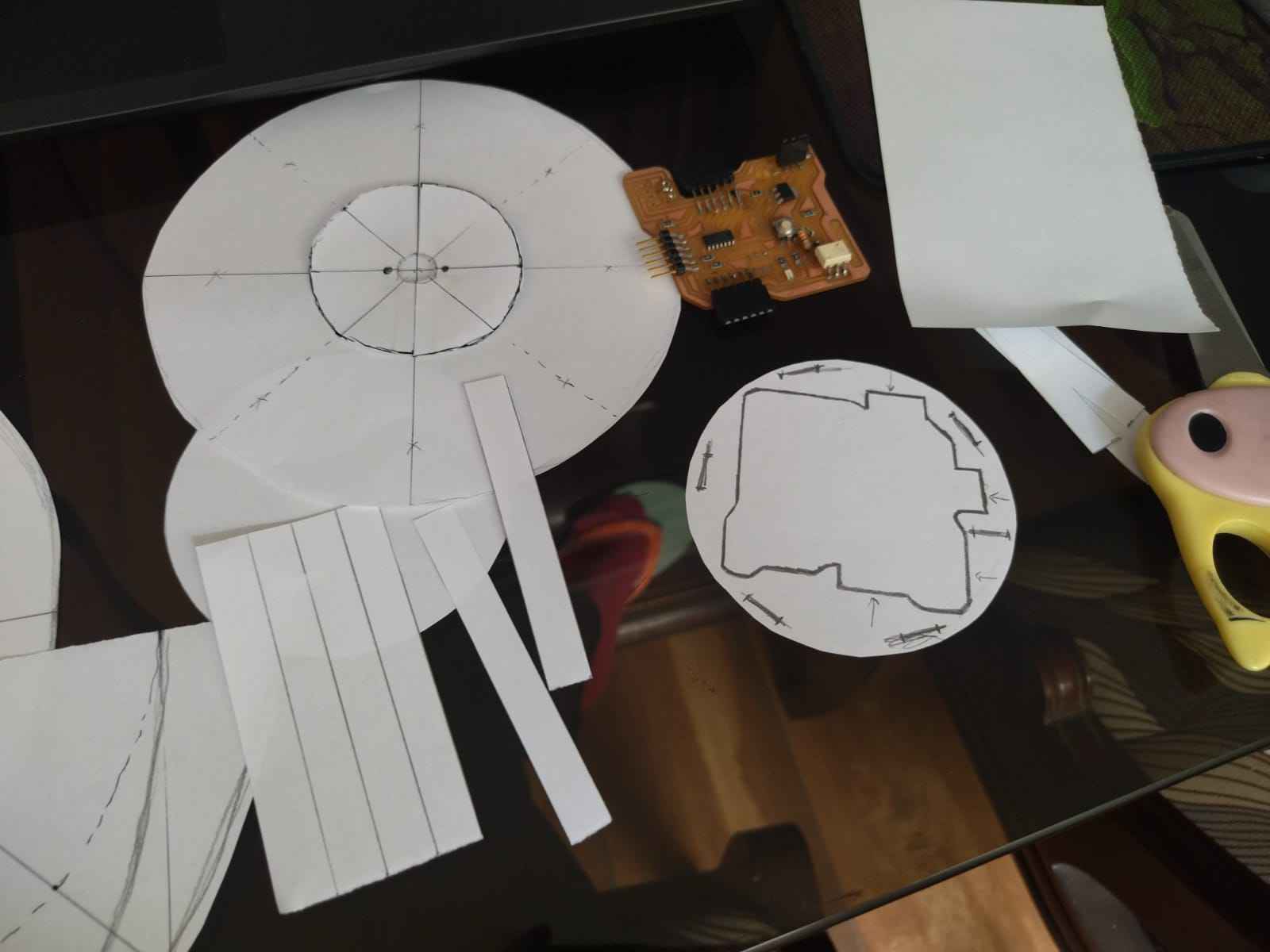
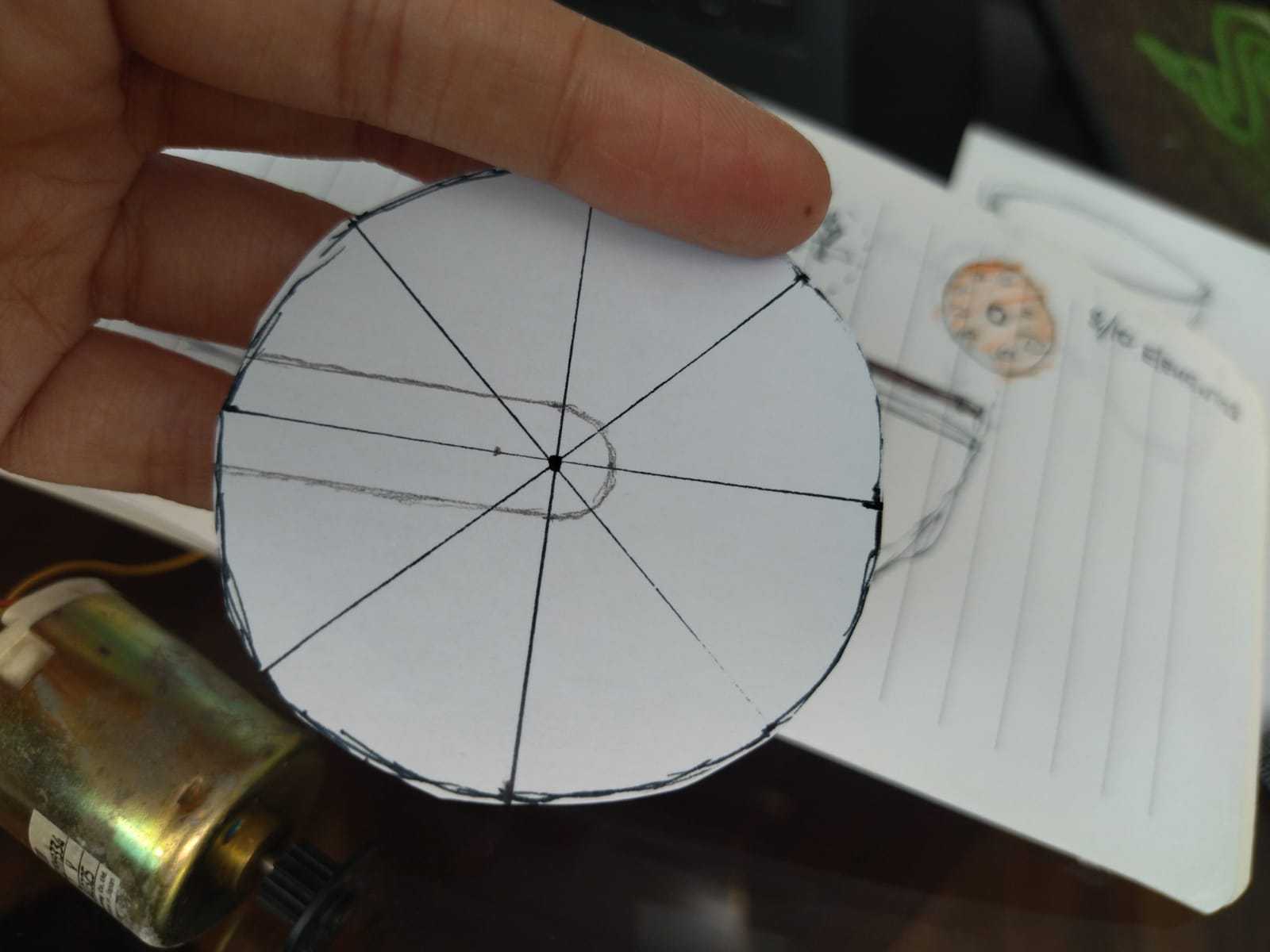
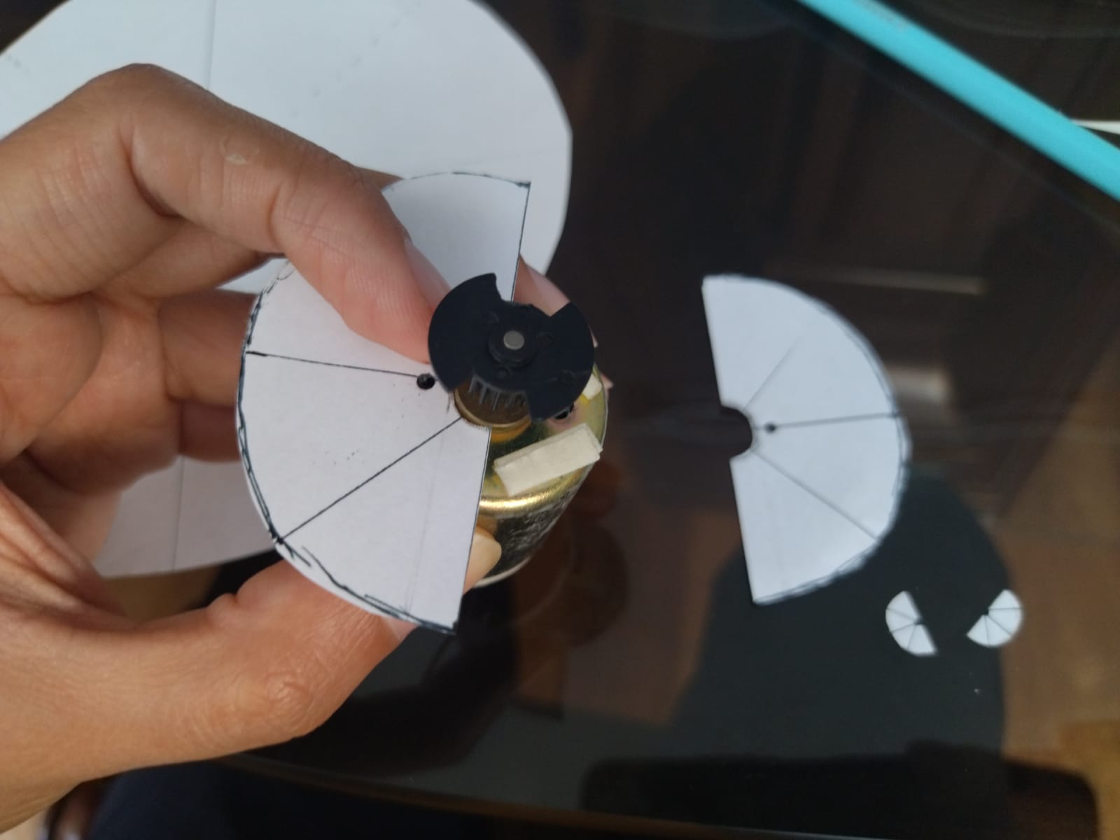
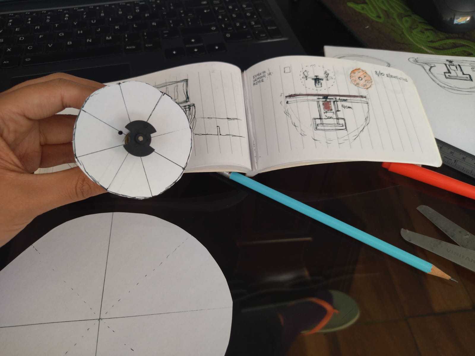
Well, to start with my project, after so many transformations of ideas, I have decided to do it in the following way. As you will see in the images I still keep the idea of generating a spherical product, this time I have decided that, just so that children can manipulate it, the hemispherical shape will have a flexible but resistant texture, the material to be used will be TPU and in turn will protect the inner structure that will contain the connected electronics.
It was important to think about the final shape so as not to allow the part of my electronics not to be exposed and to keep it well protected.
It helped me a lot to take measurements of my components and use paper to recreate a first simple mock-up.💪

Sketches
Paper molds
Paper molds
Paper molds motor part
Paper molds motor part
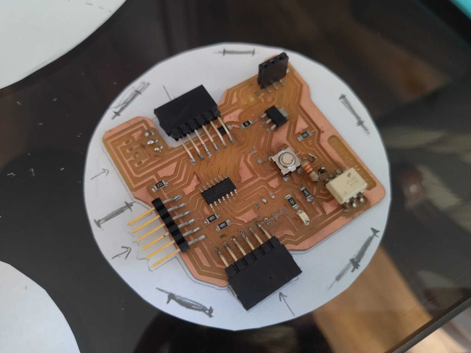
Mold to place my electronic board
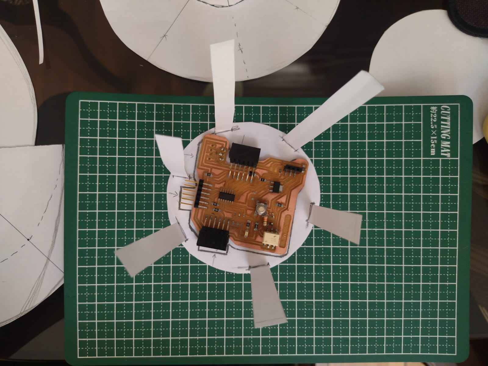
Mold to place my electronic board
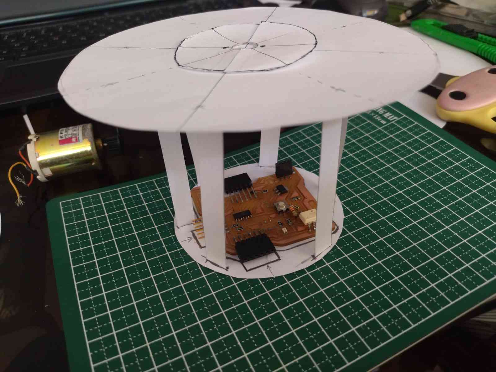
Design to contain motor and electronic board
Design 2D & 3D
As a next challenge, I had to think about the Quentino pieces, so far I had thought of some solutions but not in detail so as I have already decided to do laser cutting and 3D printing, to be able to make the fabrication, I must enlist my pieces in digital, below I share part of the designs and views in 2 and 3 dimensions. 💪

Sketches

3D Printing Position

First schematic in rhino

3D Printing Position

Parts for laser cutting

Piece in MDF

Grip position

Superior 3D printed part

Part to connect the motor

Forming the piece

Location of the characters

Parts ready

All my pieces

The form of Quentino

Manufacturing
As part of the process, digital fabrication could not be missing. My first attempt was with 3D printing, I used TPE because I want my project to be flexible for the manipulation that children can give it. Below I share images and videos of the 3D printing process.💪
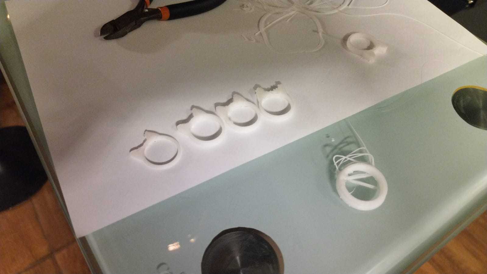
TPE Test 1
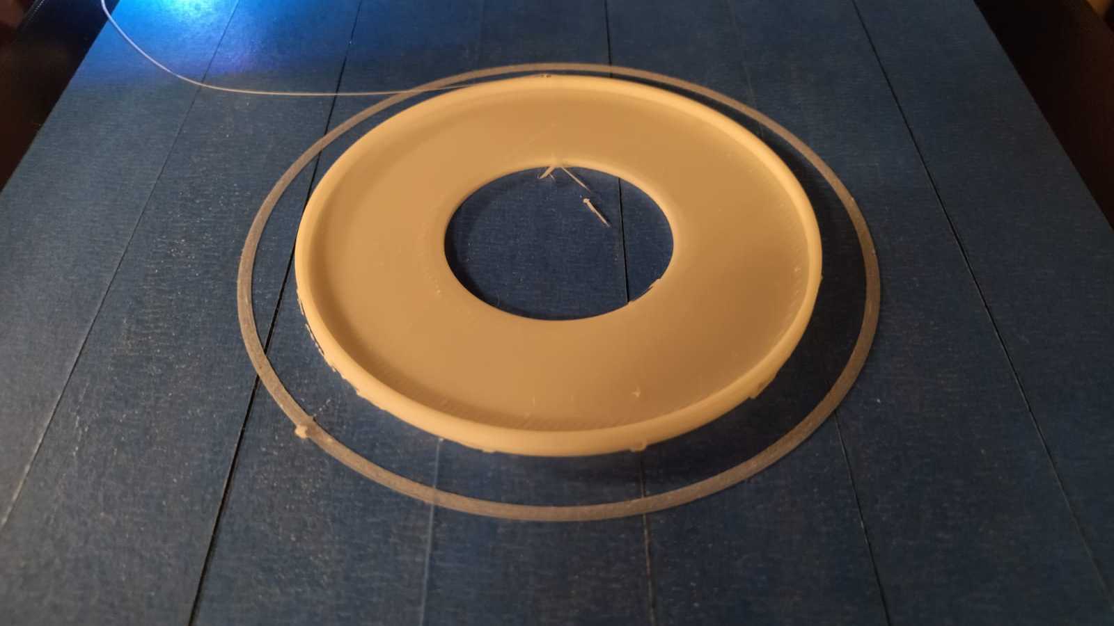
TPE Test 2
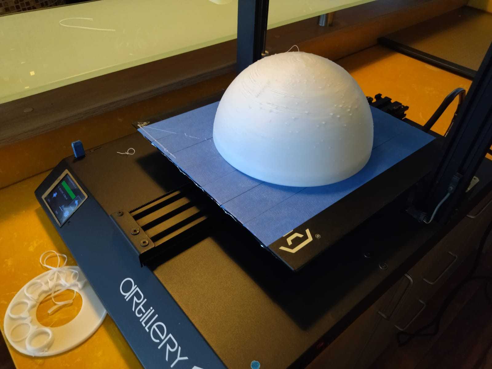
First base piece
100%
First base piece
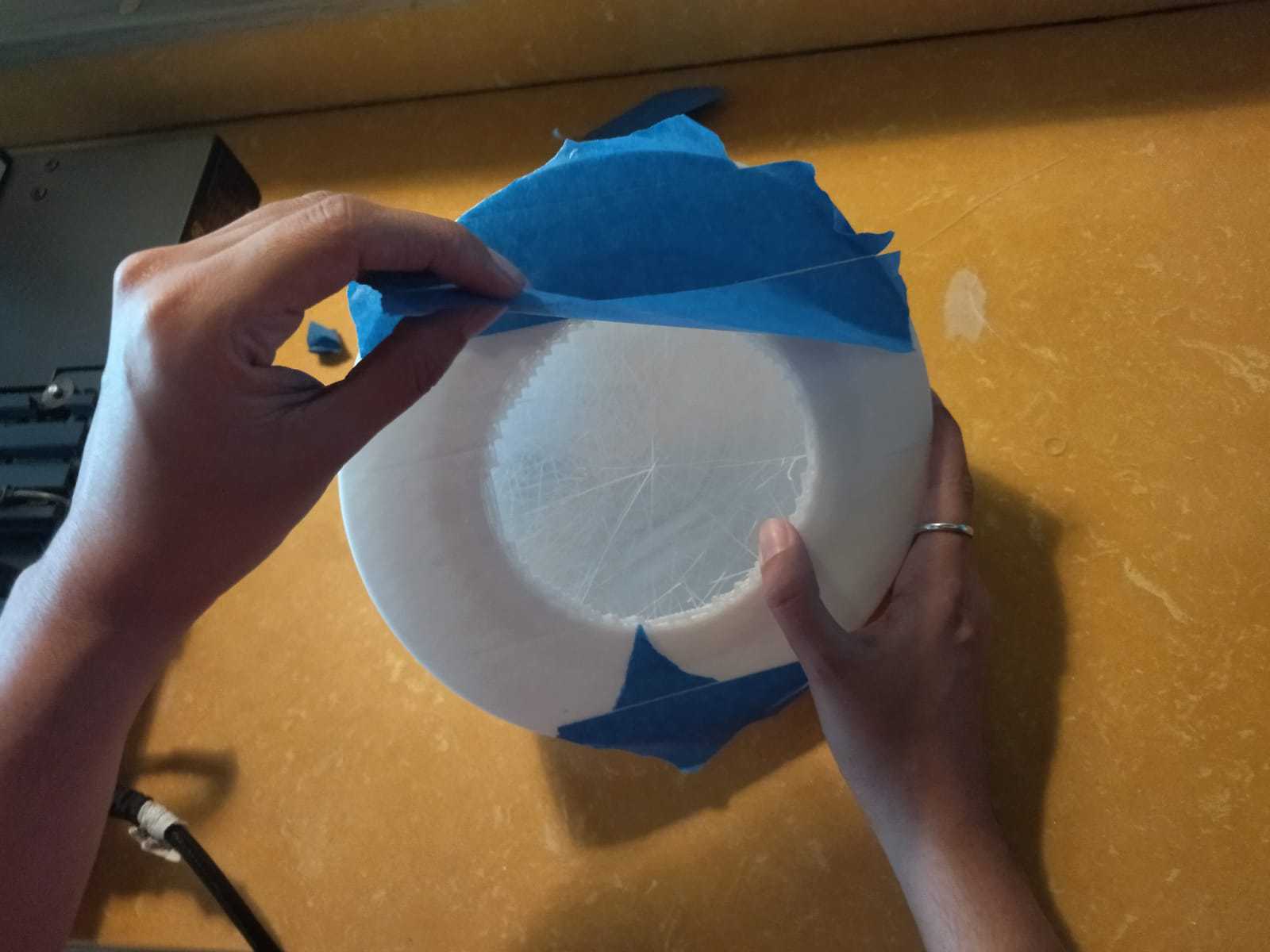
Taking off
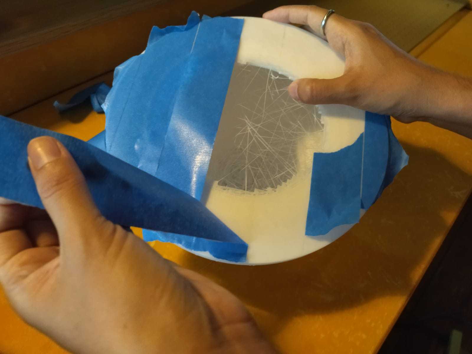
Taking off
After my piece printed in TPE, I proceeded with the top piece in PLA material, I chose an orange color so that it can be differentiated from the base and look more colorful. Next I show the images of its fabrication.
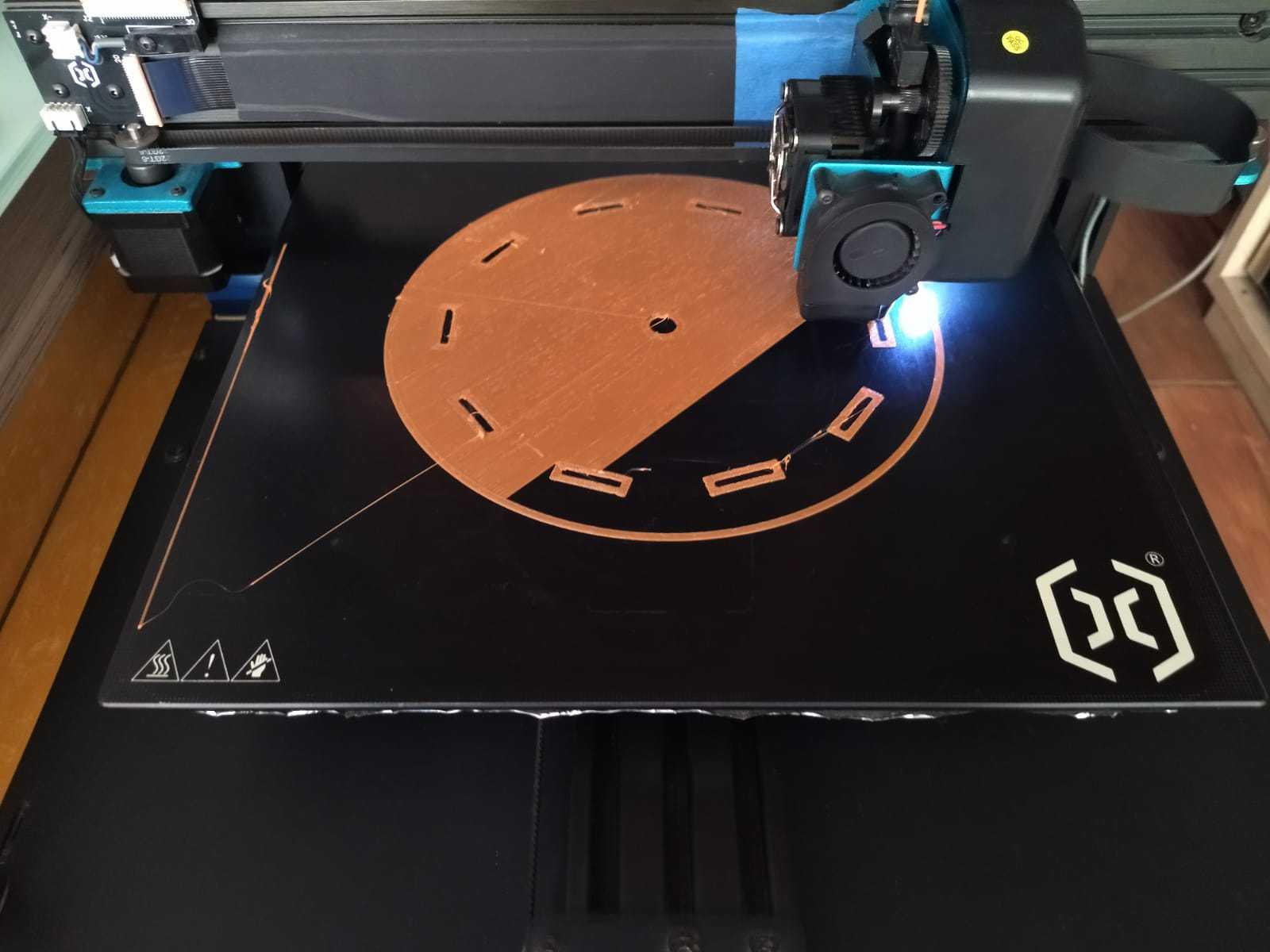
First layer
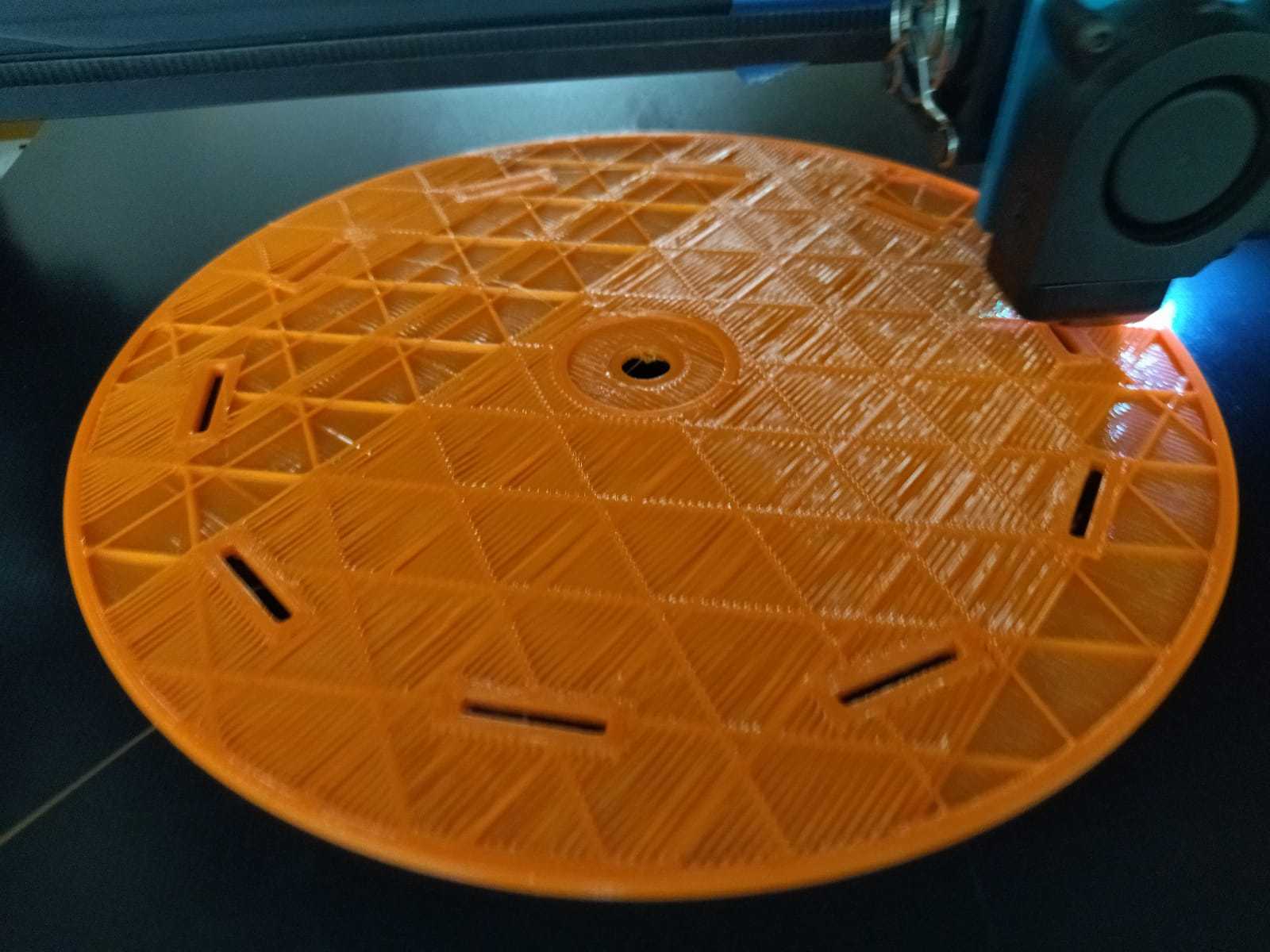
Taking off
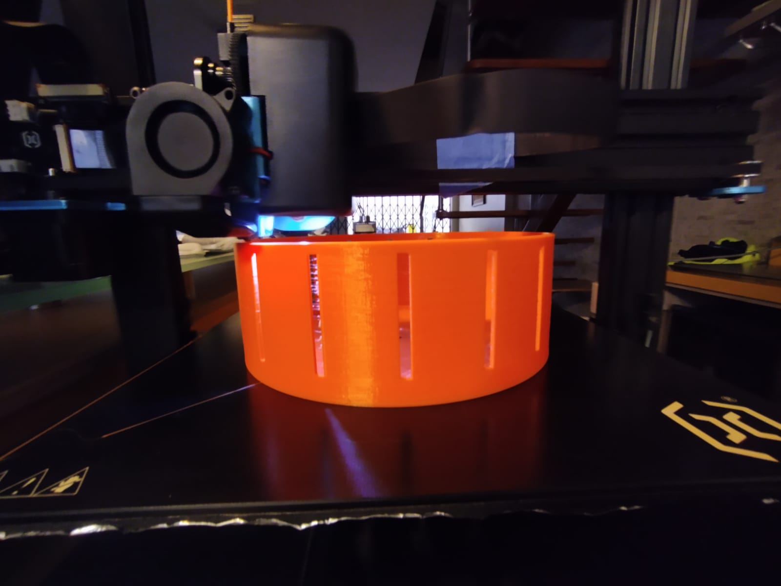
Almost there
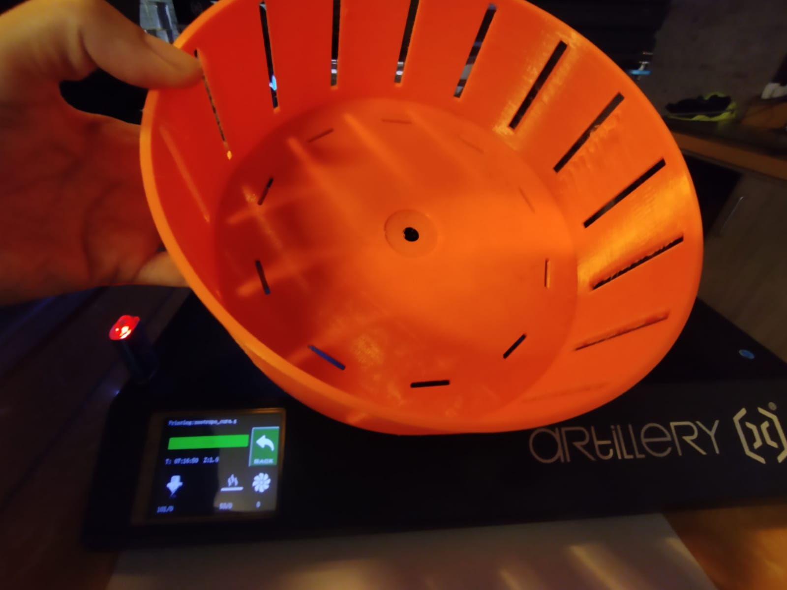
Piece ready!
Orange piece
Now I have to make the part that will join the motor to the orange disc. This stage was not easy, I had to make several tests because the motor I use has a very thin end where originally there is a black piece that is used to anchor any piece that wants to rotate. To replace it, I made a simpler design and adaptable to my big orange piece. Below I show the tests.
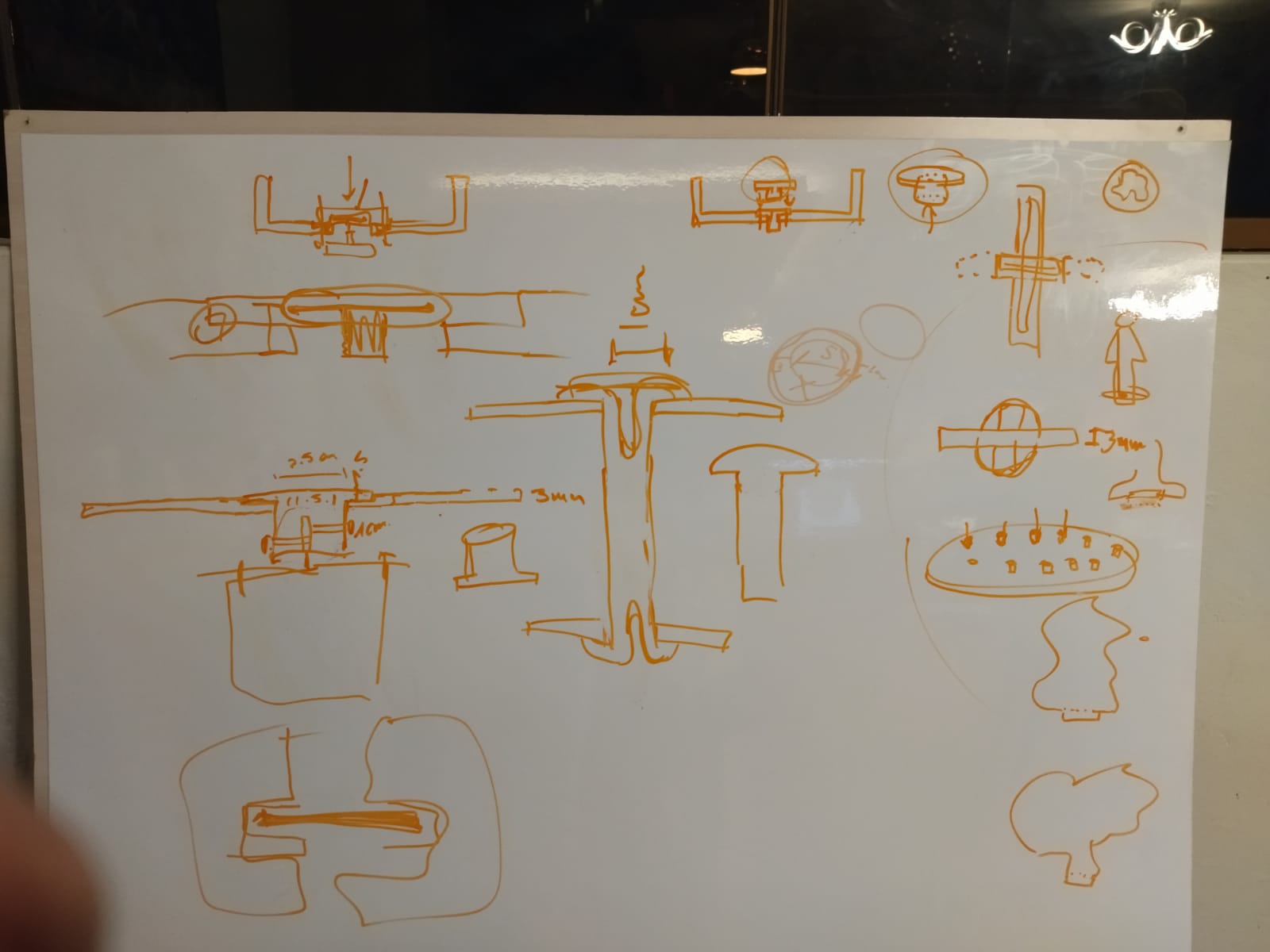
Sketches
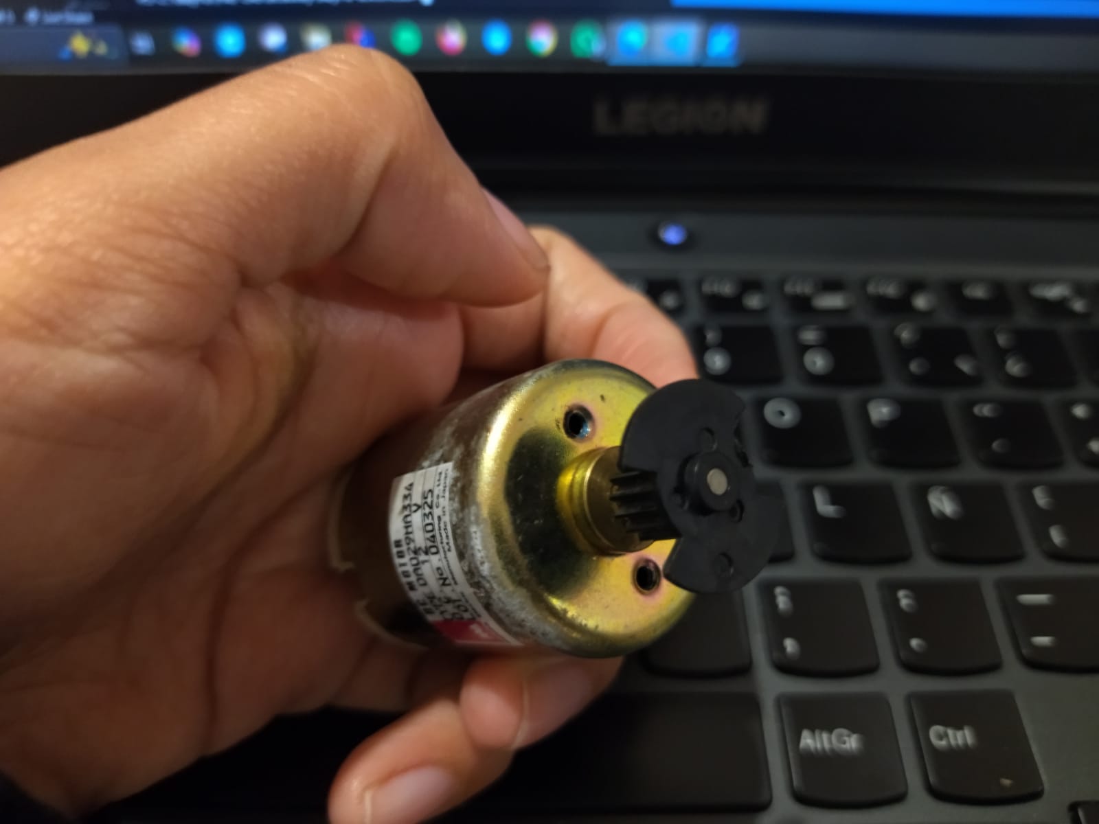
Engine with original part
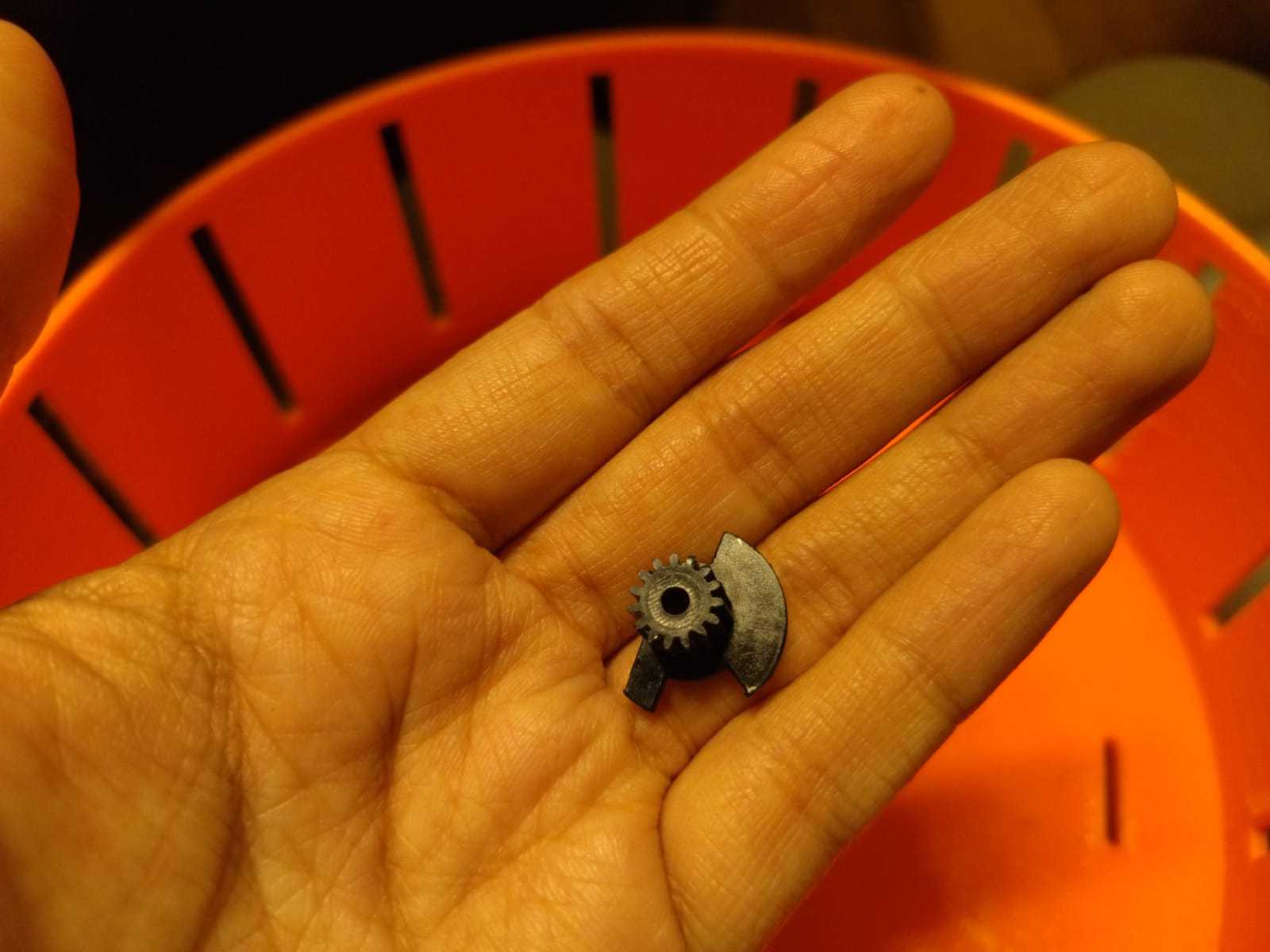
Small black piece
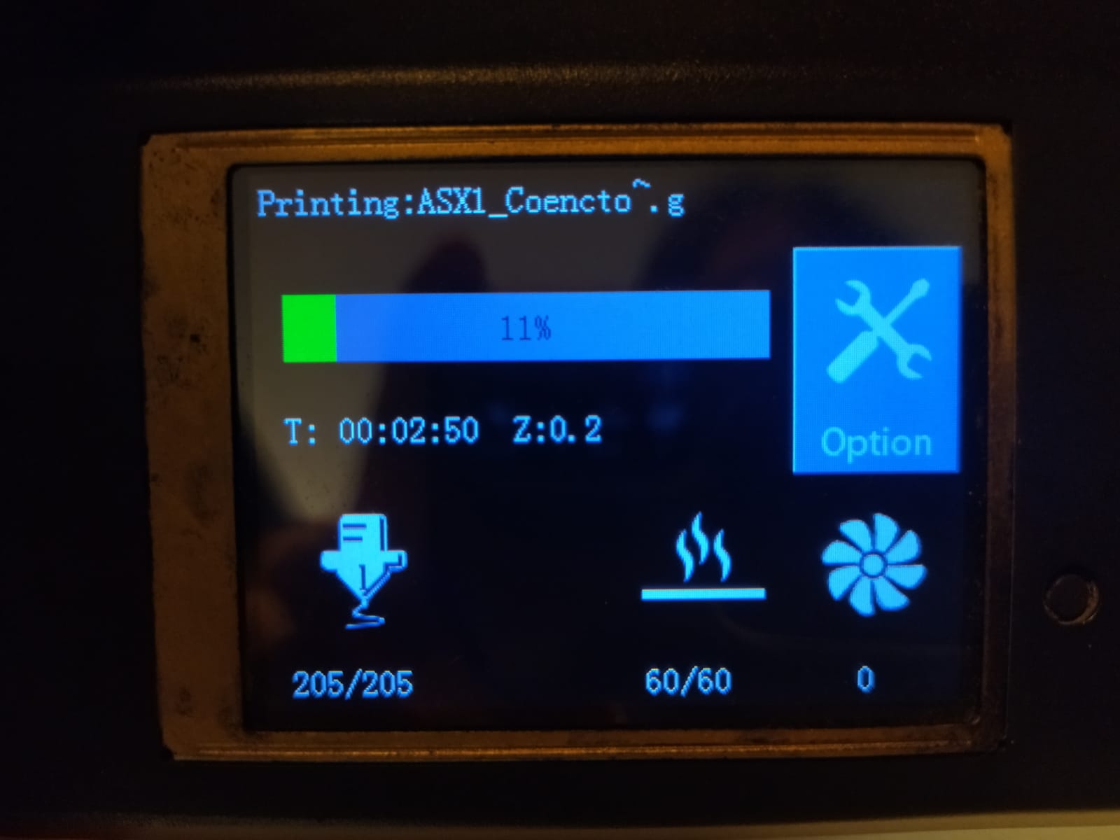
Printing progress
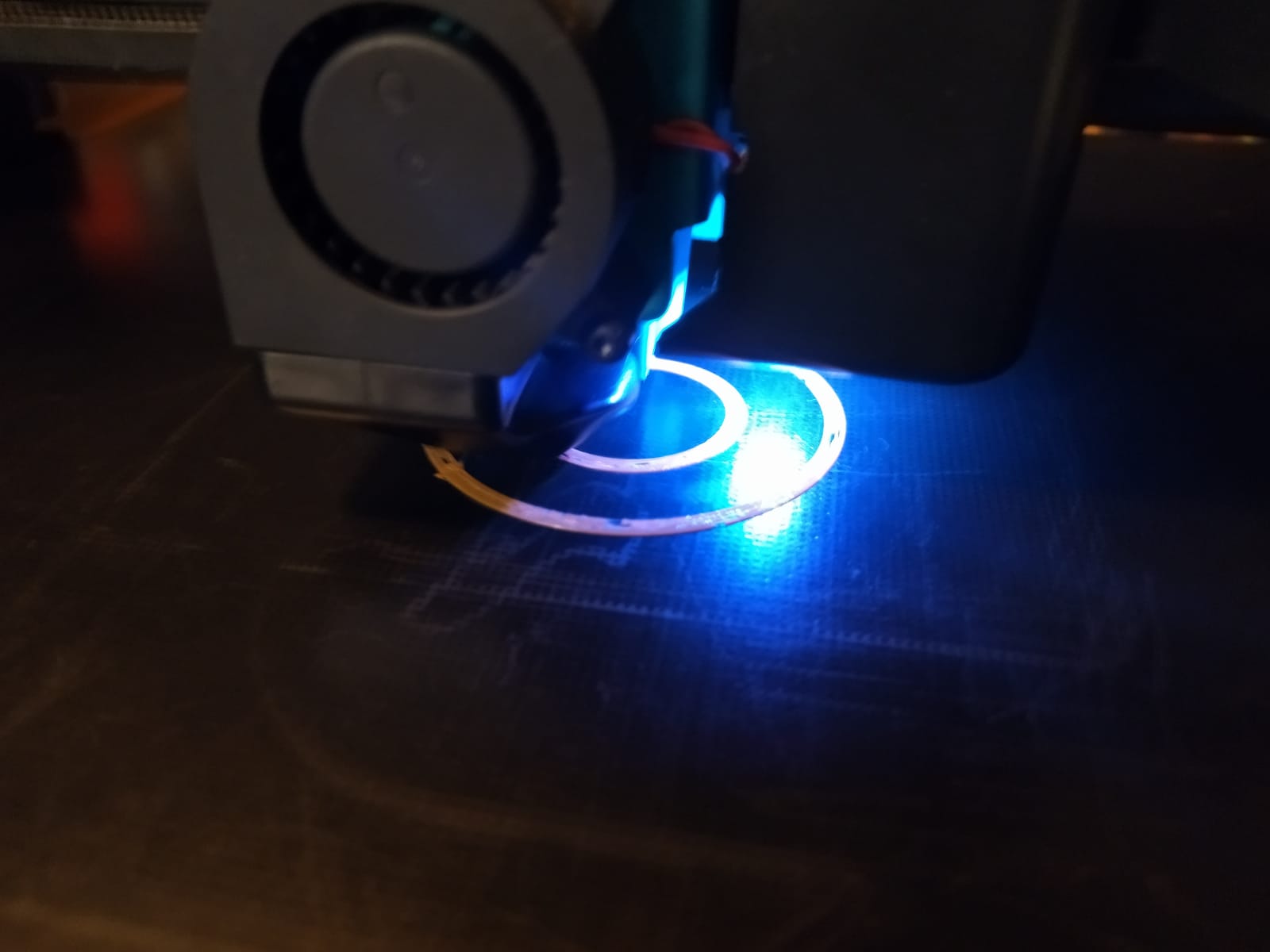
Printing progress
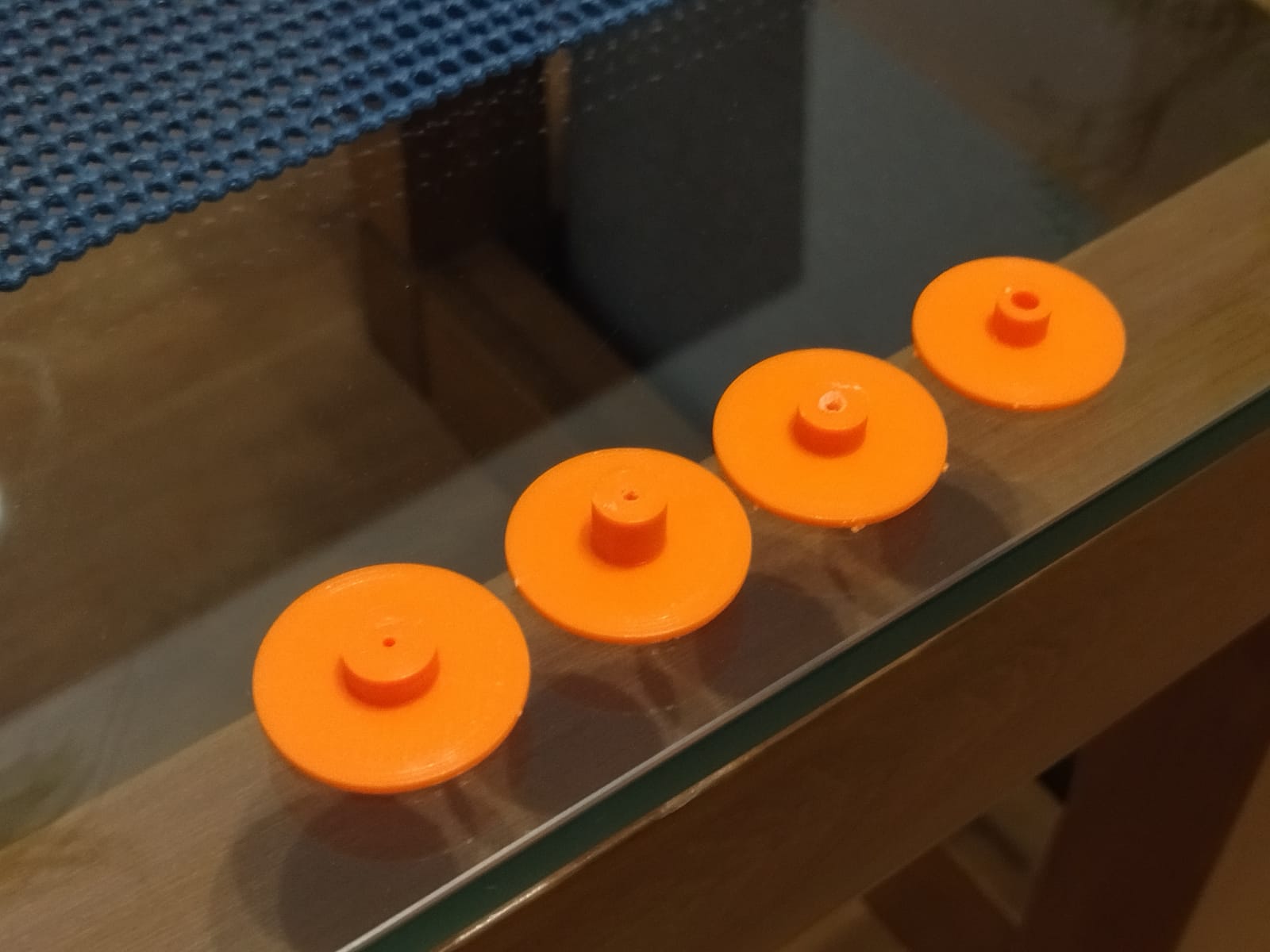
All tests
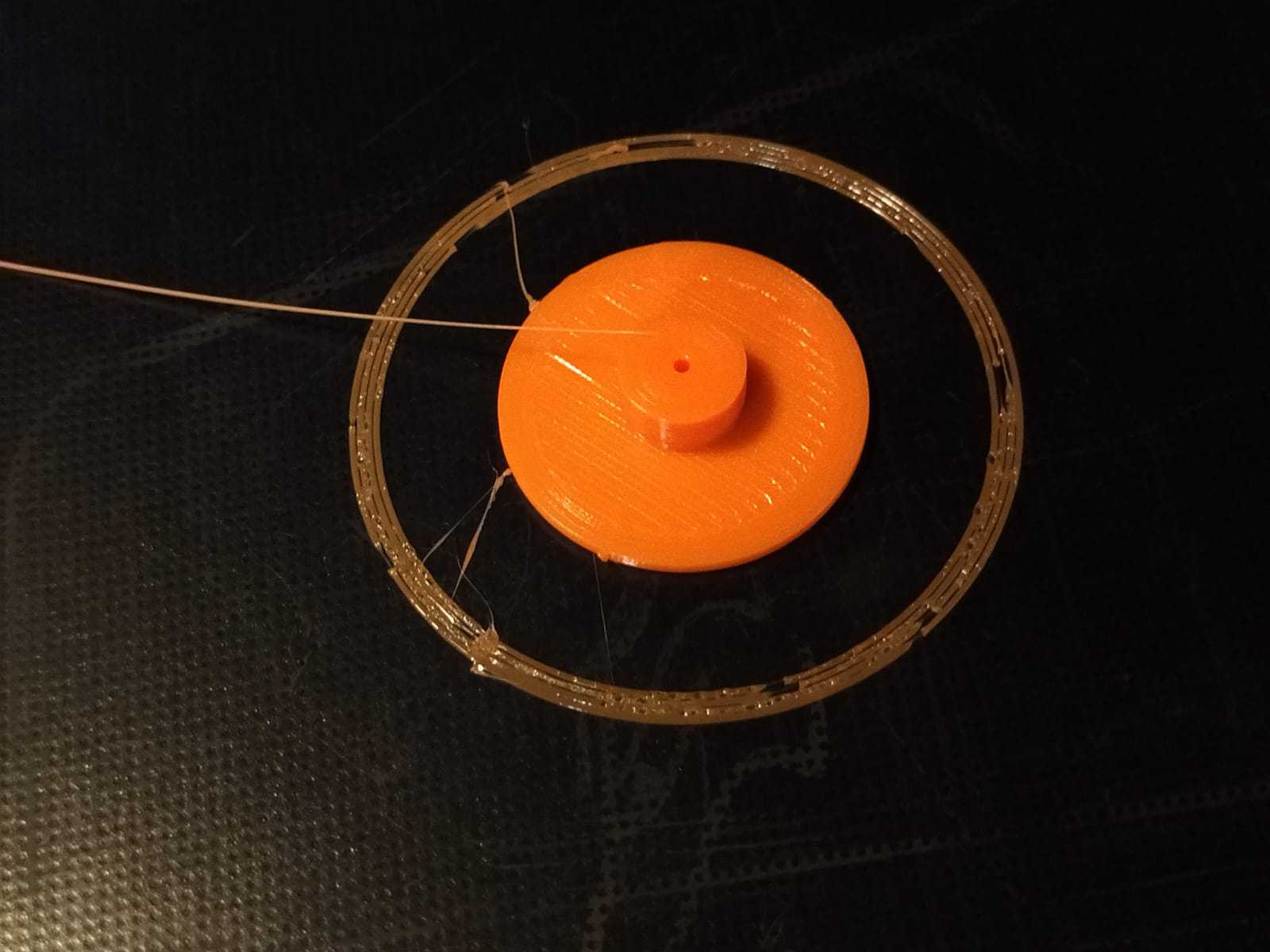
Final test piece
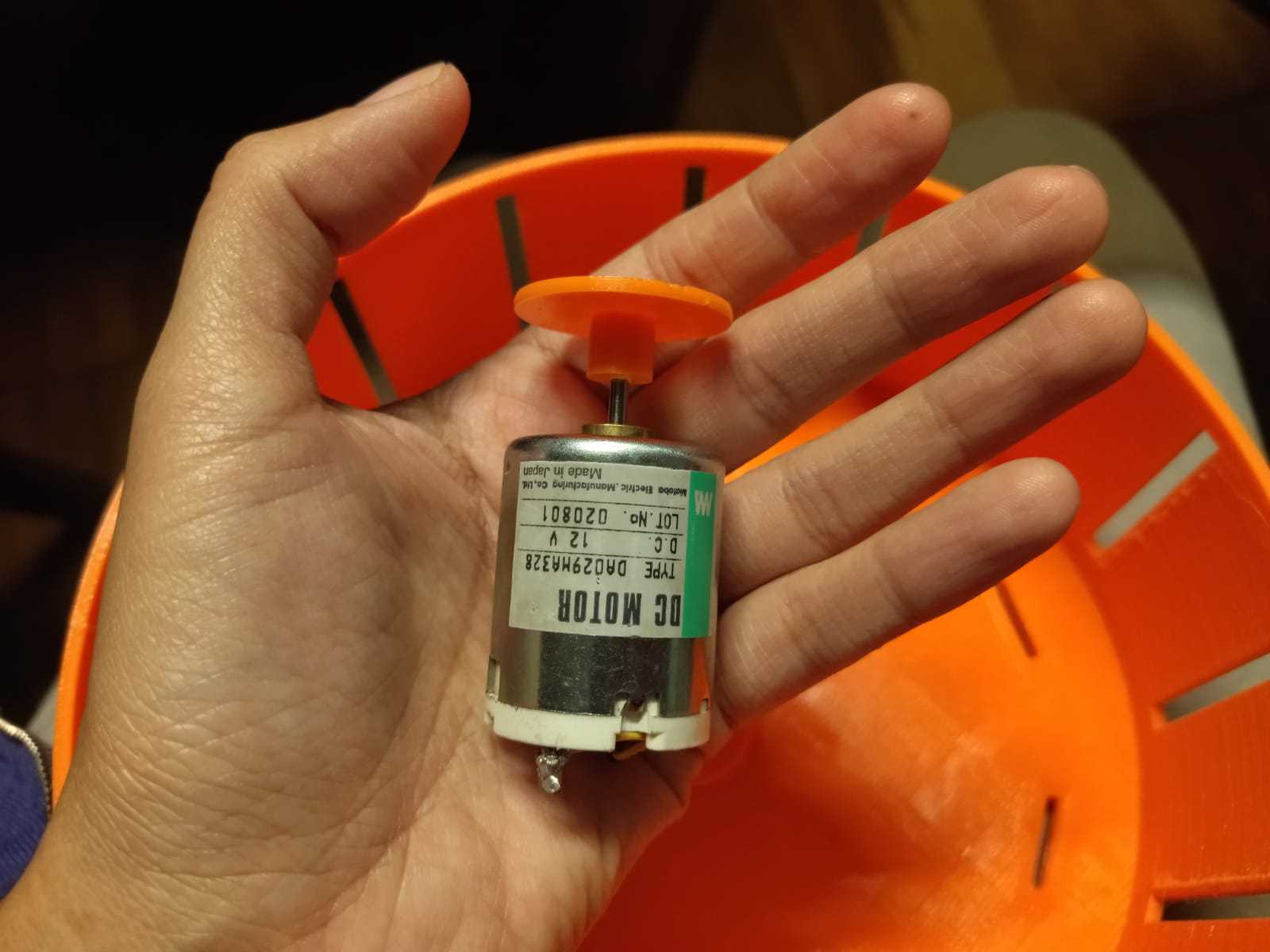
Connected part!
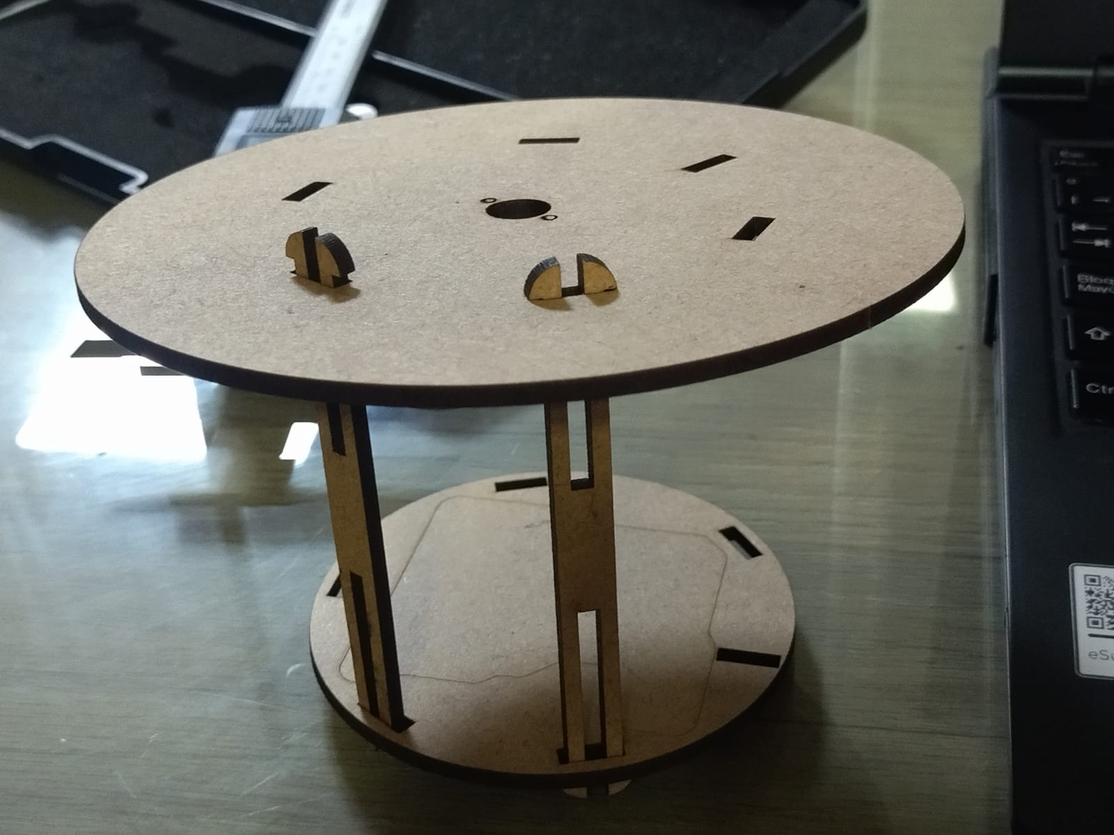
As a next step I had to manufacture the structure that would contain all my electronics, it was very important to get my board, components and cables are protected because the user should not have direct contact with any of these parts. I had to make tests until I reached the optimal shape, on the way I had to redesign an important piece that I will show you next.
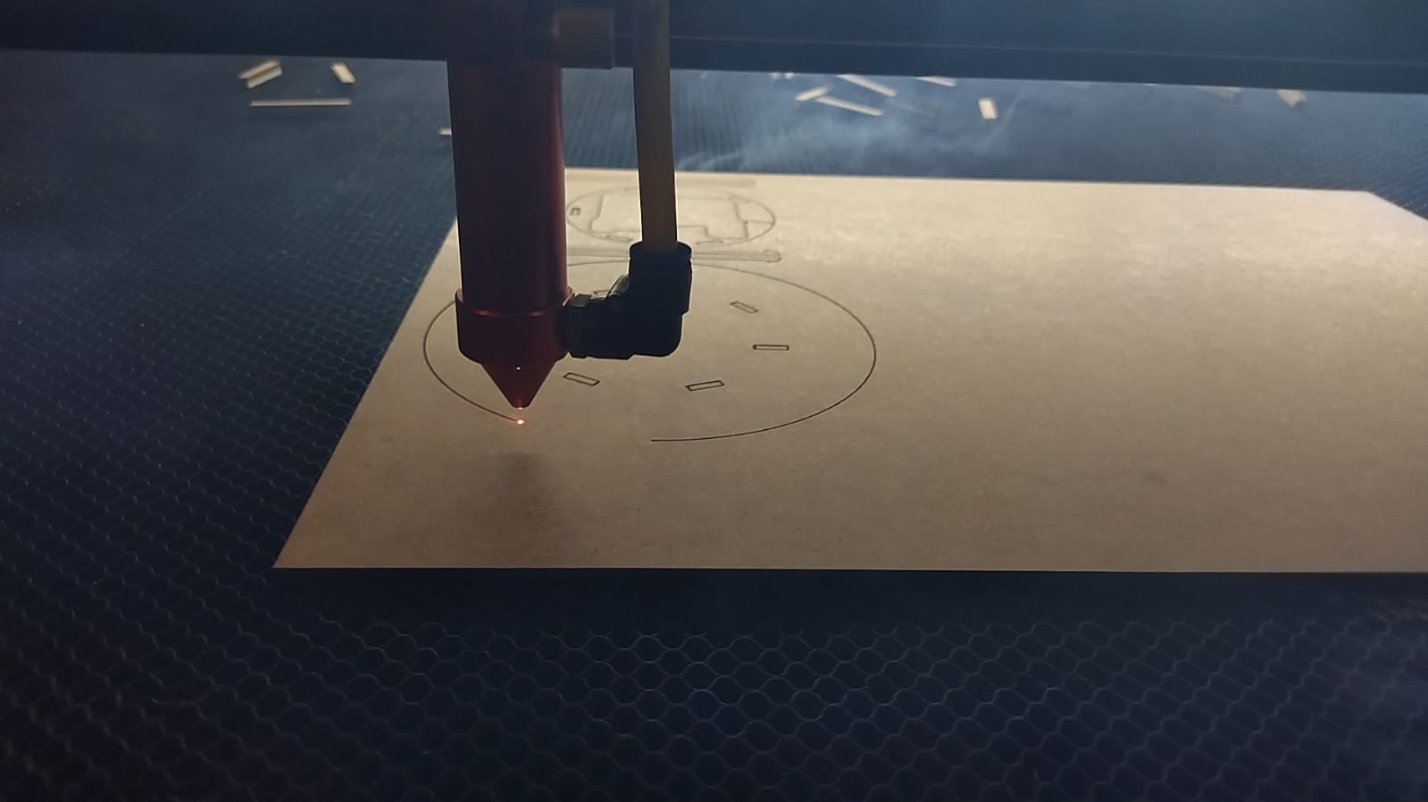
First piece
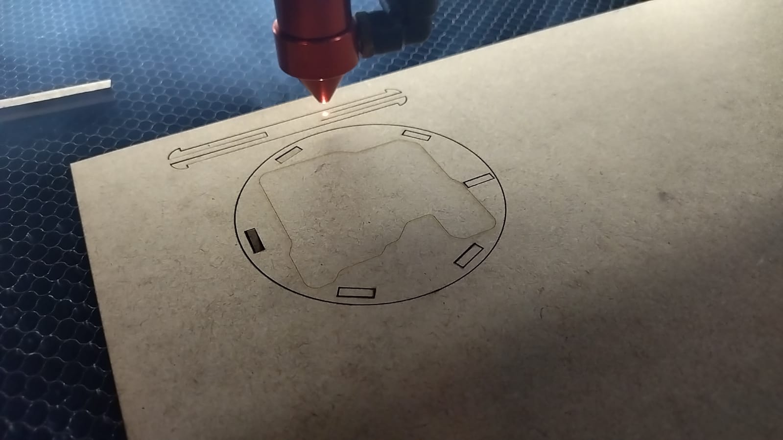
Second piece
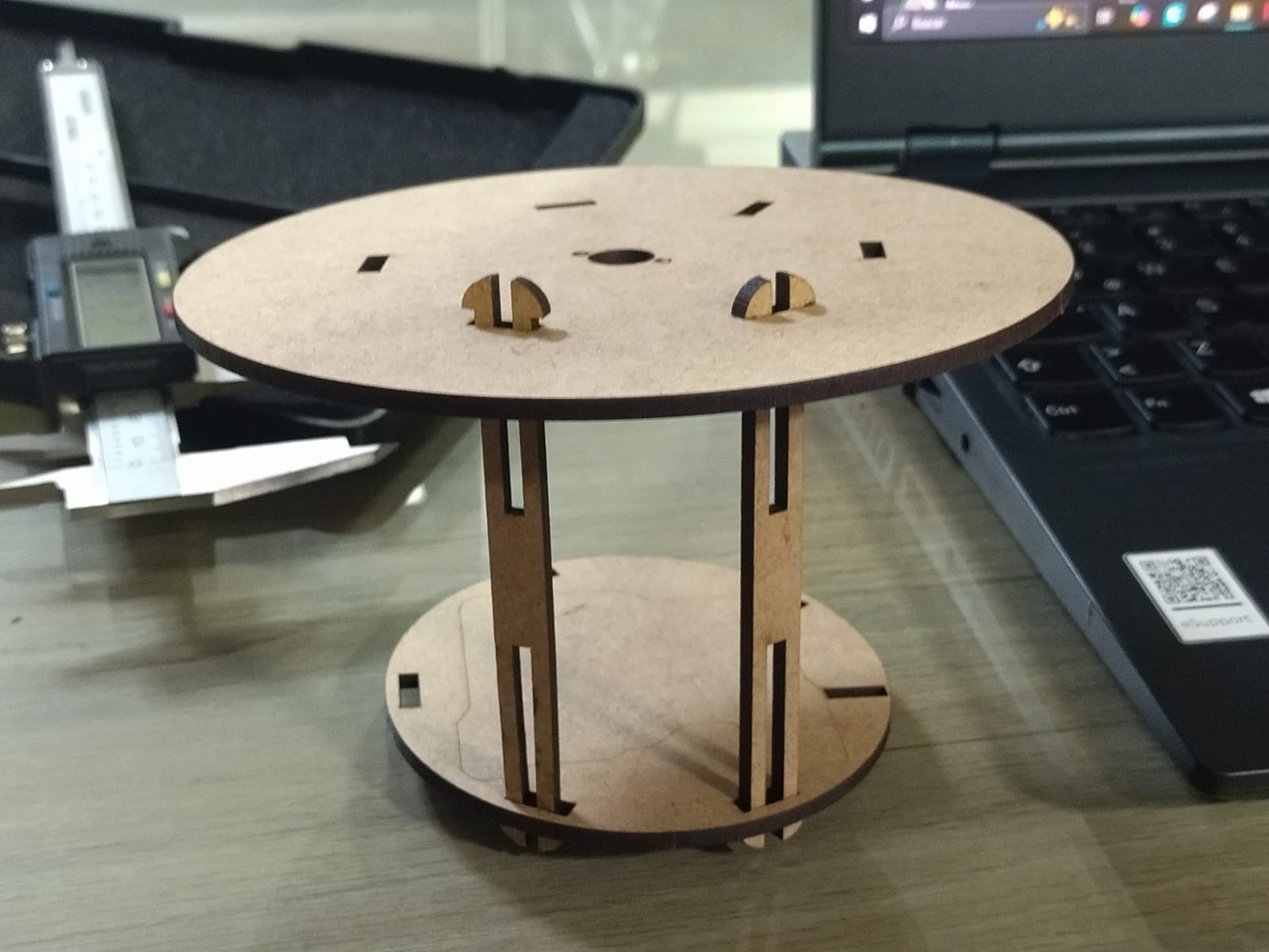
Test 1
Test 1
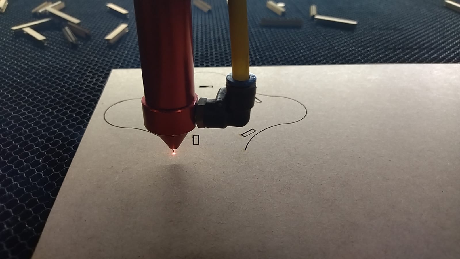
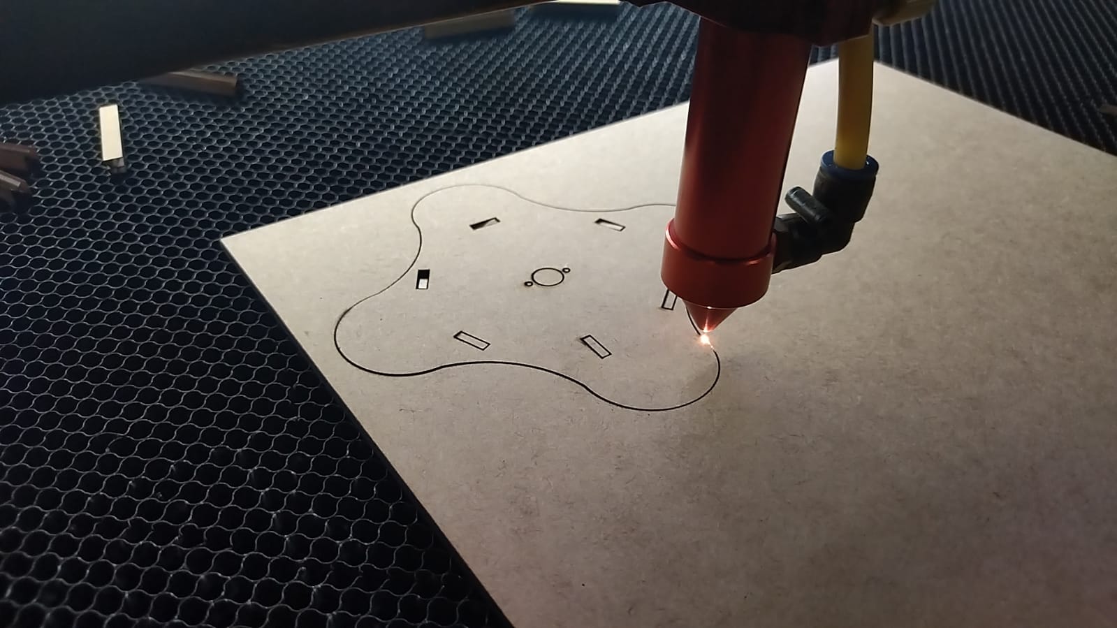
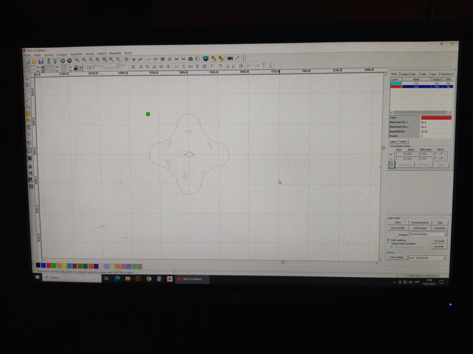
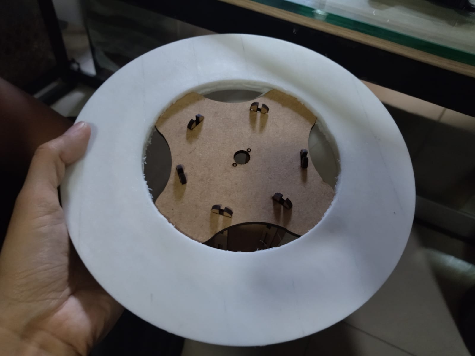
When I made the first test I realized that the top piece did not enter easily into the TPE hemisphere, the intention is that it can be embedded to be able to hold. To solve this I changed the design and made some curves. Below I show the difference and the assembly test.
New model
New model
File
Test
Electronics
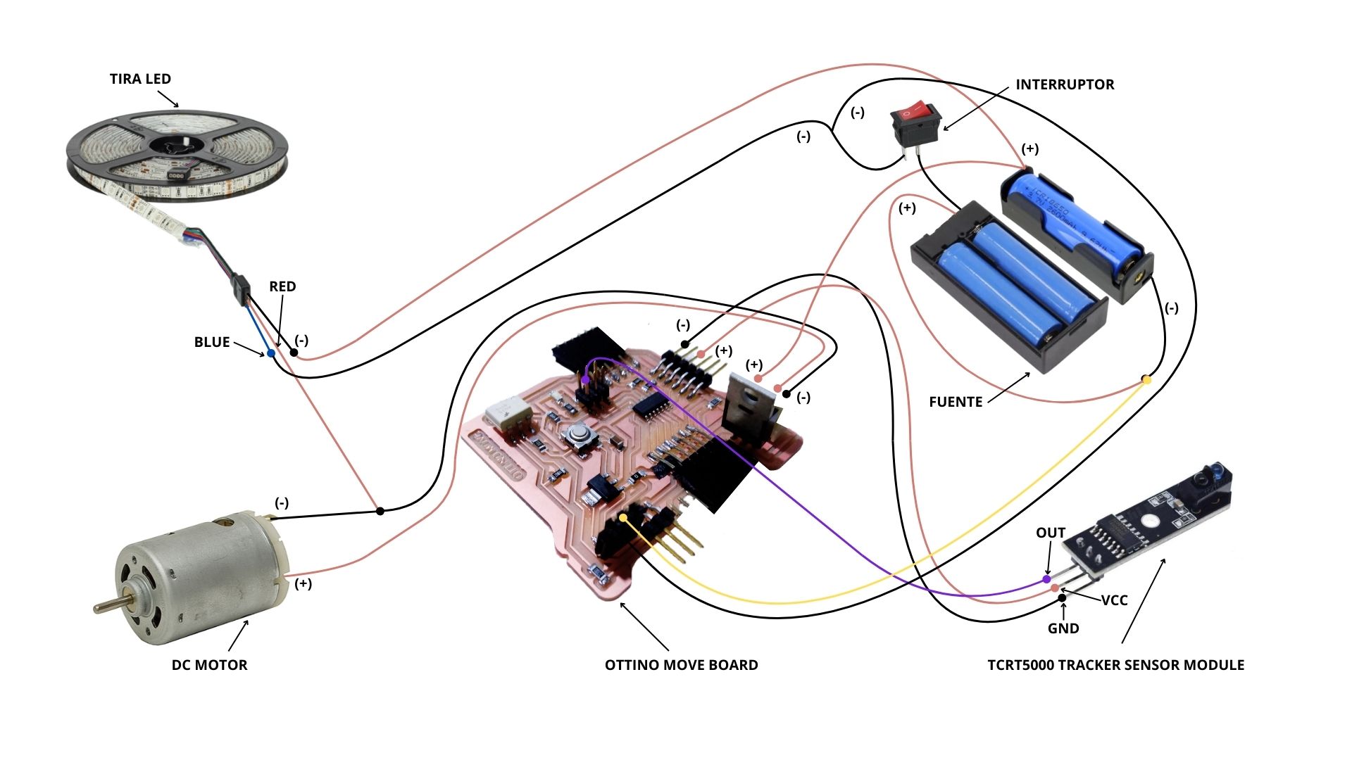
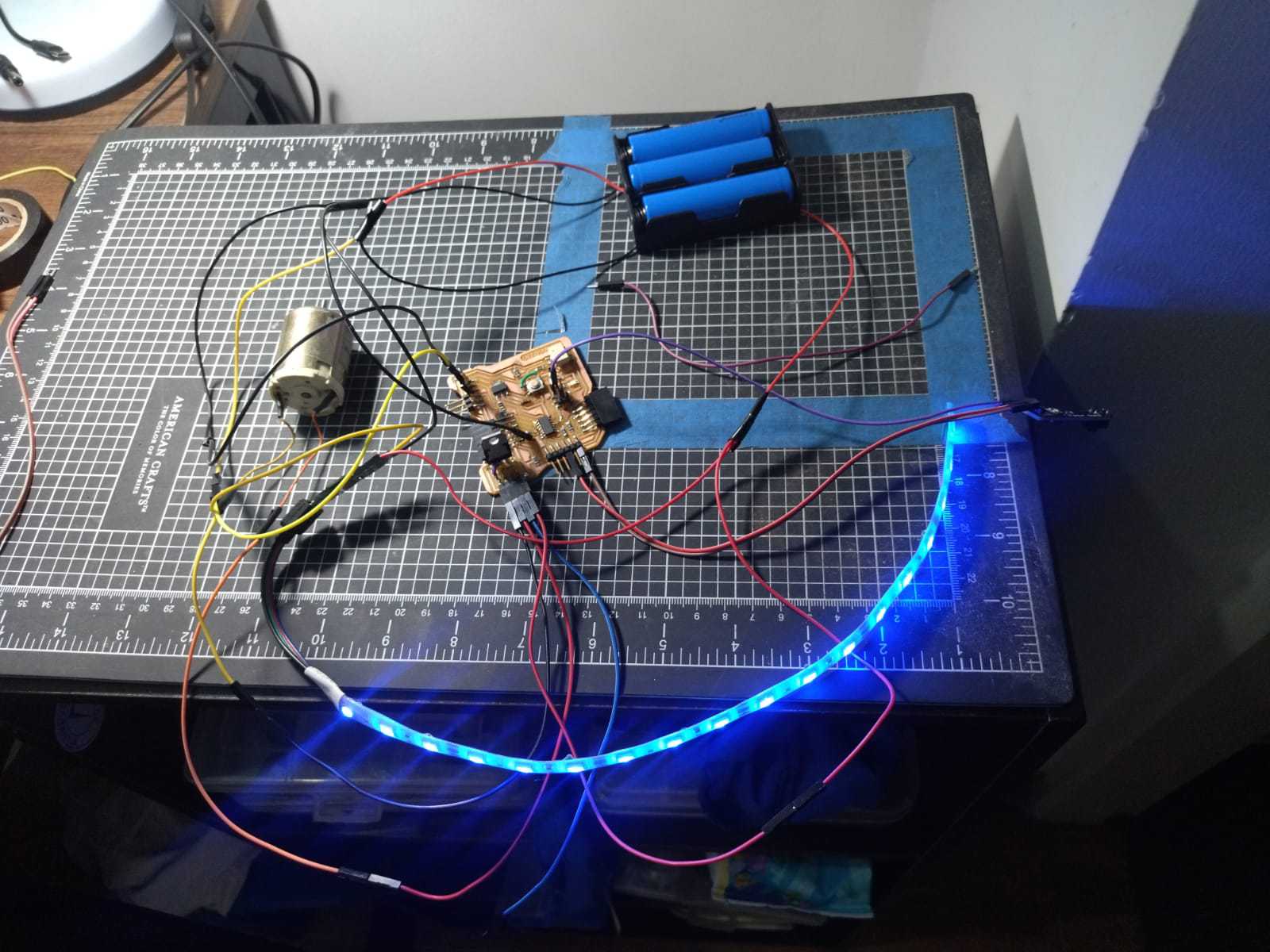
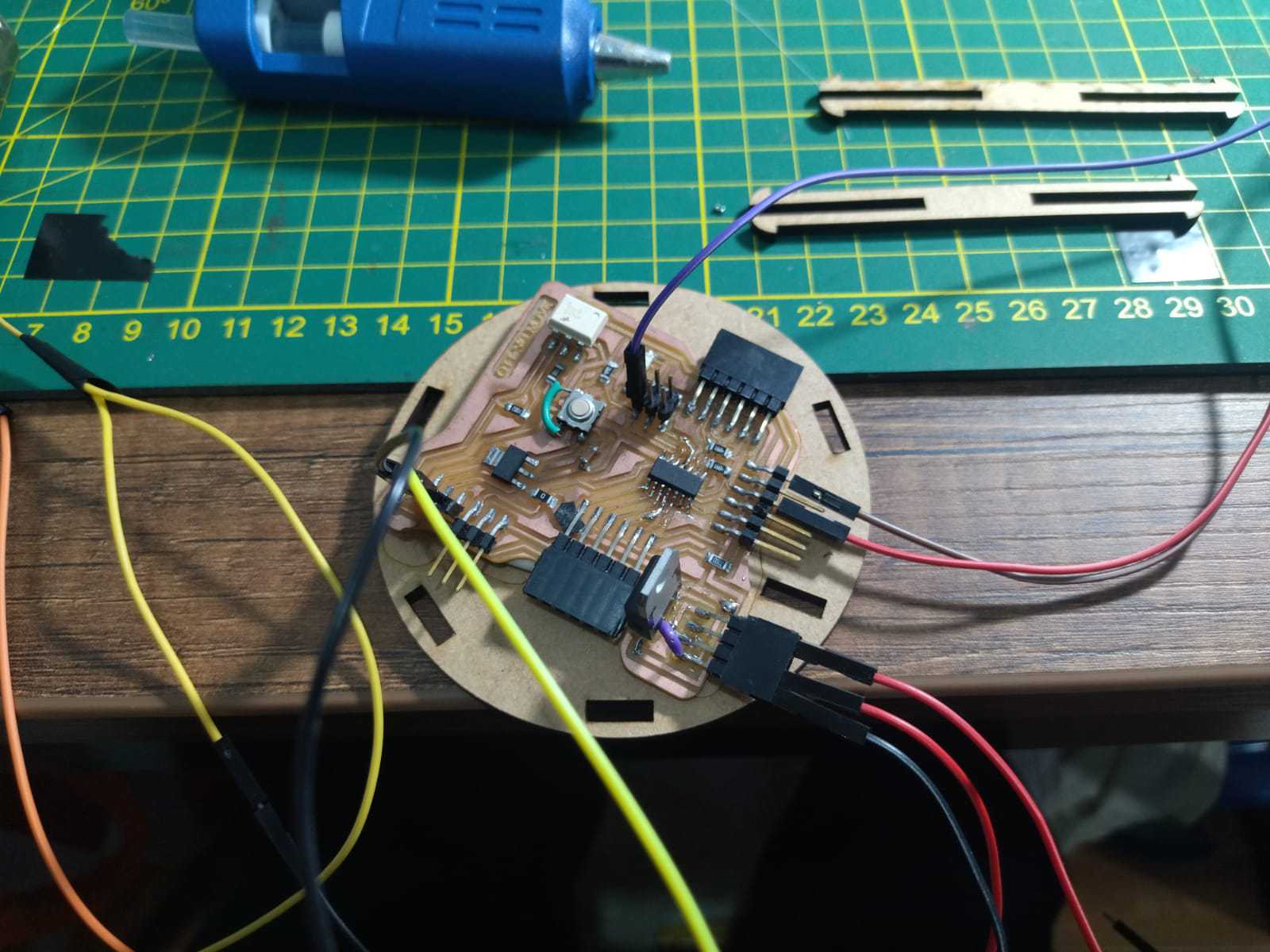
To solve the electronic part of my project, I have to use my “Ottino move” board, I designed this board during the “Electronic Design” week and it allowed me to consider the operation for Quentino from the beginning. My board will connect a motor with an infrared sensor and a led strip. When the infrared sensor detects the signal, the motor will turn on in conjunction with the lights. To better explain the operation I will show a schematic of the connections, also, I will show how I fit my electronics with the MDF structure I designed for it, join me to see this process!
Electronic system test
Electronic system test
Board location
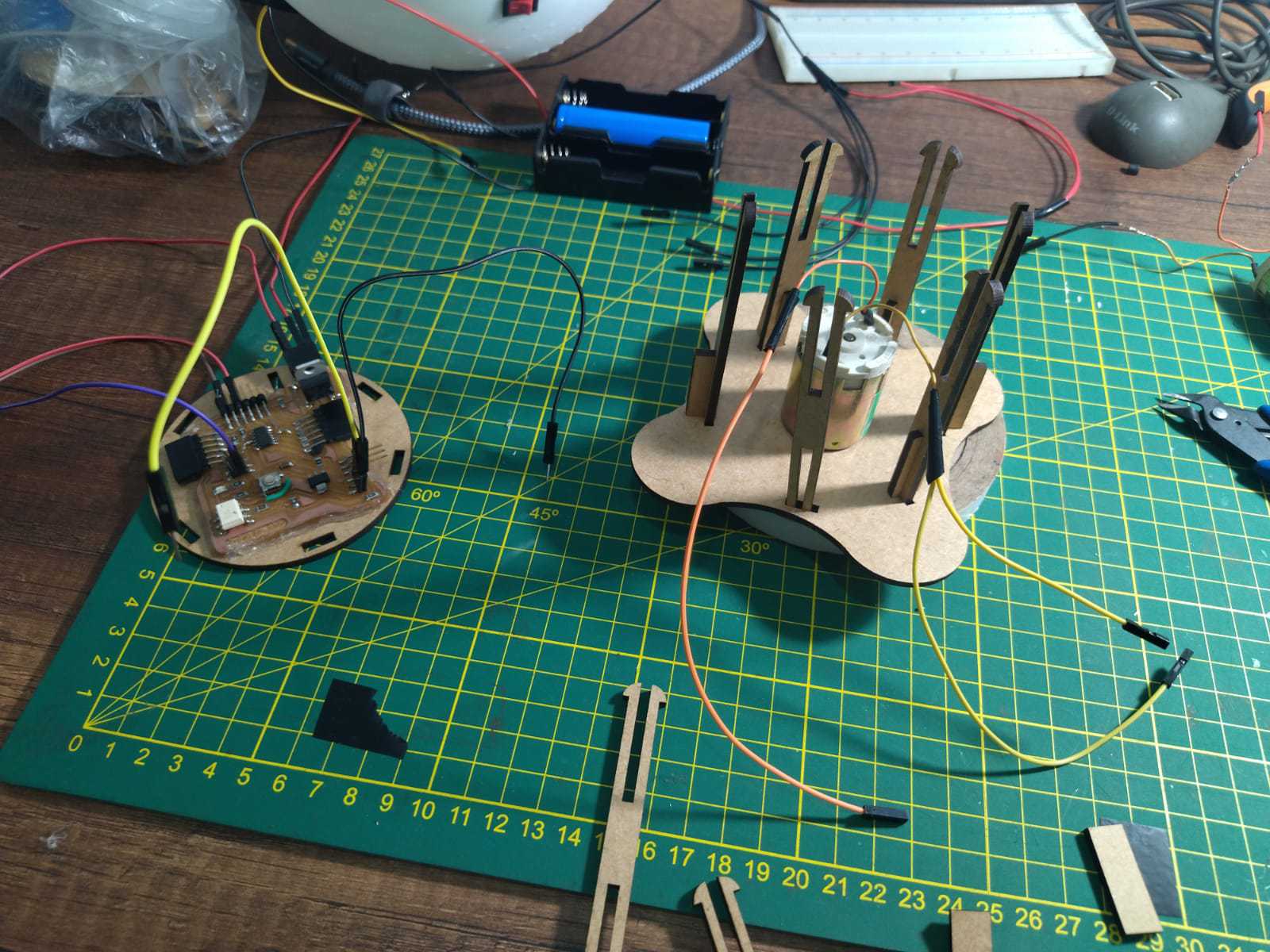
Motor location
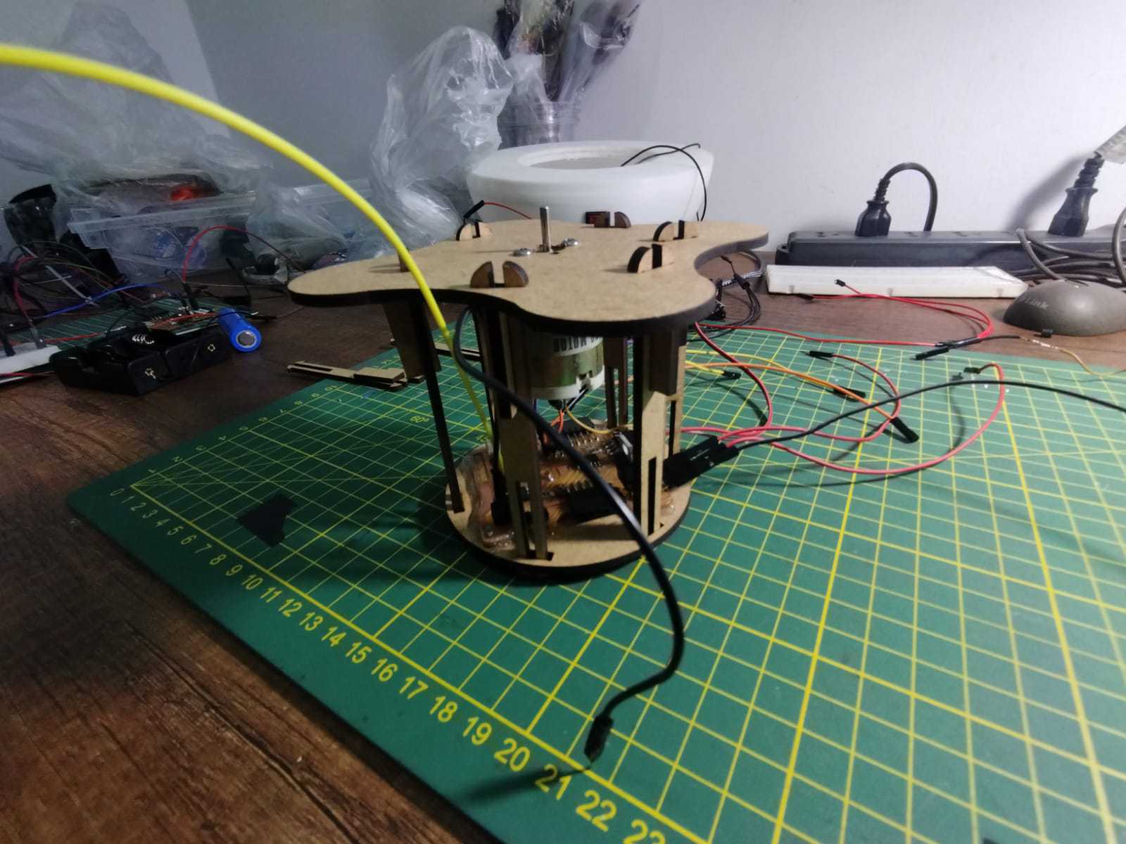
Complete case
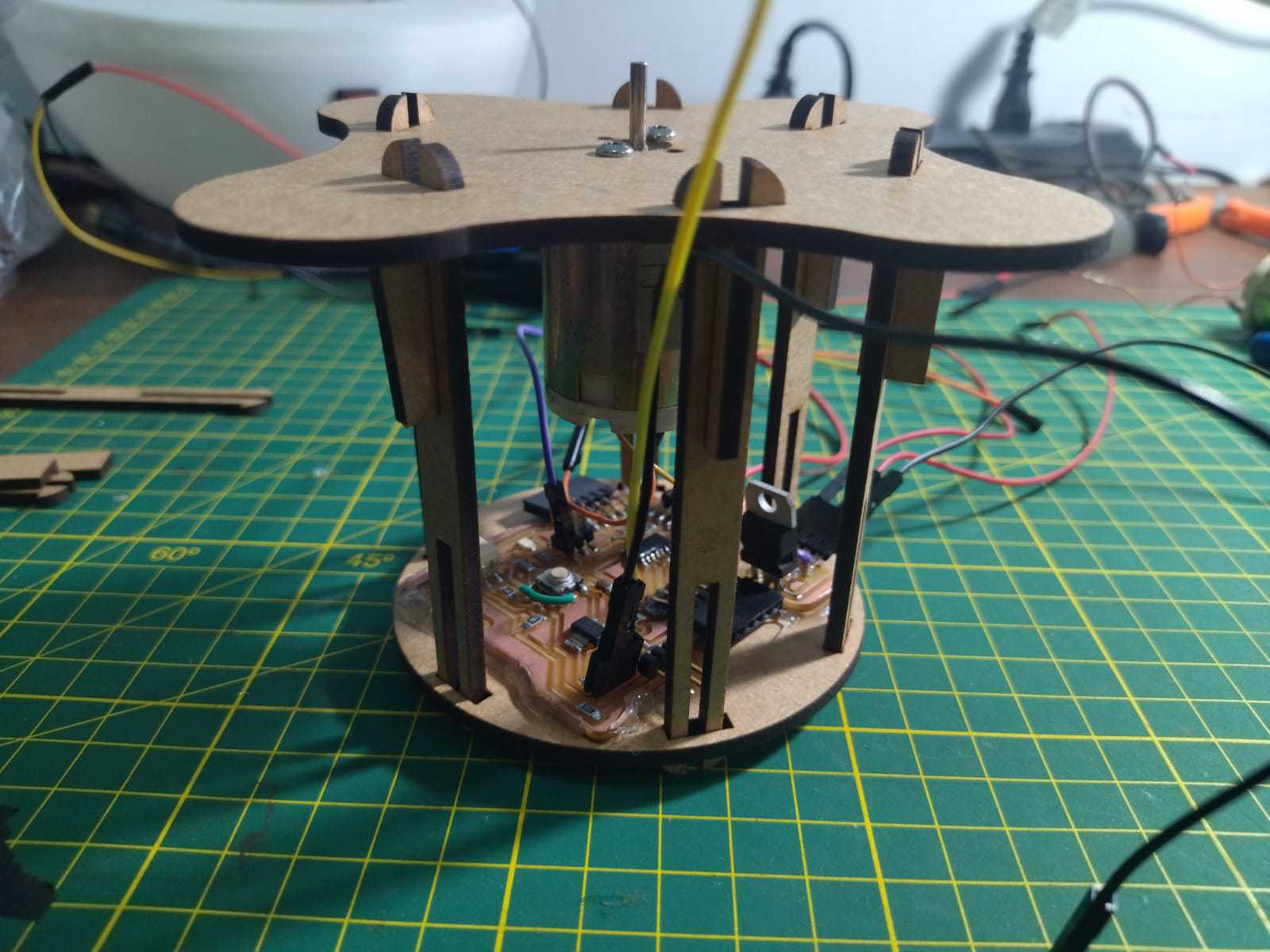
Complete case
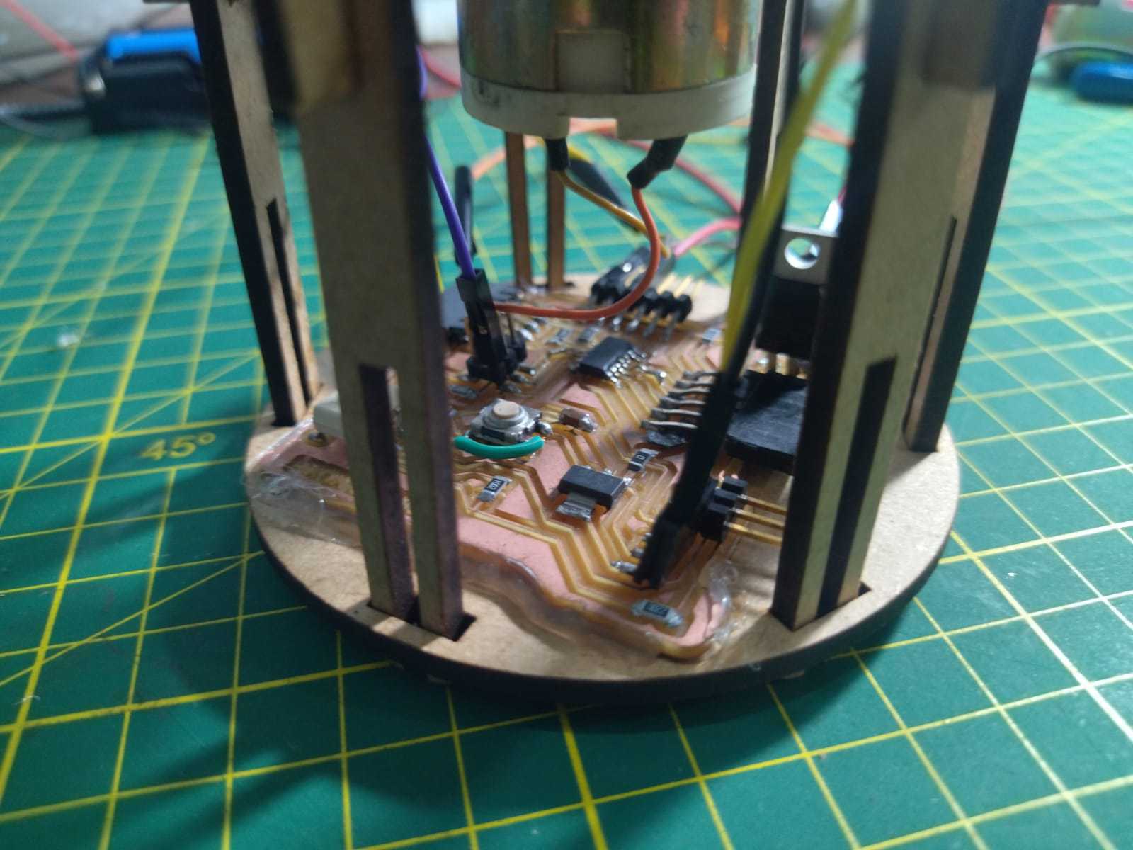
Complete case
Programming
To make Quentino work I decided that the logic is to first turn it on with a switch, this will allow it to more safely turn the device on and off. Then the internal lights will turn blue, this is the indicator that the device is on. The next step to turn the plate is to bring the hand close to the infrared sensor, which when activated causes the LED to change to magenta and the motor to start turning. Once that happens, the upper plate will rotate as long as the infrared sensor remains activated, according to the user's preference. To achieve this sequence I used the following programming:
// Mayra Ascencio Calderón
// Fab Academy
// Code

const int sensor = 10;
const int led1 = 8;
const int motor = 2;
int sl;

const int pinservo1=1;

void setup() {

	pinMode (sensor, INPUT);
	pinMode (led1, OUTPUT);
	pinMode (motor, OUTPUT);

}

void loop() {

	sl= digitalRead(sensor);

	if (sl==1)
	{digitalWrite (led1,HIGH);
	digitalWrite (motor,HIGH);

	}
	else
	{
	digitalWrite(led1,LOW);
	digitalWrite(motor,LOW);
	}

	delay(20);

	}
System imtegration
Quentino is an integration of many processes, among them is the semi-spherical base made of TPE, the internal MDF structure to contain and organize the electronic circuit, the connection of the upper parts with the motor which is the main element that generates the rotation of the upper platform, and finally the circular platform with the openings that allow the visualization of the embedded elements. Next I show the assembly between the parts step by step to be able to build Quentino!
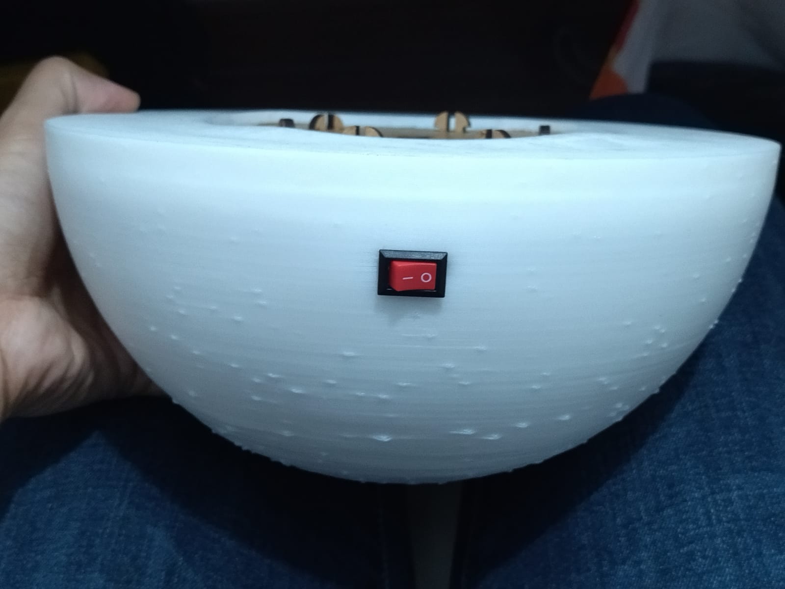
Button located
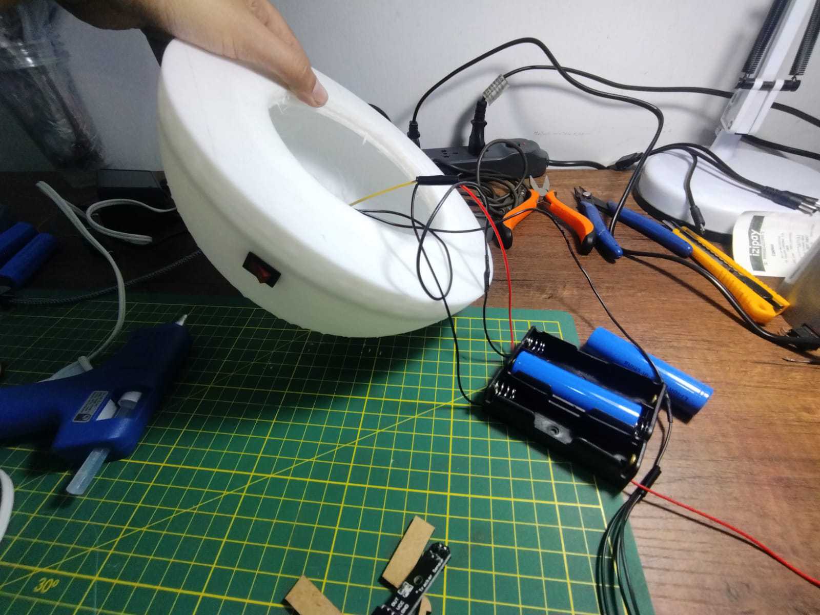
Button connected to source
Electronic system test
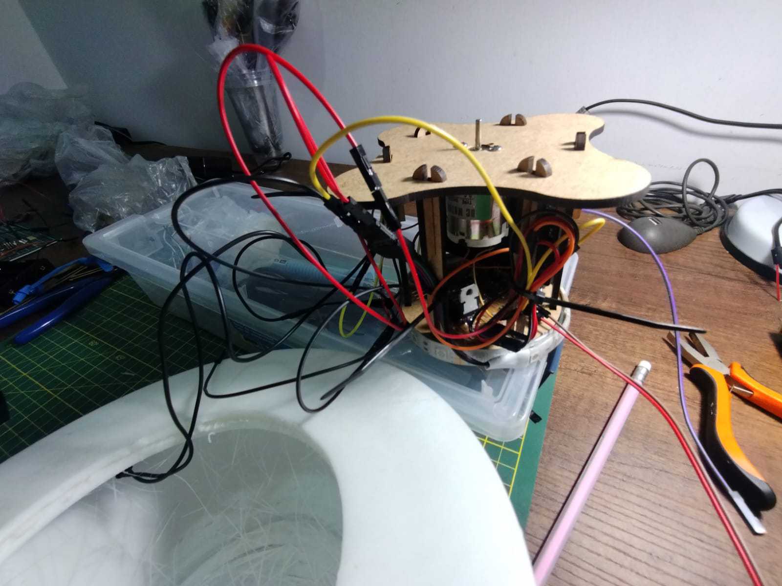
Electronic system test
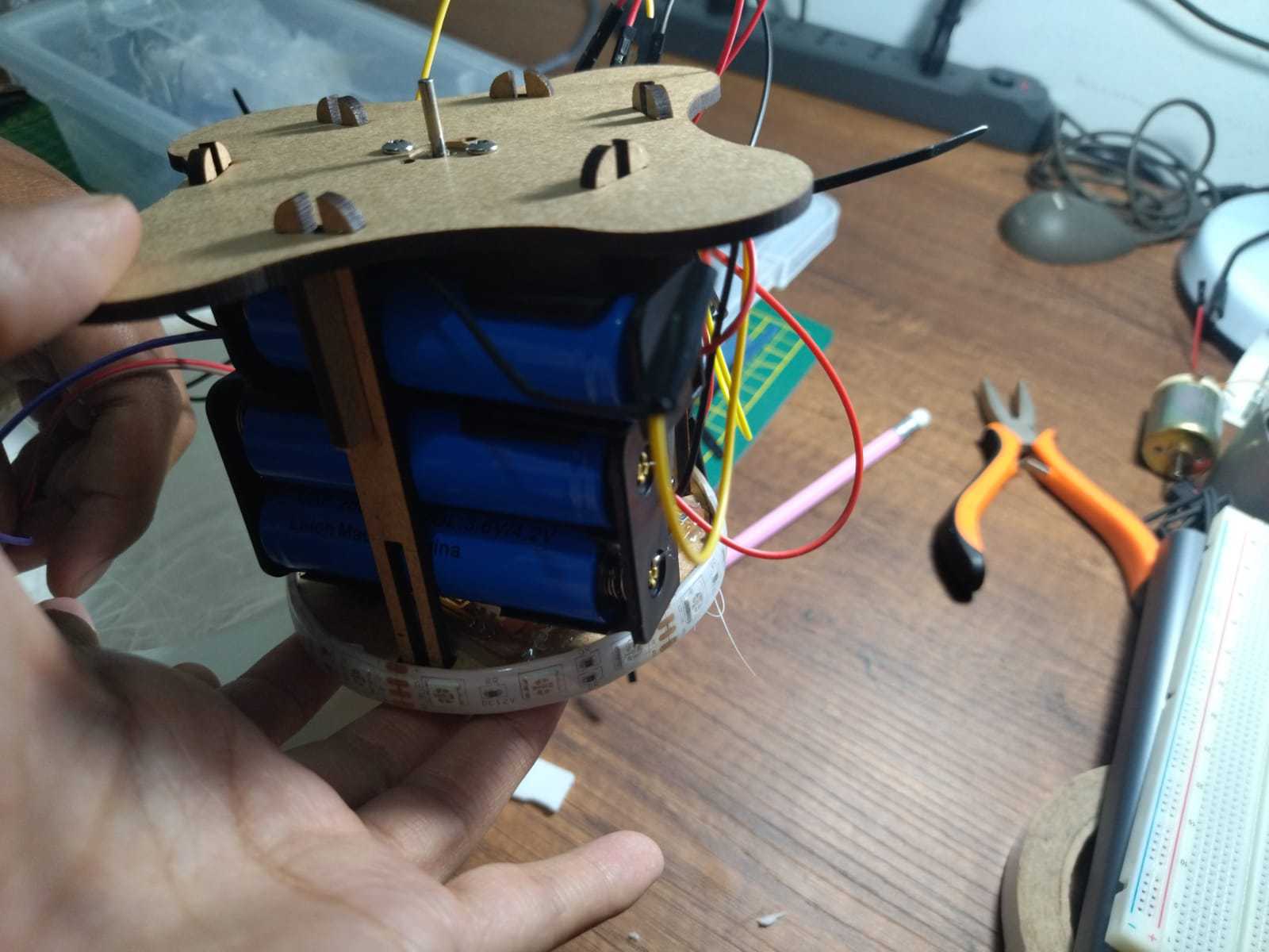
Board location
Testing of assembled parts
Last details
Now that everything is working, I make some important adjustments for Quentino, first of all, I made the test with characters in order to visualize the effect of the zootrope, I placed these first paper tests before moving on to laser cutting.
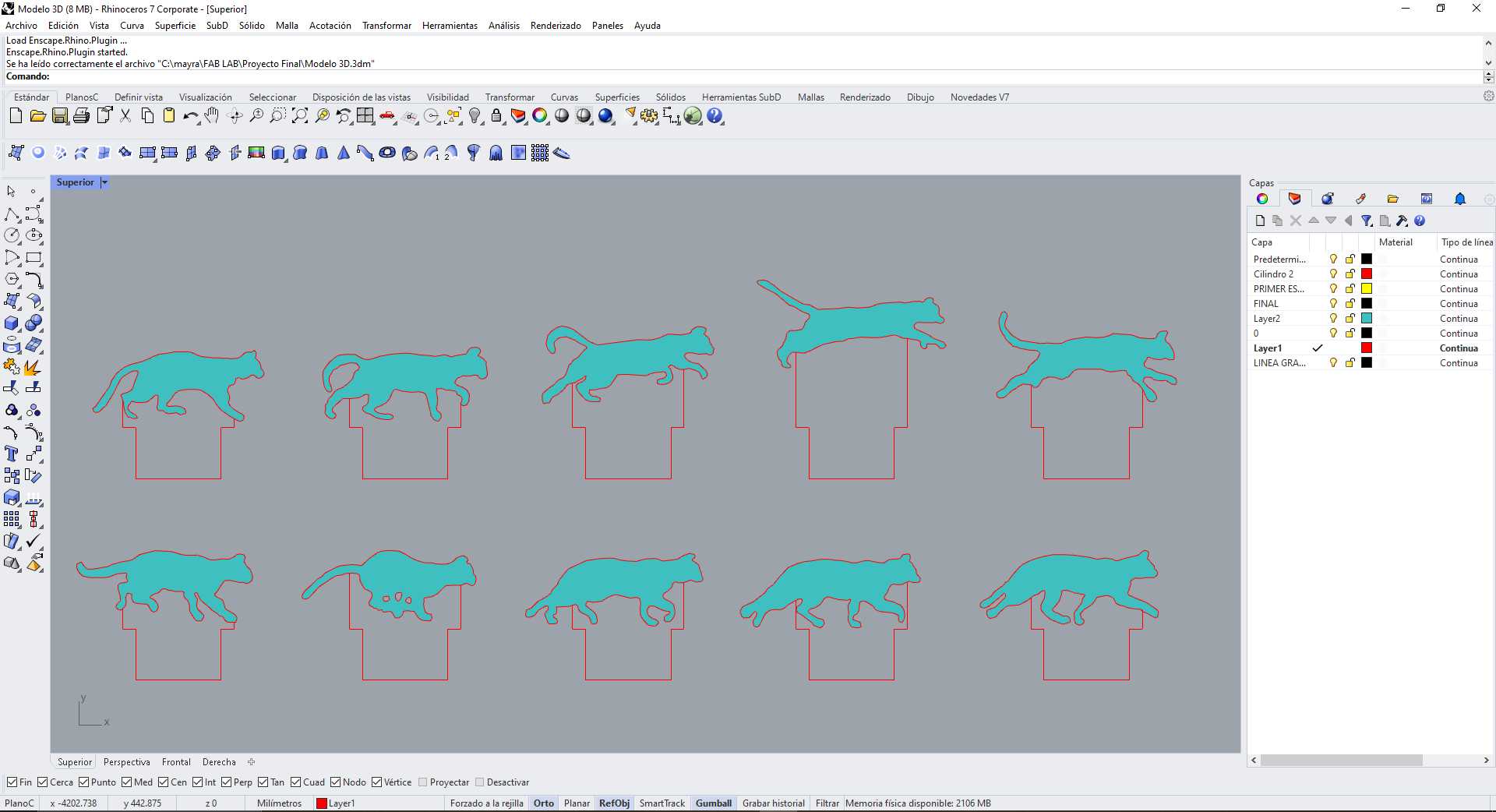
Rhinoceros
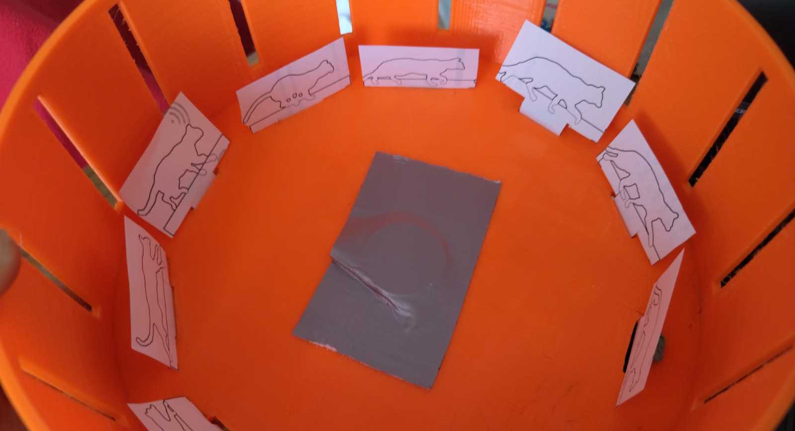
Paper
Testing with a feline
As part of the process, I realized that the vertical characters could be better appreciated, so I decided to try another one that made reference to a jumping human. Here I share the test.
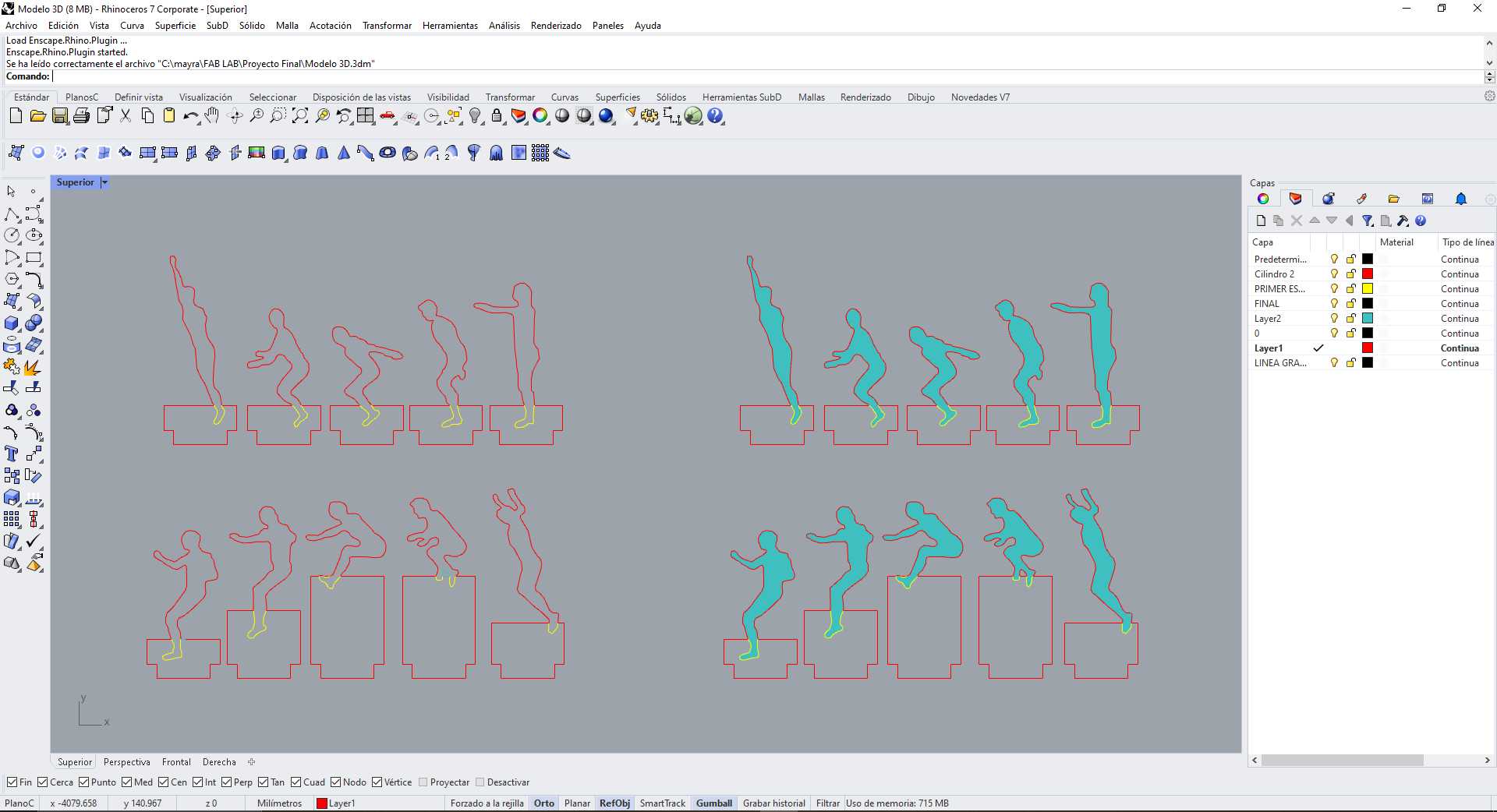
Rhinoceros
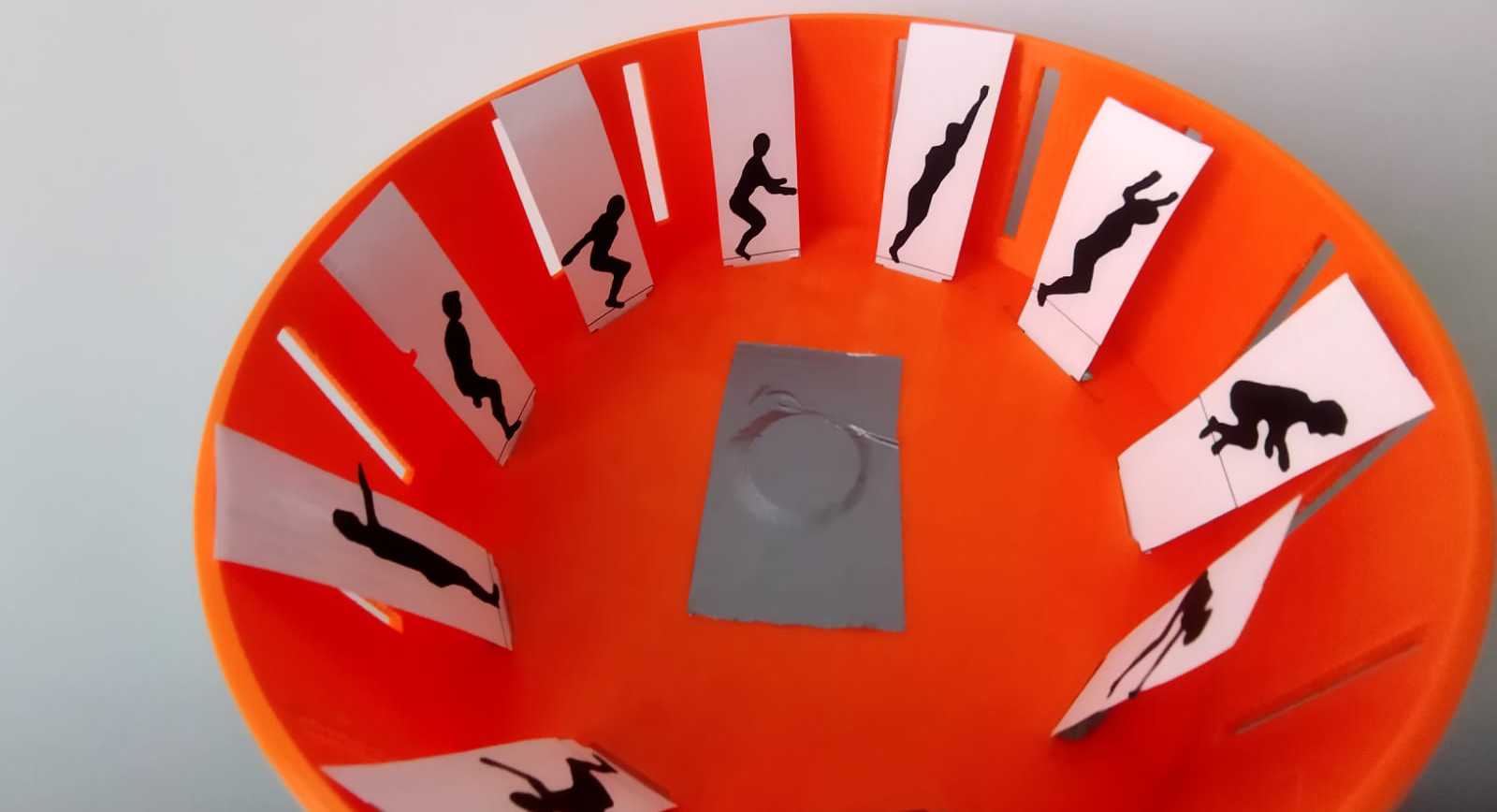
Paper
Testing with a human
After making the tests on paper I made the laser cut of transparent acrylic with black vinyl, this to be able to visualize the effect of the light at the bottom and to highlight the character I wanted to use.
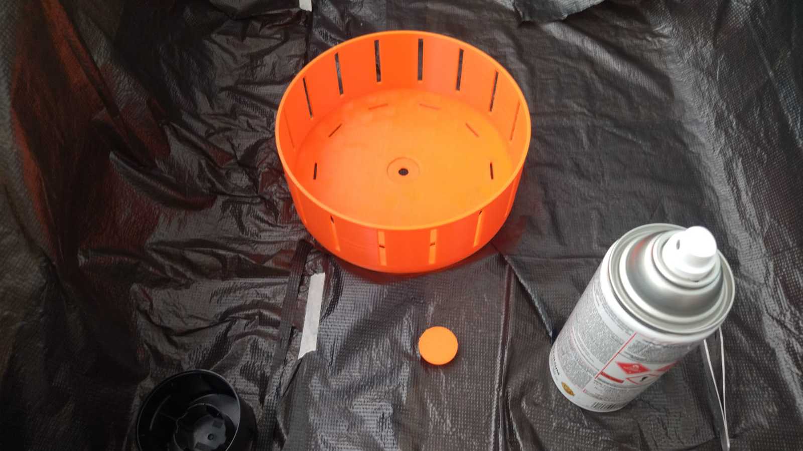
Black spray
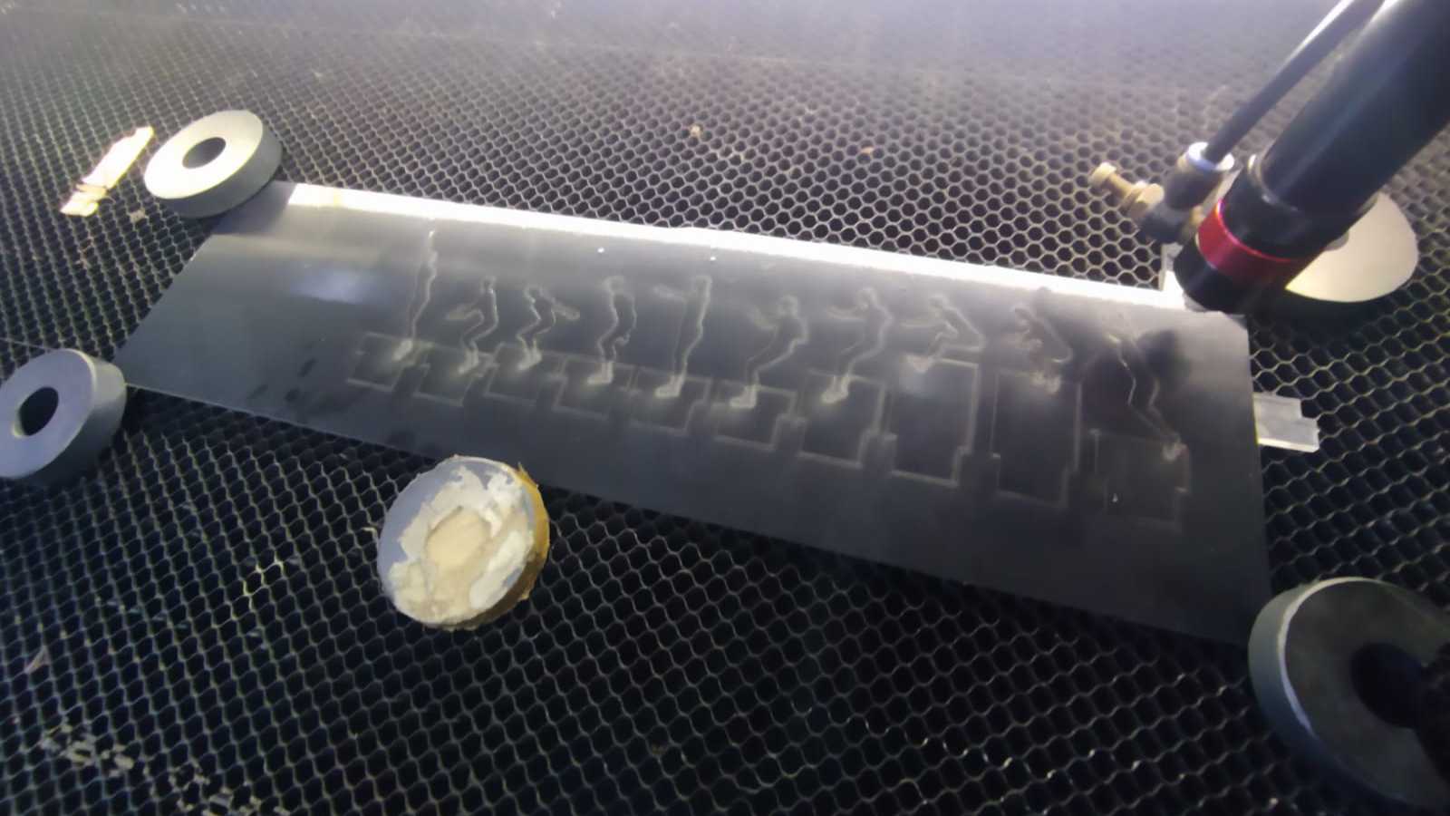
Laser and vinyl cutting
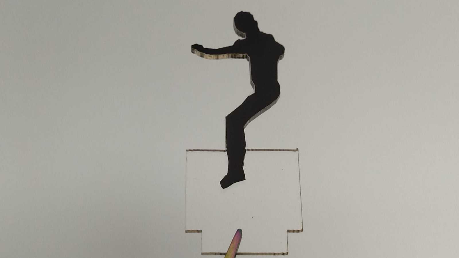
Character

White background
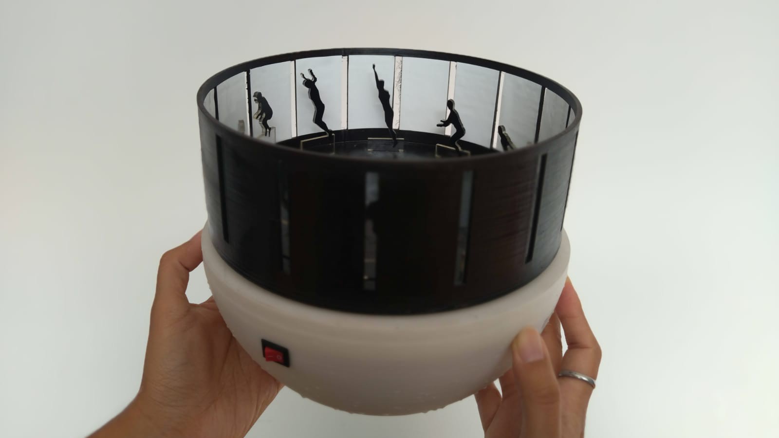

Quentino off

Quentino on

Quentino running

Quentino logo

Download the files here
Quentino_Arduino_IDE
Quentino_3D
