Fourth week

Fourth
class

This February 17 was the Electronics production class and I found it interesting that I didn't understand even half of the session. I have no experience in anything electronic and this is the first time I see board topics so I'm sure this week will be a real adventure. On Wednesday I decided to volunteer for the second time to expose how difficult it was for our team to solve the task with the broken machine, I think when you have challenges like this we learn more as we test ourselves with problem solving.

Anyway I know it will be fun and I will keep on working hard to get the best results, I thank once again to the Barcelona team for all the support from afar and of course to my heart team Fab Lab Peru. πŸ’“


Second time as a volunteer


My experience

General concepts


- Voltage: Electrical voltage or potential difference (also called voltage) is a physical quantity that quantifies the difference in electrical potential between two points. It can also be defined as the work per unit charge exerted by the electric field on a charged particle to move it between two given positions. It can be measured with a voltmeter. Its unit in the International System of Units (SI) is the volt.
- Conductive materials: Conductive materials are those that offer little resistance to the passage of electricity. Electrons can circulate freely through the material because they are weakly bound to the atoms and can therefore conduct electricity. For example: aluminum, bronze, nickel, gold.
- LED: A light-emitting diode or LED (also known as a light-emitting diode) is a light source consisting of a semiconductor material with two terminals.
- PCB: A printed circuit board is a circuit whose components and conductors are contained within a mechanical structure. Conductive features include copper traces, terminals, heat sinks or flat conductors. The mechanical structure is made of insulating laminated material sandwiched between layers of conductive material. The overall structure is plated and covered with a non-conductive solder mask and a printing screen for electronic component legend location.
- Electronics components: Electronic components are the devices that make up the circuits that make appliances that we use in our day-to-day life work, such as cell phones, televisions or hair dryers. They come encapsulated in ceramic, metal or plastic. They usually have two or more metal terminals or pins.
- Resistors: These are the components in charge of "opposing" the flow of electric current. They are in charge of slowing down or attenuating it to prevent it from flowing without any control. Their resistance capacity is measured in ohms (Ξ©) and their power, i.e. the amount of electricity they can control without burning out, in watts (W).
- Capacitors: These are found near resistors and can store an electrical charge temporarily. There are many varieties, but the most common are electrolytic and ceramic disc capacitors. Their capacity is measured in microfarads (ΞΌF).
- Diodes: These elements allow electric current to flow in one direction only, as long as the positive voltage is applied to the diode terminal known as the anode and the negative to the terminal called the cathode. If it is done the other way around, the electric current will not pass.
- Transistors: These are one of the most important devices in electronics and have three terminals. Voltage is applied to the base, which controls the current passing through the other two terminals, the collector and the emitter.
- Integrated circuits: This is one of the most special electronic elements as they contain, in themselves, an entire electrical circuit. The most modern electronic devices, such as computers or cell phones, are built from this type of element. Although this represents an advance, it is also true that it makes the reuse of components and their repair more difficult, and makes us more dependent on the technical services of large companies. A fact that is closely related to planned obsolescence.
- Integrated circuits: An anode and a cathode are the two types of terminals in an electronic device. The cathode is the terminal where current leaves an electronic device. The anode is the terminal where current flows into an electronic device. Electrical current is the amount of charge passing a fixed point in a unit of time.
- AVR: AVR is a family of microcontrollers developed since 1996 by Atmel, acquired by Microchip Technology in 2016. These are modified Harvard architecture 8-bit RISC single-chip microcontrollers.
- RISC: RISC-V (pronounced "Risk-Five") is a free hardware instruction set architecture (ISA) based on a RISC (reduced instruction set) design.

(Source: Wikipedia.com)

First steps


To understand this assignment
- The first step I had to take, since I am not familiar with these electronics issues, was to do a lot of research. It is important to know the why of the processes in order to understand how to develop what we want to have as a result. Thanks to many tutorials and interaction with the equipment I was able to experience many things before moving on to theory. My recommendation is that for those who are as proactive as me and don't like the theoretical part, look for tutorials to make DIY models and test them. πŸ‘

- Well, the first way to investigate was to open some things at home that had some logic of using boards and LEDs. I had never done it before but thanks to this I could see and touch live how is the internal structure of objects like a smart light bulb, a simple lamp and a mouse.
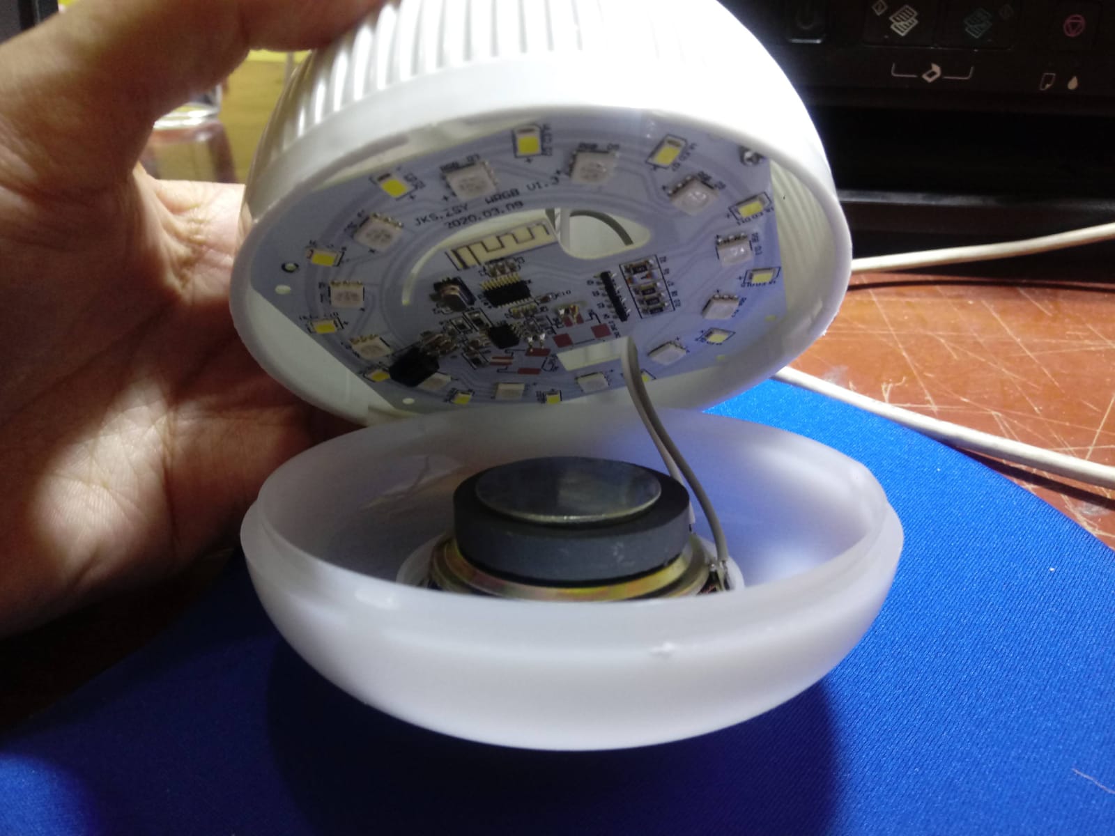


Smart focus
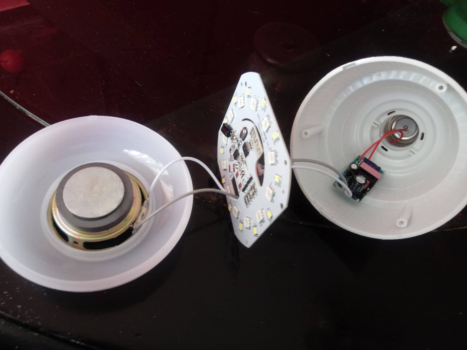


Smart focus
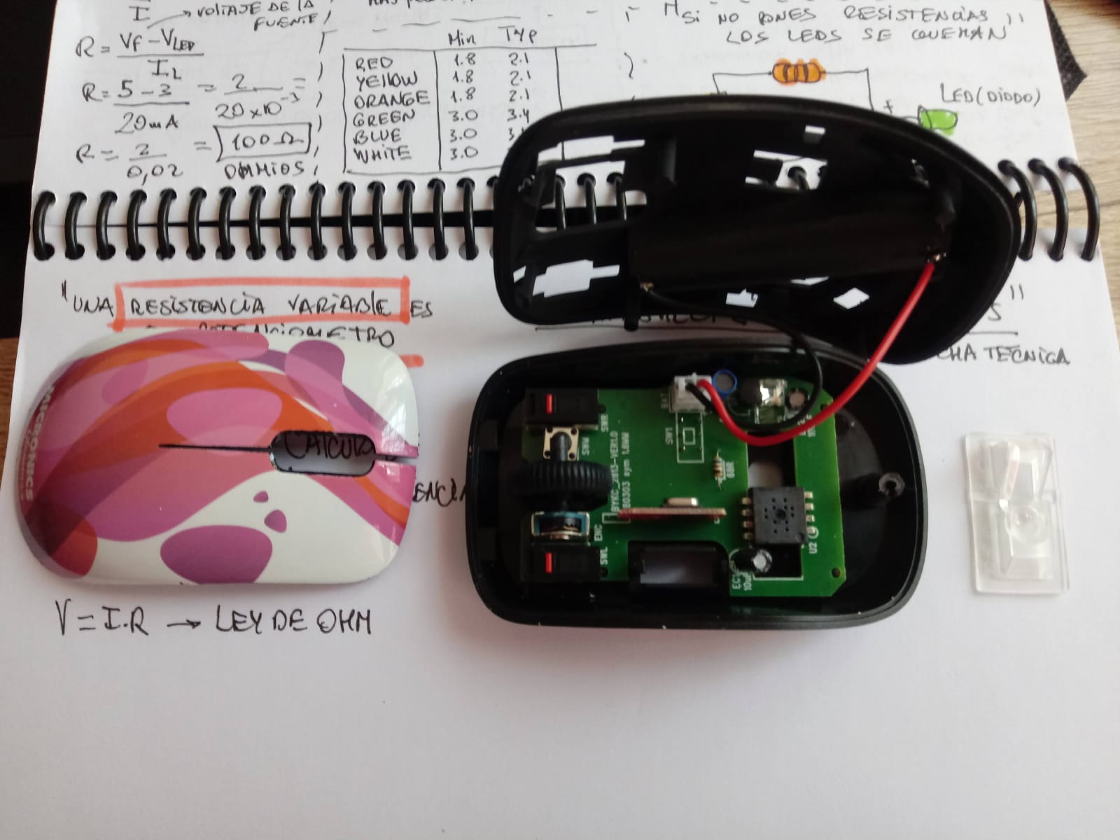
- I found it very interesting to see the circuits and not understand anything, 😒 so to familiarize myself I searched the internet for some similar systems and tried to see the similarities.


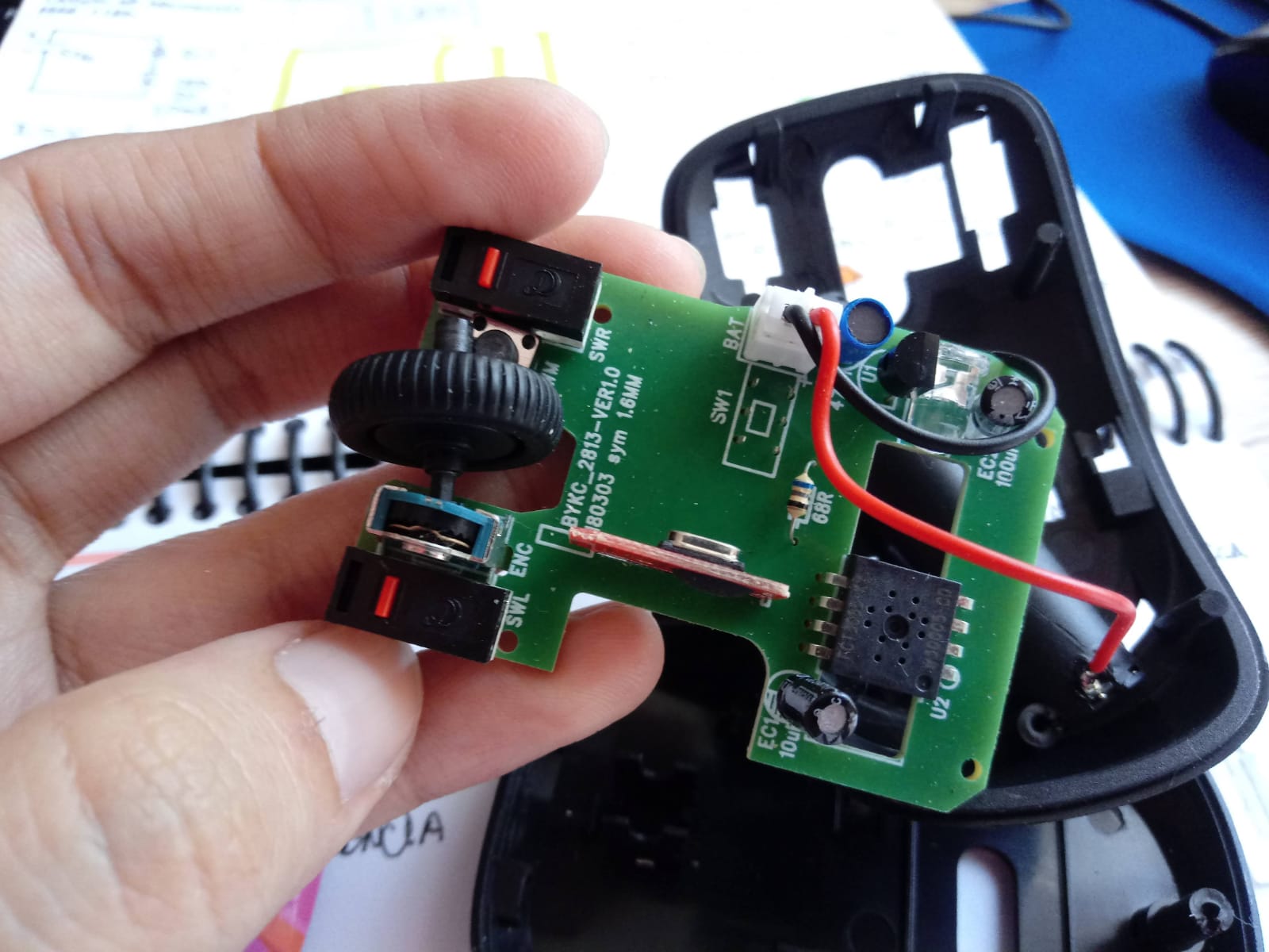
Disassembled mouse


Disassembled mouse
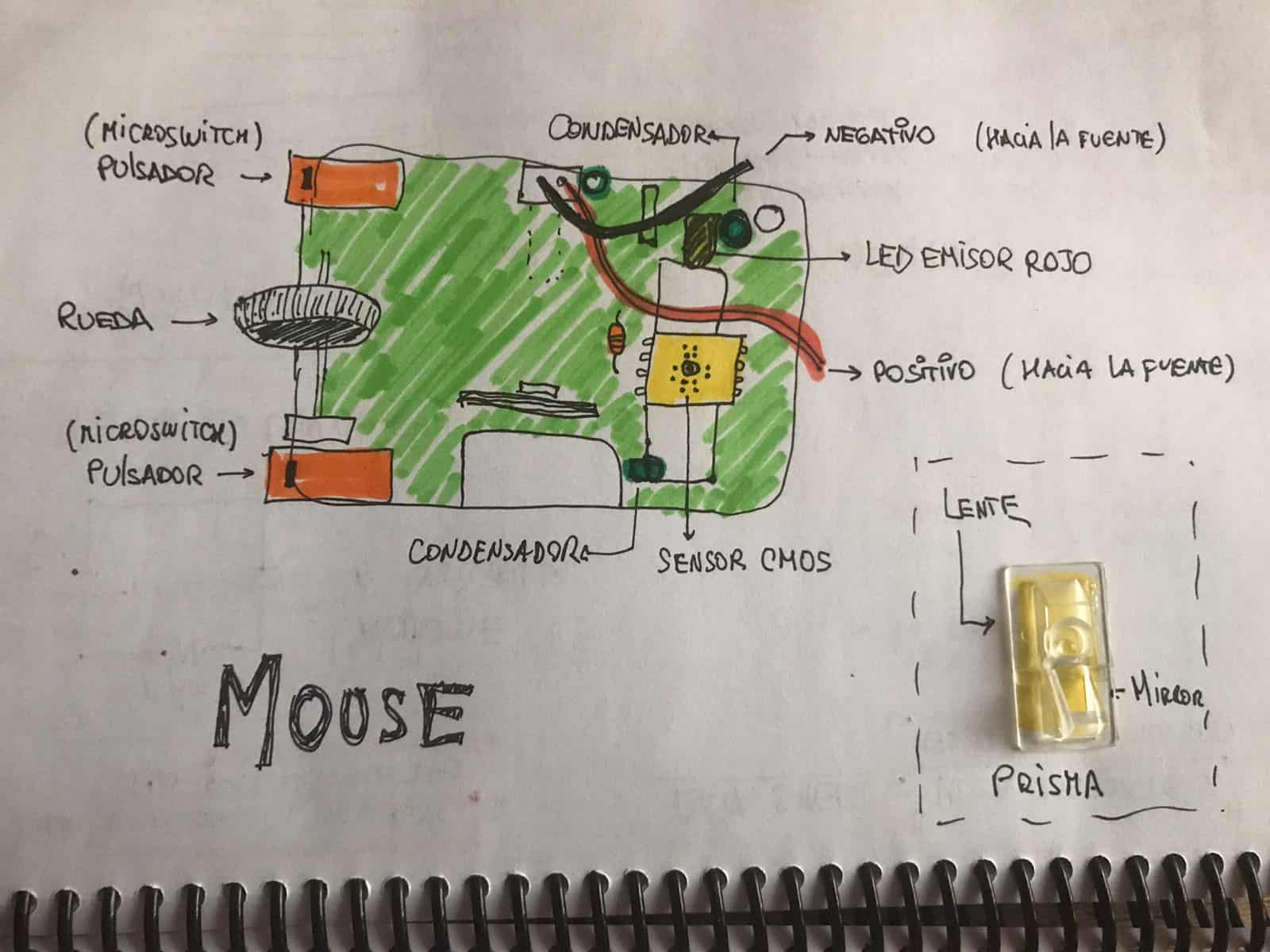

- Thanks to my broken mouse I could take some time to open it and explore it internally before taking it to the trash, now that I know better the electronic components and I know that they can be recycled I will not throw anything away as I was always doing, after having observed it I tried to identify all the possible components. Here I show a graphic I made. πŸ’ͺ


My first graphic


- This exercise helped me to know what I had to understand first, when I saw some leds on the boards it occurred to me to look for how to turn on a led since I had never done it, this gave me very good results since I could understand some concepts like resistance, led, voltage, etc. To be able to build a board and understand its components I investigated in many ways the sequences and connections, this method can help a lot to people like me who are not engineers or knowledgeable about the electronics part.
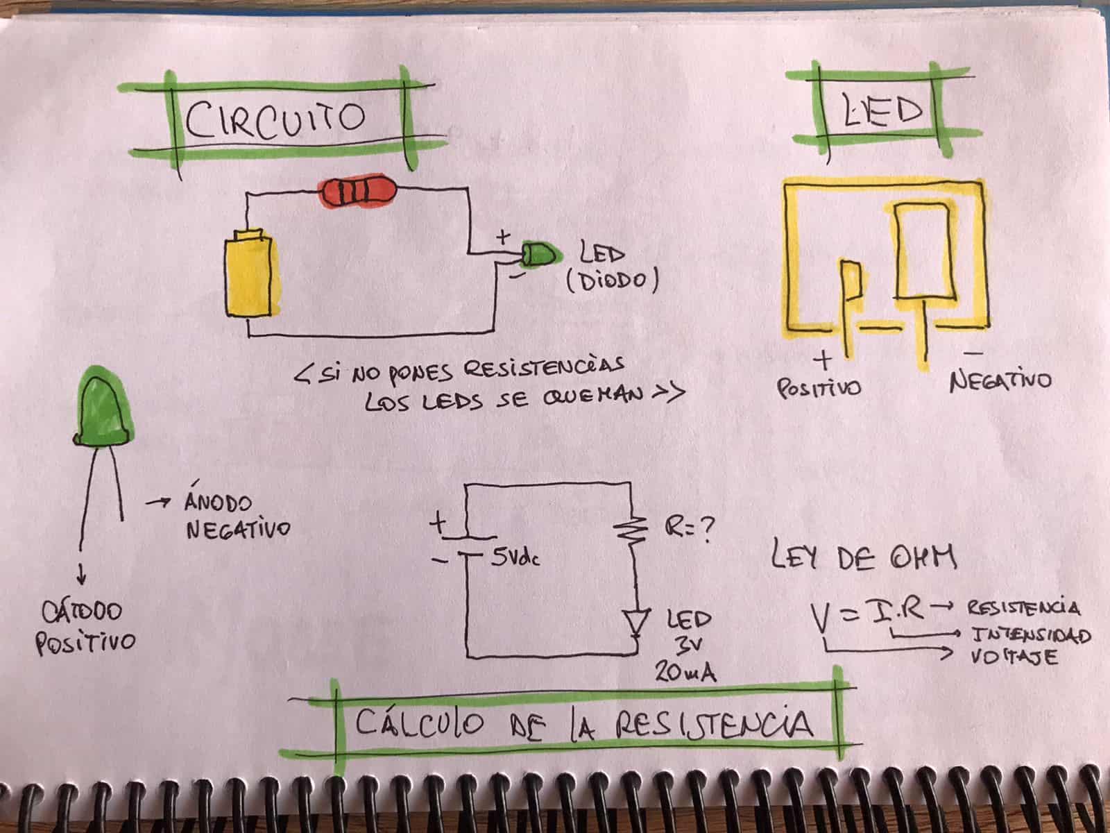


After understanding the conceptual part of the circuits I ventured to perform two experiments, the first was to light an LED with the basics such as an old battery and a resistor. Thanks to the Fab Lab in Lima I was able to get some components and I took them home. The first test was great, for the first time in my life I turned on an LED.
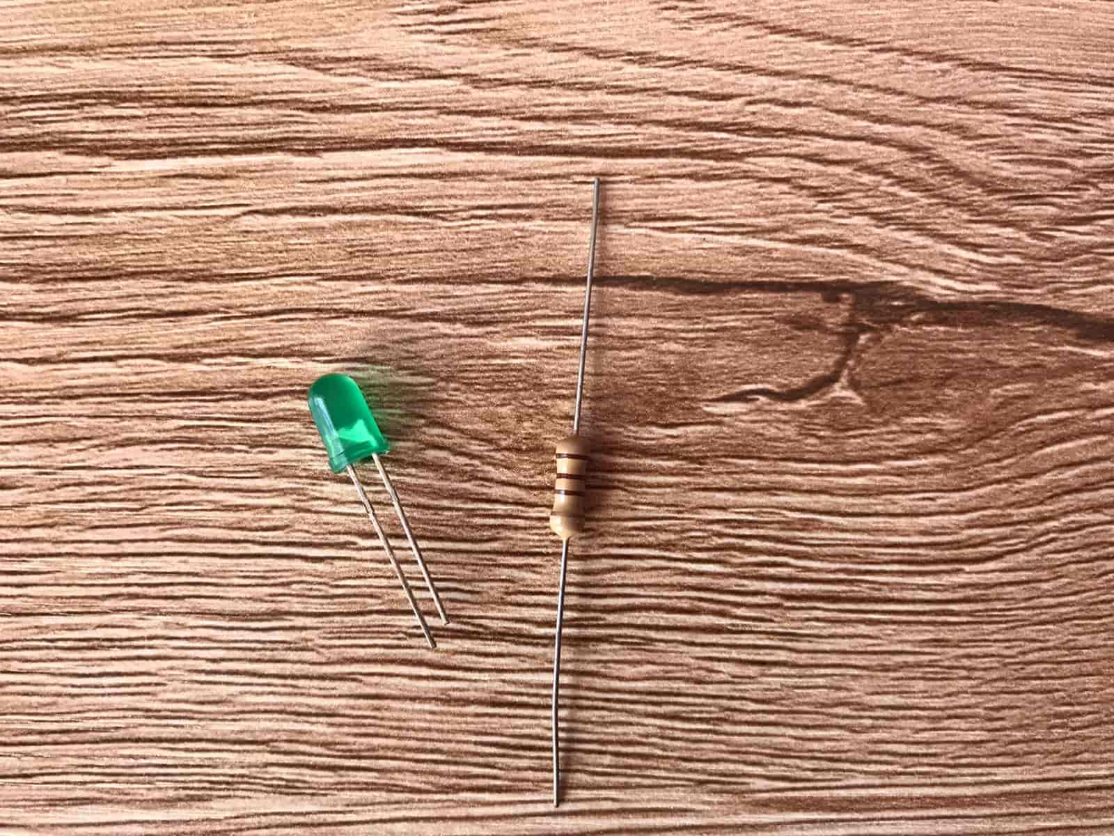


Components LED and Resistor
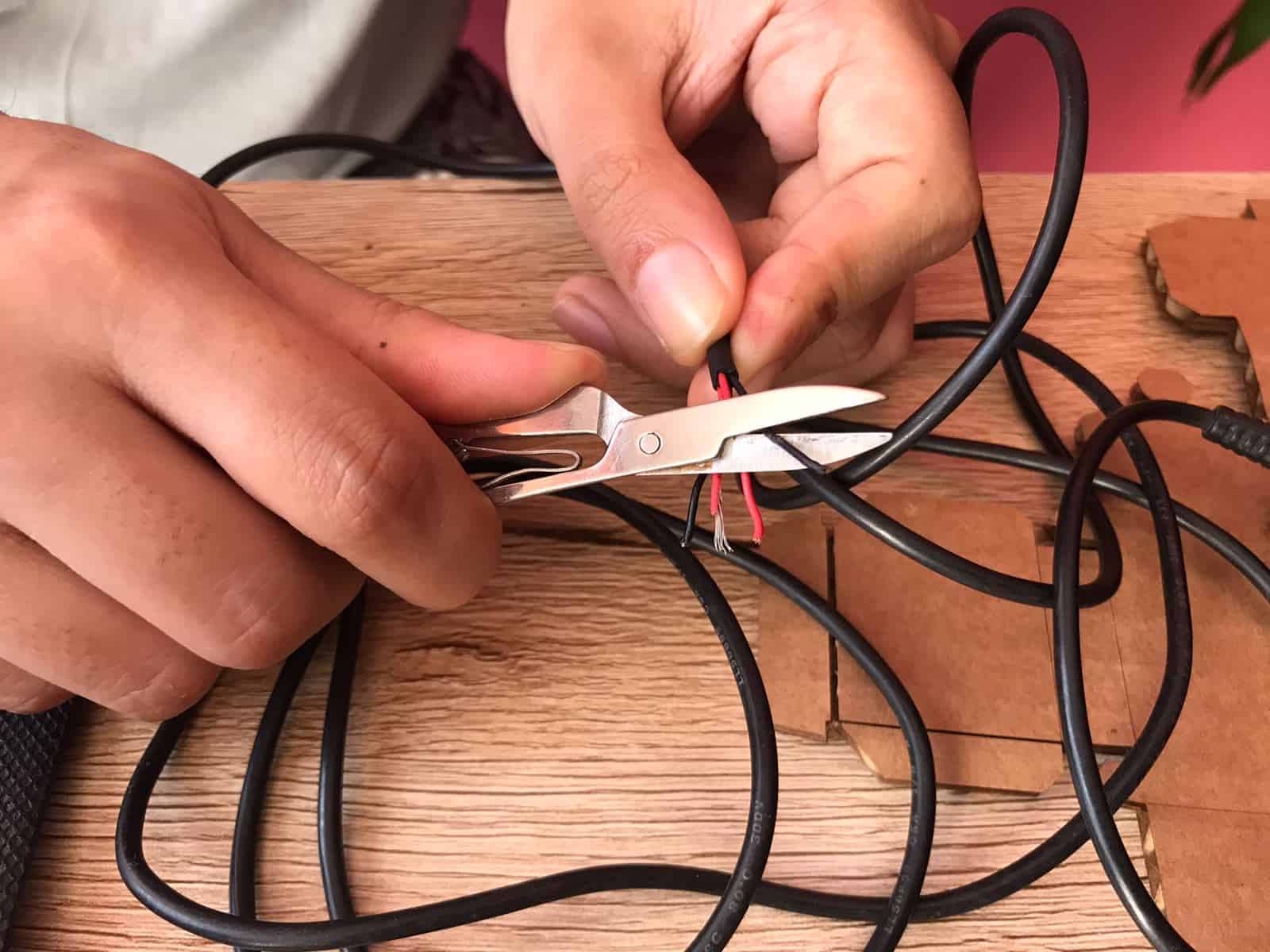


Stripping wires
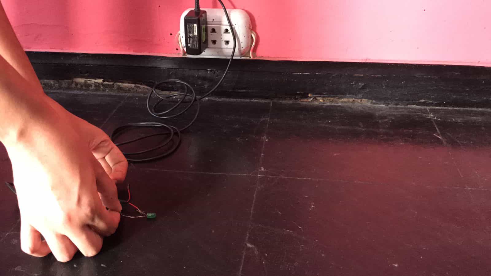


Connecting positive and negative
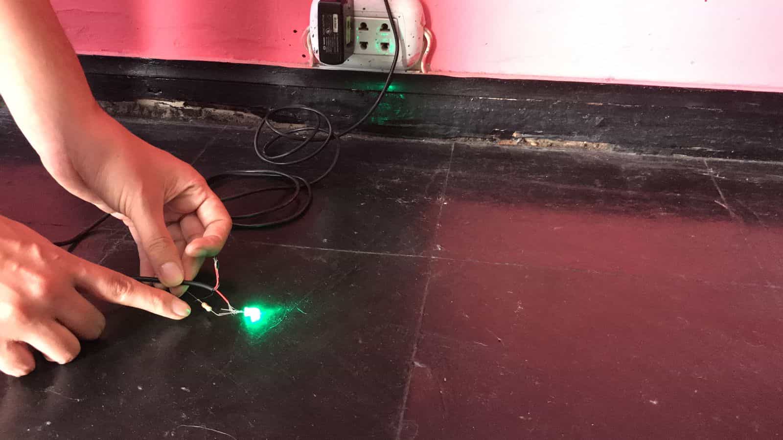


Β‘Turning on the led!


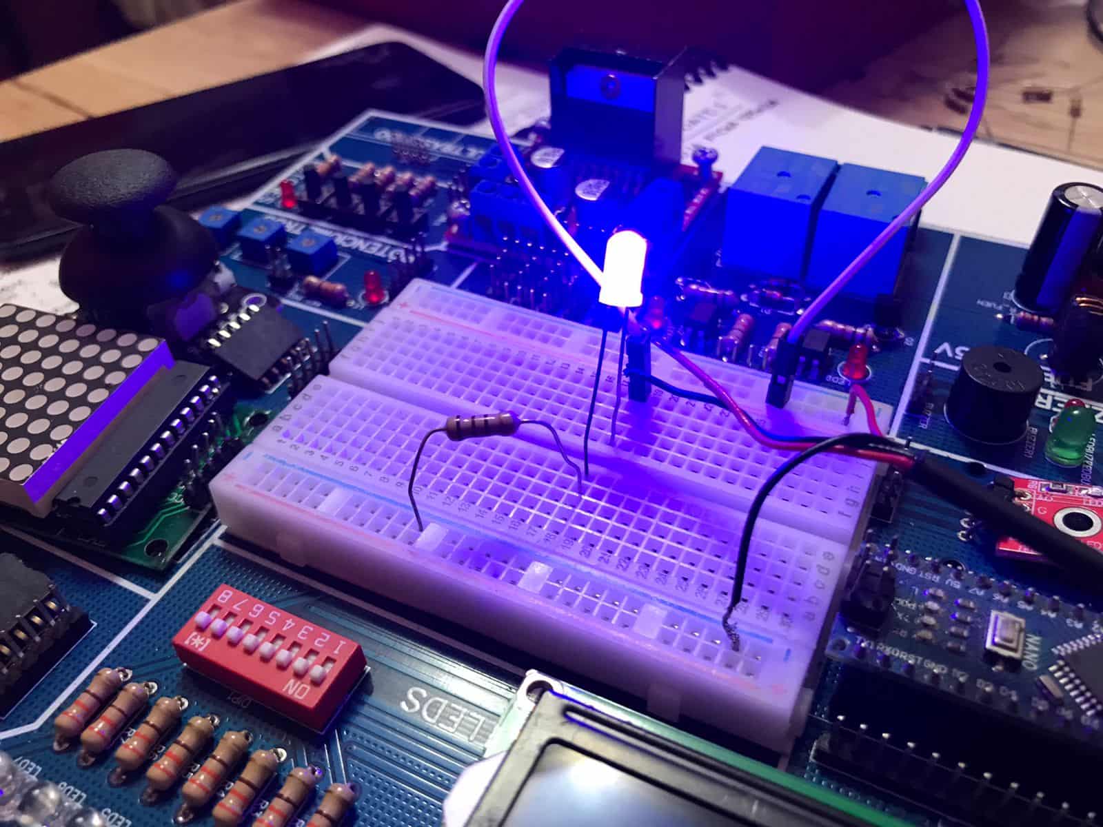
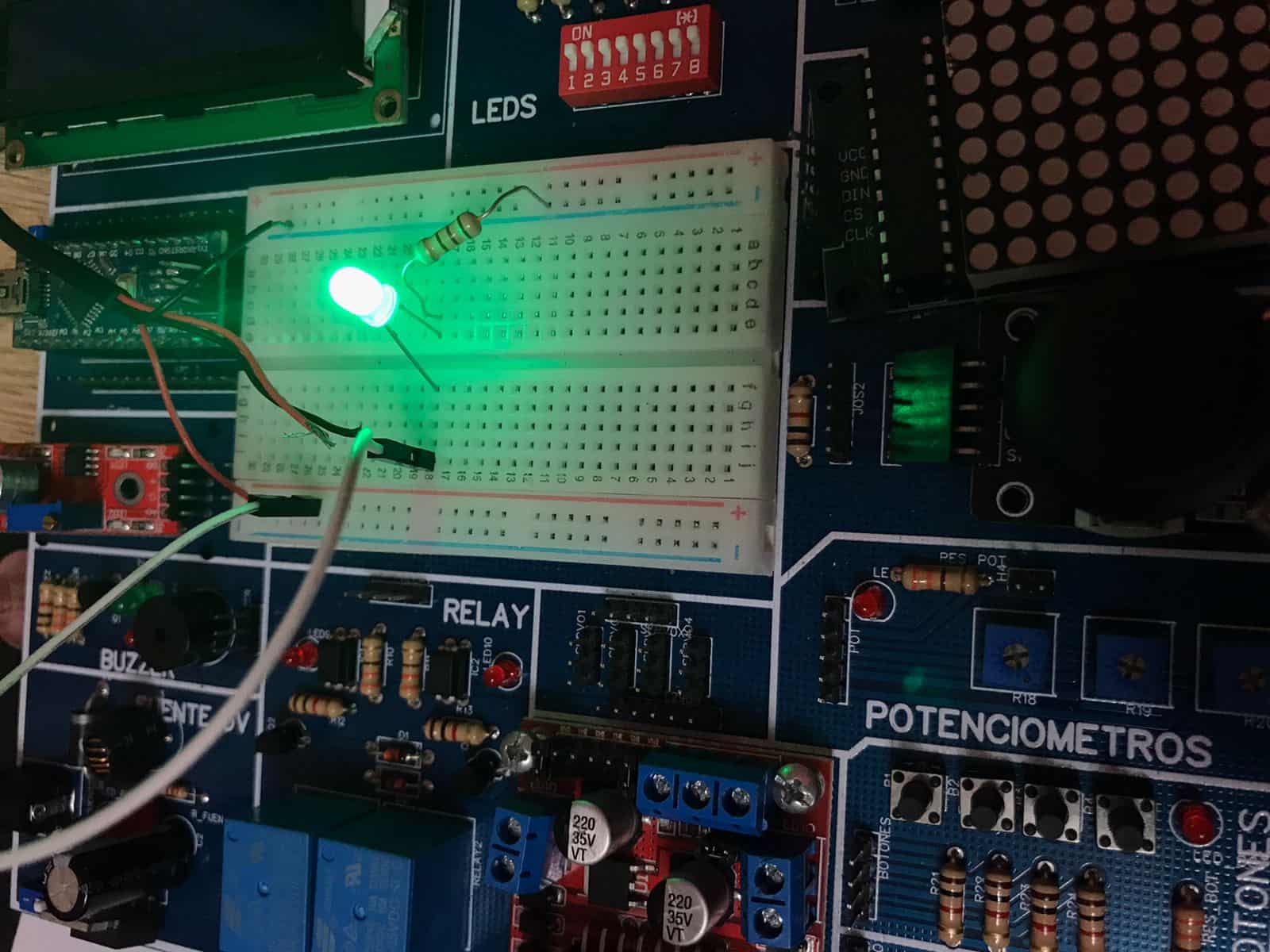
- This event was amazing for me, I really enjoyed solving this little challenge so I continued experimenting. Thanks to Hayashi Mateo, my partner from Fab Lab Peru, I have in my possession an arduino trainer, this allows me to know the basics in the connections on an electronic board. Fabino, the real name of this marvel, has a breadboard so I gave it the first use trying to light an LED but this time with a different logic. 😍


Blue LED


Green LED


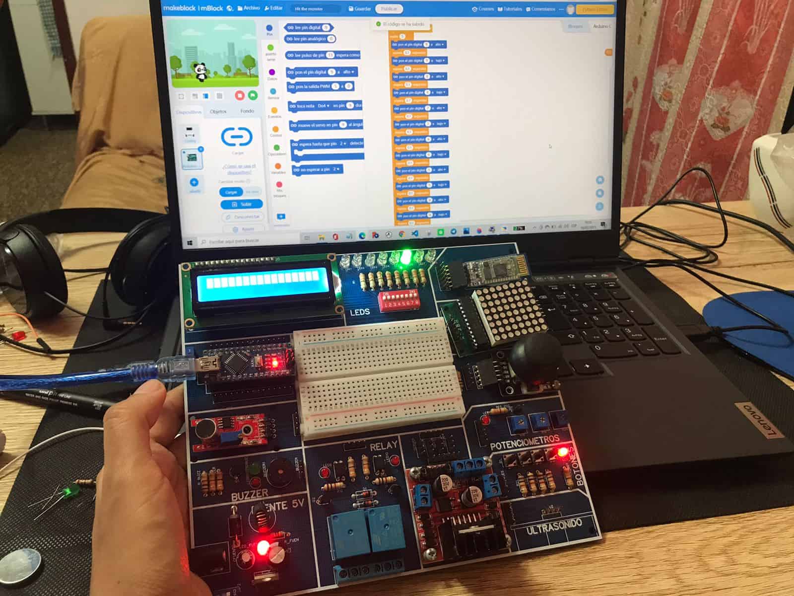
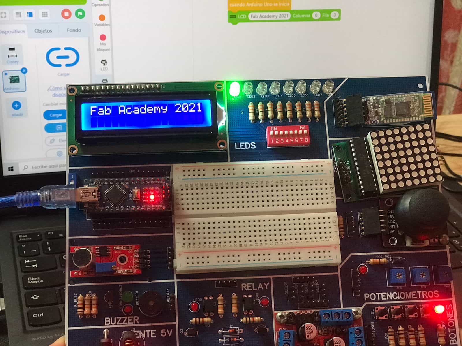
- Fabino is a great trainer! He helped me a lot to understand from the beginning the programming I can give him to turn on leds, to put a text on a LCD, to use sound sensors, motion sensors, etc. This works with a program called Mblock, it is very similar to Scratch, for beginners it is perfect, here I show you some practices.


Programming with blocks


Programming with blocks
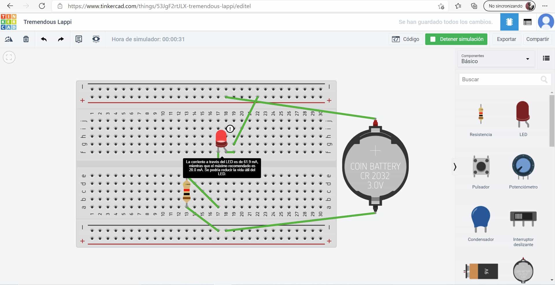

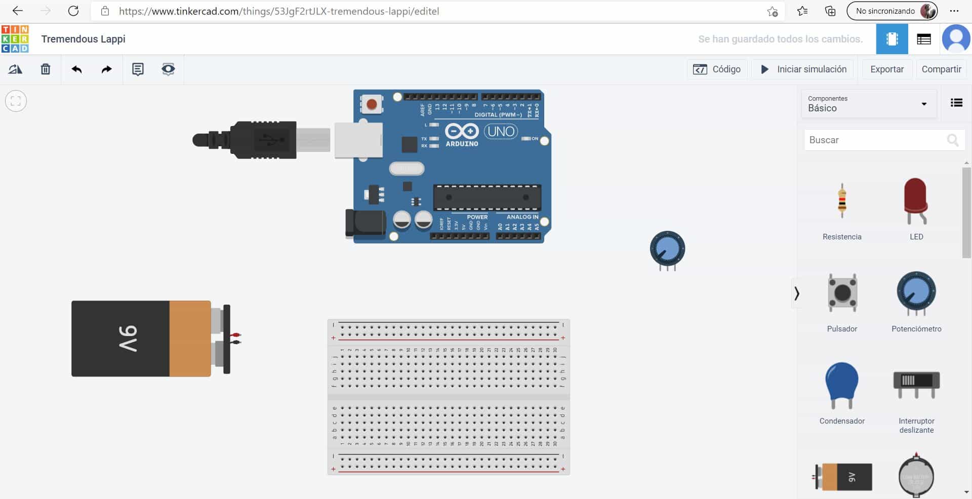
- Another very good idea for beginners in electronics is the free software Tinkercad, this program is completely free and you don't need to download it, it has a space for creating 3D designs but also one where you can learn about electronic circuits. I really liked to start this exploration because virtually you can practice with your components and realize the results before doing it physically, this certainly helps a lot to know the results you can get and improve your proposals. I recommend it! 😍


Exploring with a protoboard


Looking for components
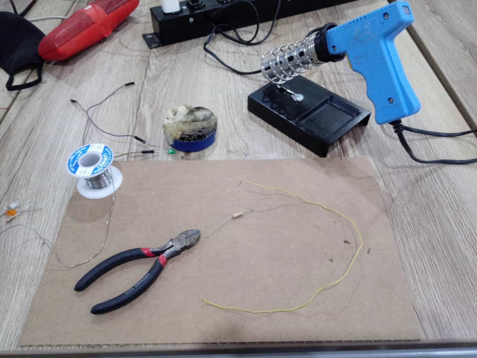

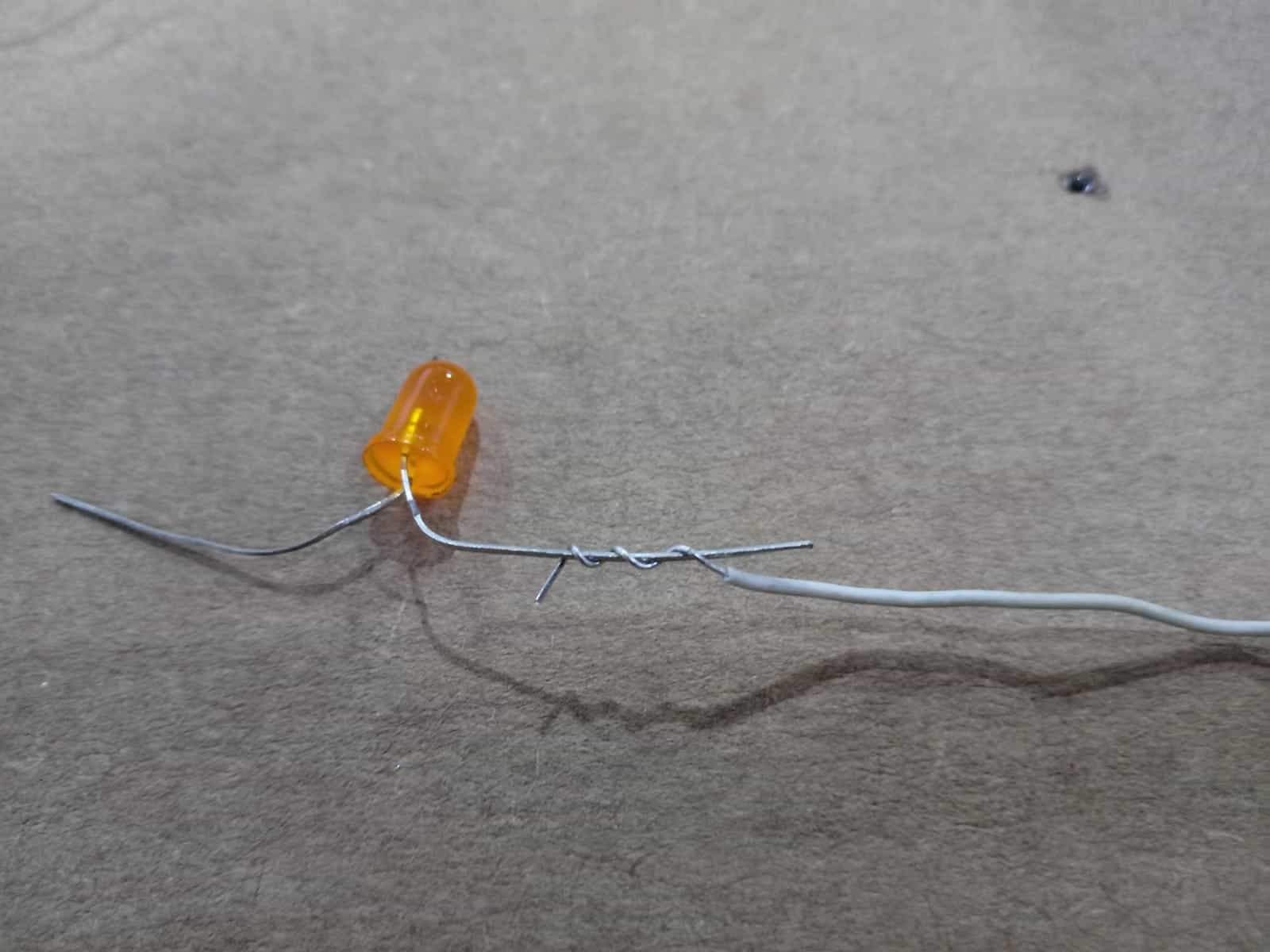
- After these first explorations I ventured to try the practice of welding, it is the first time in my life that I go through this experience. The result was not the best but the emotion was at its peak, thanks to the Fab Academy I am doing things that I had never done before and I really like it.


Instruments


Connection of LED to cable
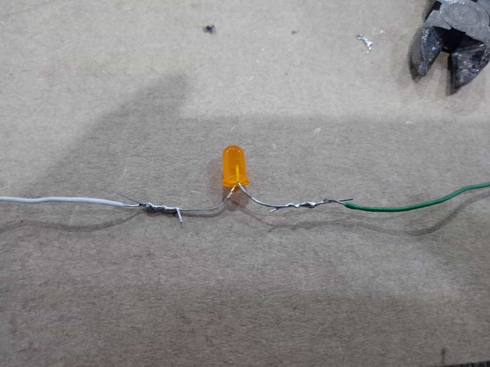


Soldering
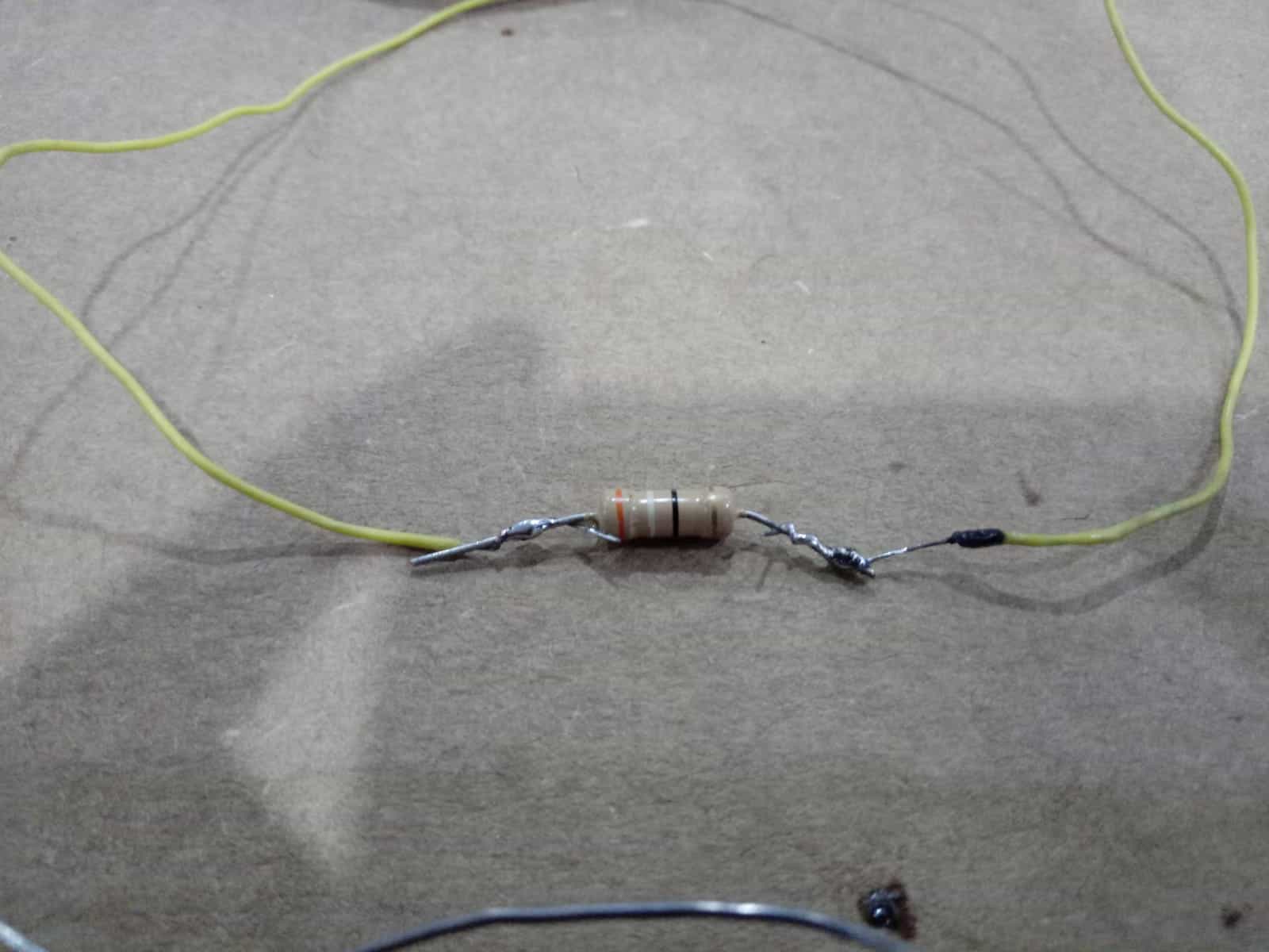


Soldering but with burnt wire


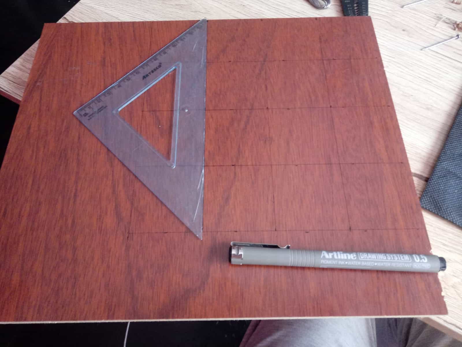
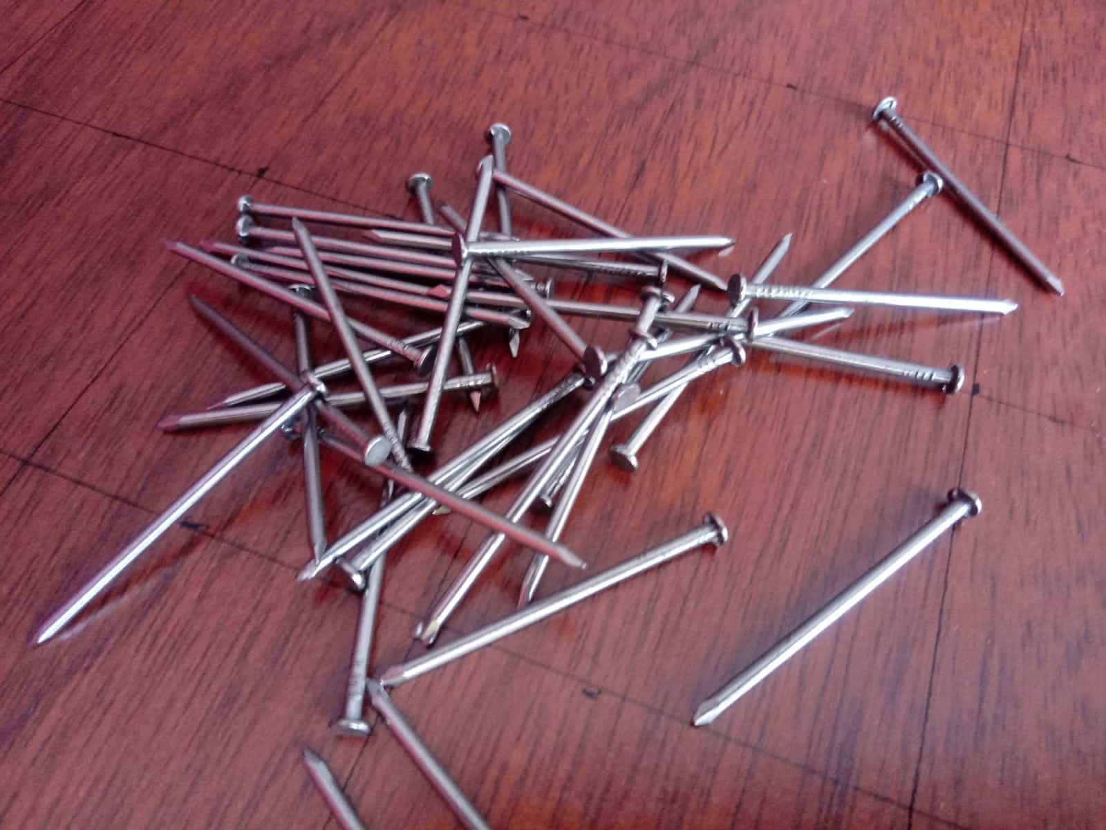
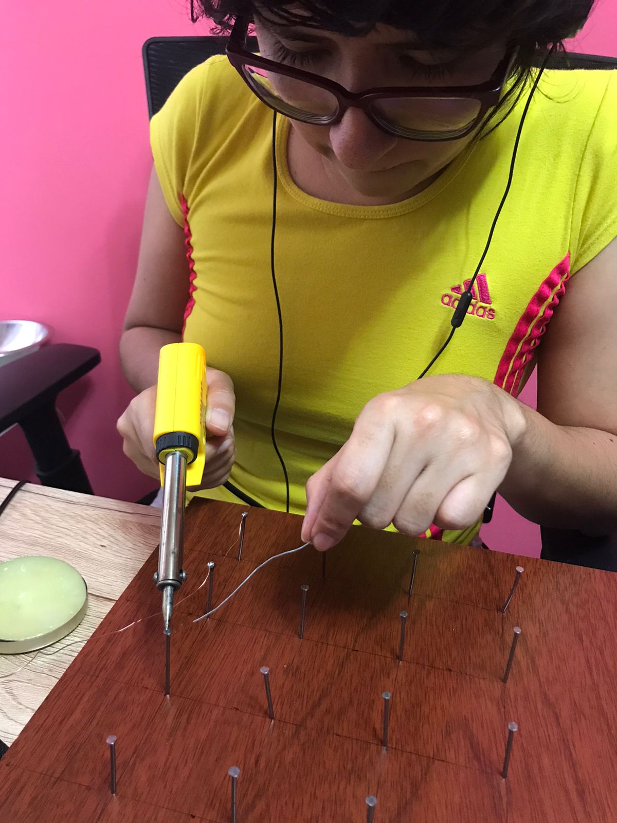
- Definitely with this first attempt I understood that soldering requires a lot of practice, it is important to reach a point of fineness in order not to burn the tin or the components due to the temperature of the soldering iron. Because of this and thanks to my friend Walter from Honduras I did an exercise that he recommended me. I got a melamine board, some nails and a UTP cable, I organized them every 5 centimeters creating a kind of mesh and soldered point to point the heads of the nails with tin. This exercise was very good, it helped me to understand the best way to place the solder and to have better precision. I highly recommend it, Thank you Walter! πŸ₯°


Organized workspace


Keys


Practicing precision
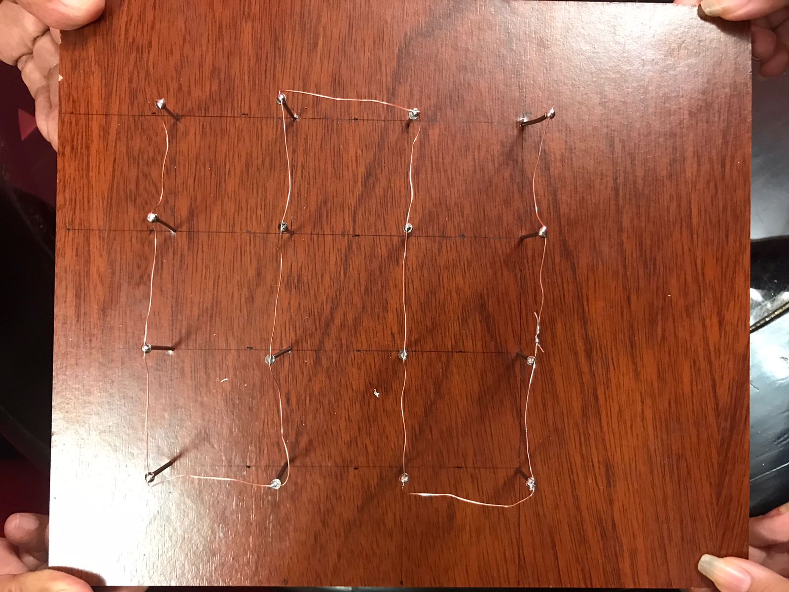


Final result


-Thanks to all these practices I felt more familiar with the concepts and components that we are using, for those who just have knowledge about electronics like me I will tell you that you must have a lot of patience but above all willingness to learn and to solve the challenges that you have in front of you. πŸ’ͺ


10

First Assignment

Grupal Assignment

To start with this assignment the team chose to organize itself with respect to the choice of the plate model to be developed, once chosen as a second step it was necessary to know what tools and components we could count on in our city, although there are possibilities of importing certain objects, it was important to know the time we had to solve it so we made a list with what we needed to recognize the supply points.

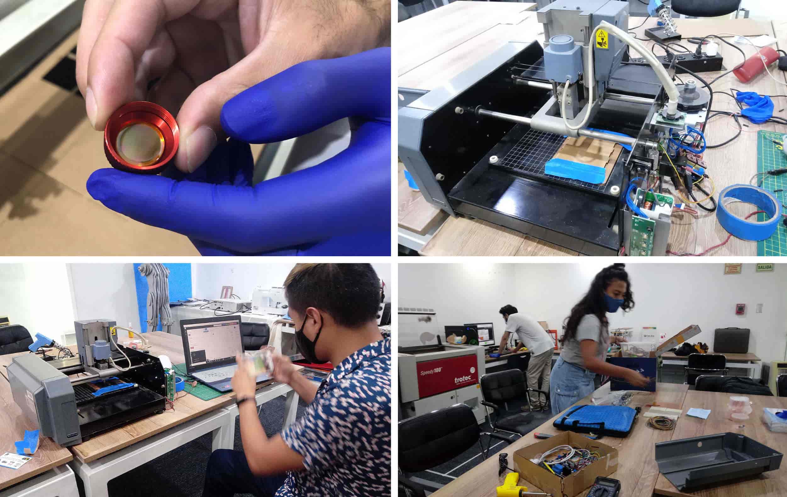
In our Fab Lab we have a milling machine brought from MIT ten years ago, it was not operational for several months so first we had to take care of making it work. In this space I will tell you in detail how was this great adventure, my recommendation is to have a good organization and always work as a team. Let's go! πŸ˜ƒ

Working at Fab Lab and Home

Characterize the design rules
for your PCB production process


This week we went back to the lab and took care of reviewing the tools and components we had, it is advisable to have an inventory before starting to work on any weekly task. In our case we took some time to once again check the laser cutter, install new materials and revive the milling machine that would serve us for this week.

As a result we had a very productive first day as we even had time to do some first tests, in my case I did the first soldering of my life, I must confess that it was fun to try something new but I also realized that I needed a lot of practice, It was a great disaster! πŸ˜ƒ


Super Team Fab Lab PerΓΊ.


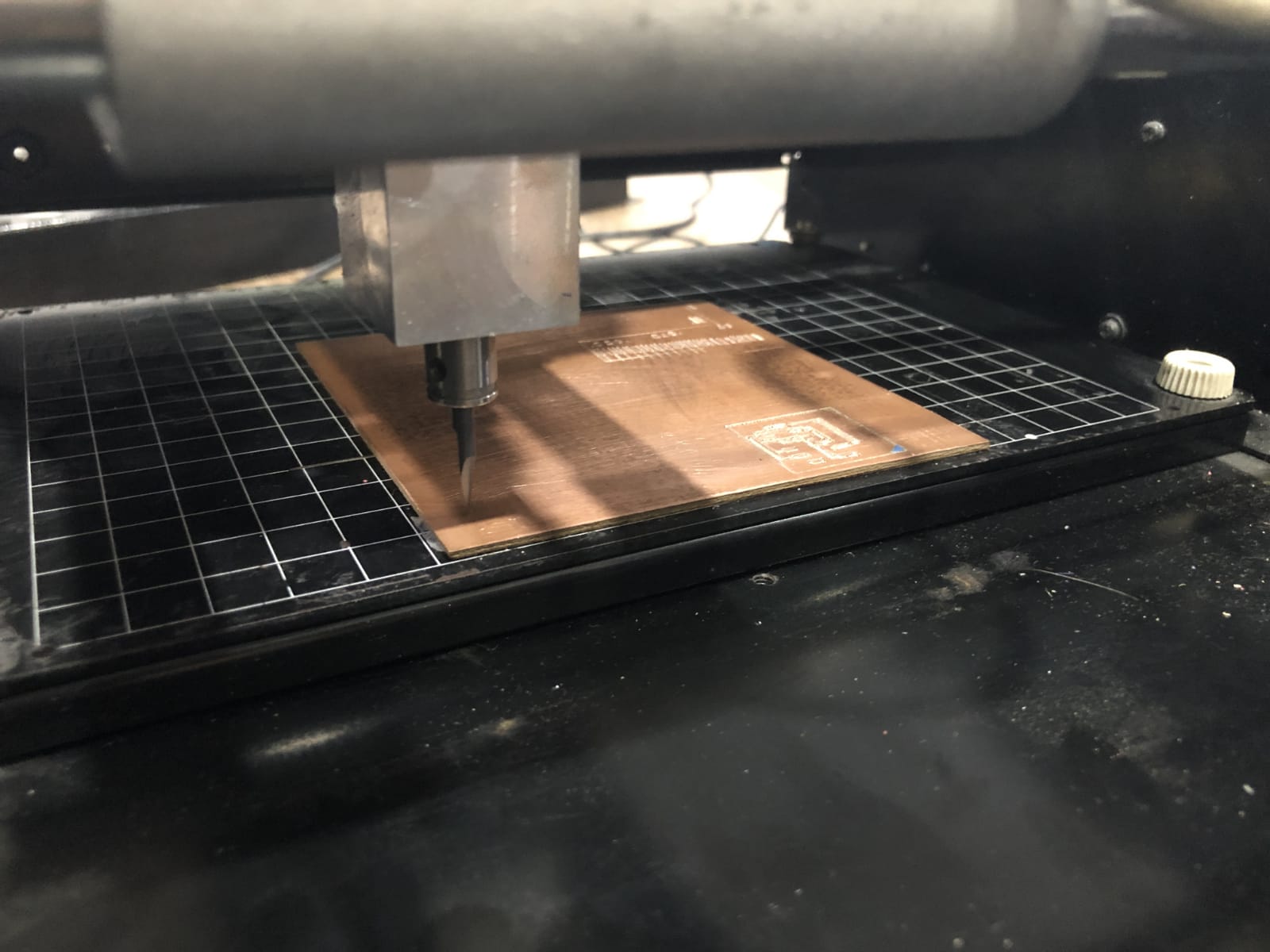
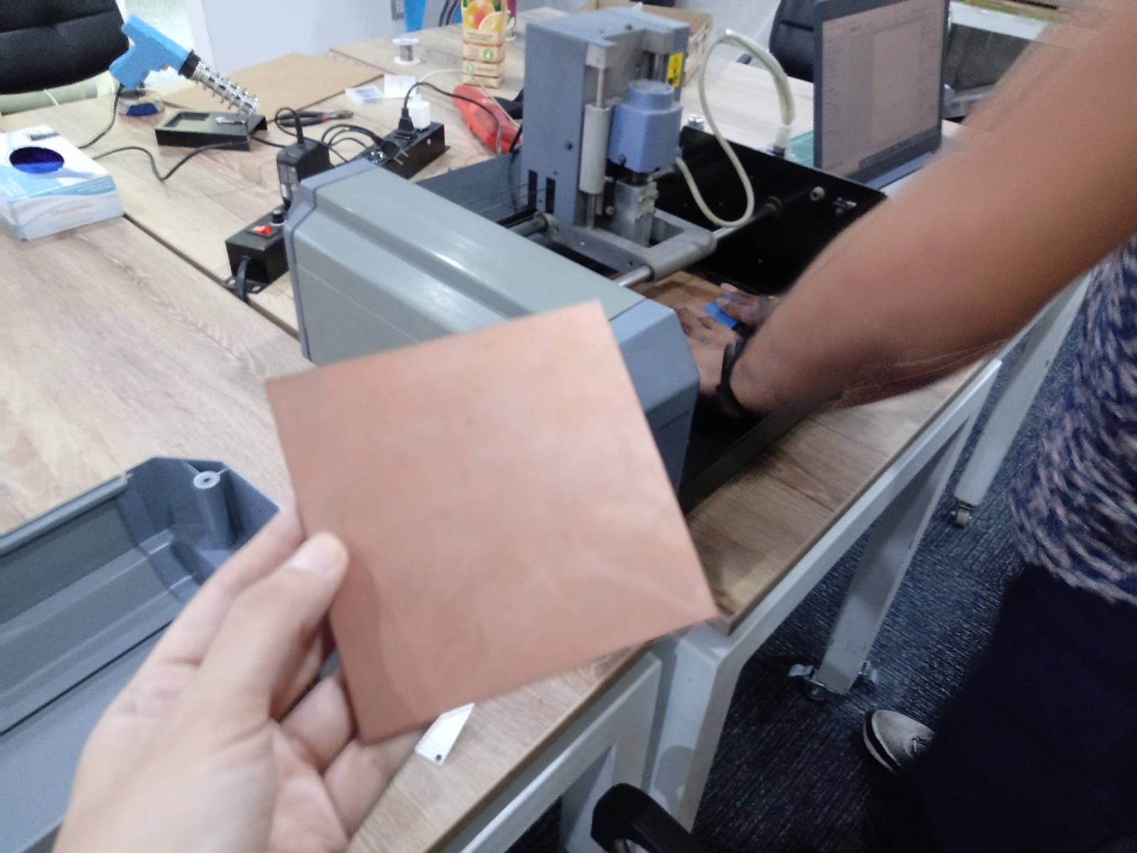
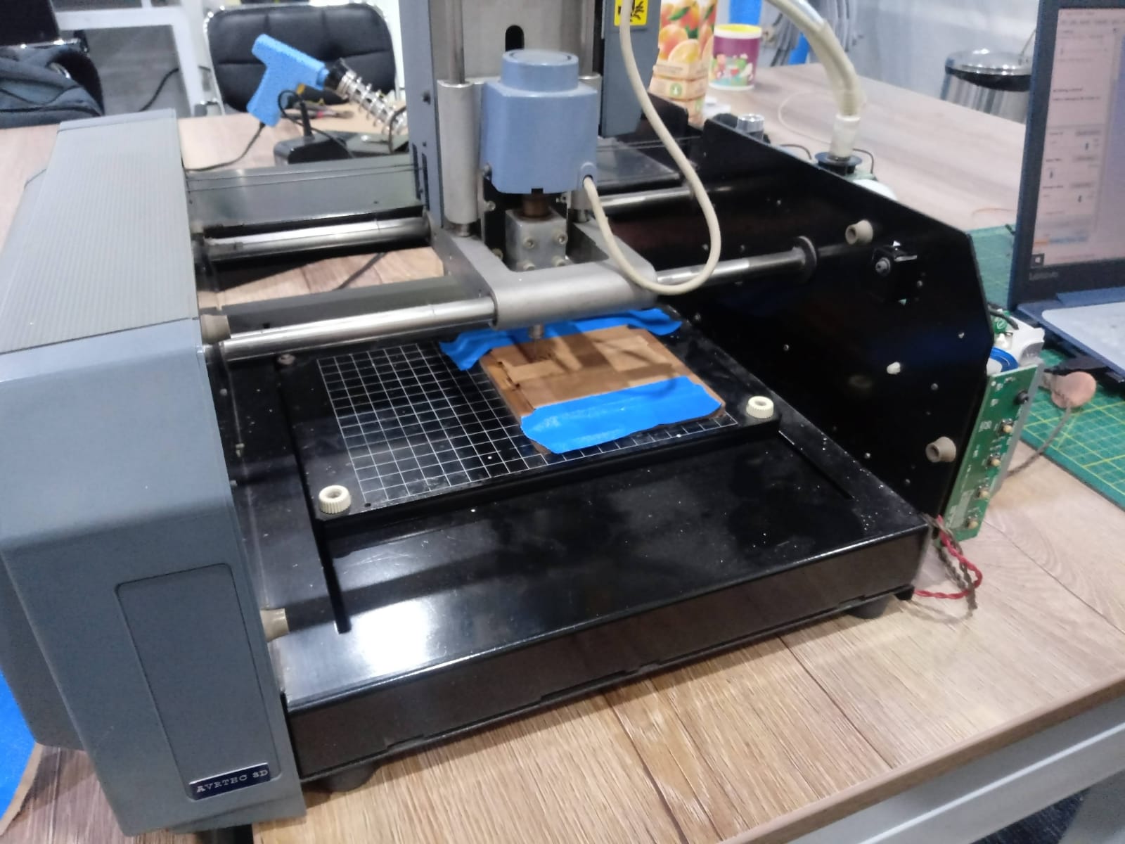
- The laboratory already had access with better organization to make use of the space and machines. As a first test we got together to review the milling machine we have, the model is Roland Modela MDX 20 and it has been revived to complete our work. This machine has been recovered thanks to Hayashi Mateo who was calibrating it to show us the milling process. This day I learned for the first time how the machine operates.


PCB - Baquelita


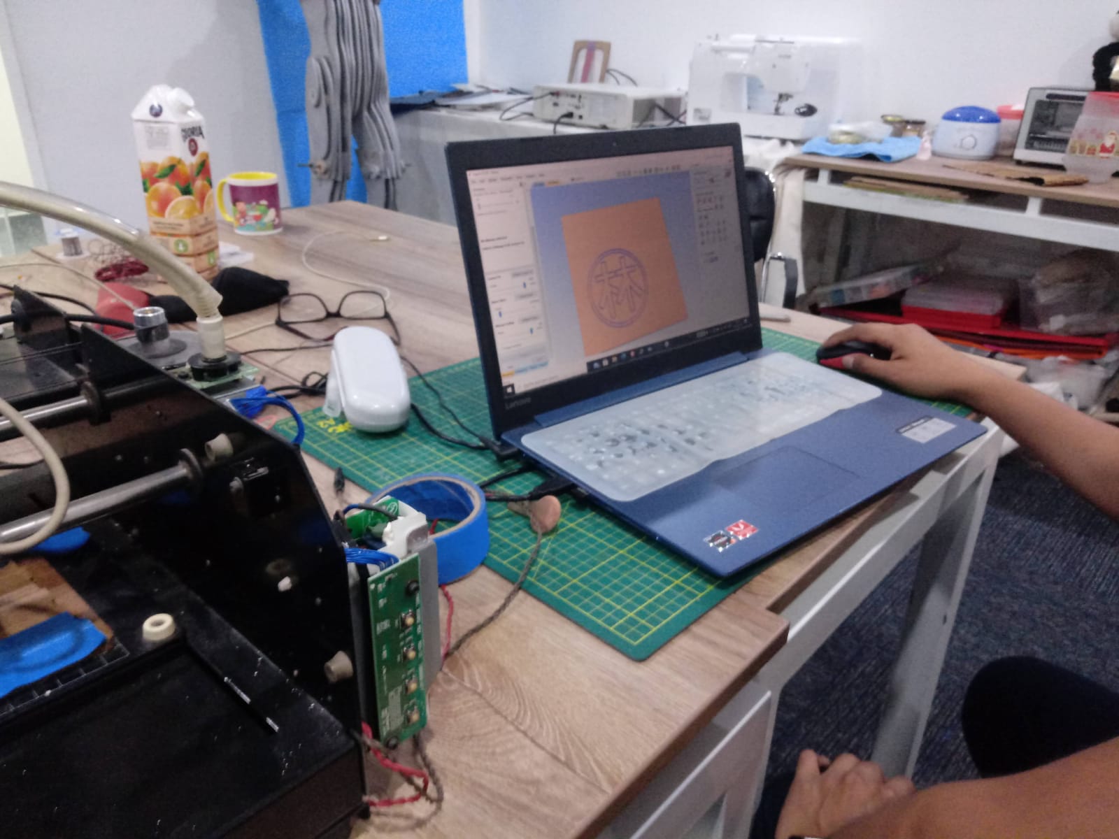
Connecting with the program


Gluing the baquelita


Using the test


- Unfortunately we did not get the components in time and this day we still had to calibrate the milling machine, so Hayashi had to take it home all weekend to make it work properly. Of all the team, he is a mechatronics student and is the most knowledgeable person on the subject, thanks to him I was able to learn a lot of things this week. πŸ₯°

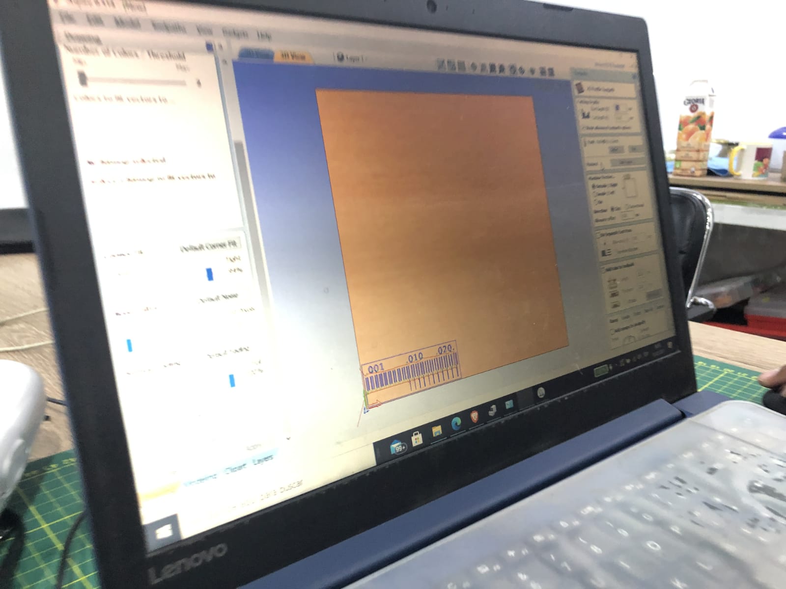
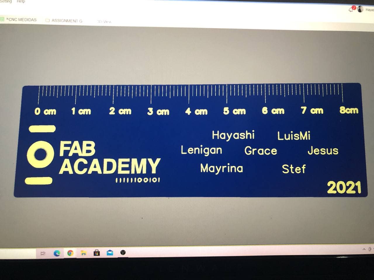
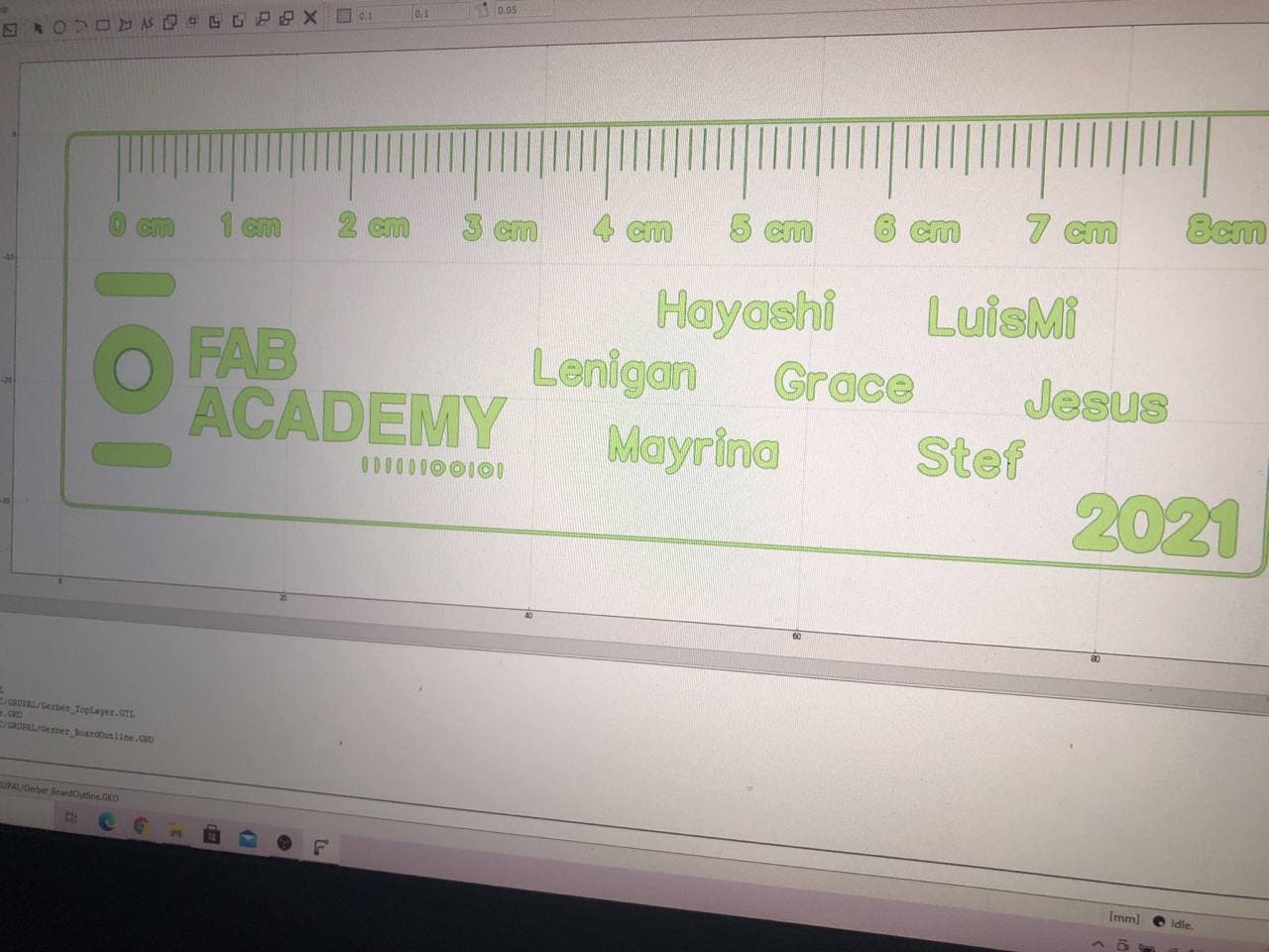
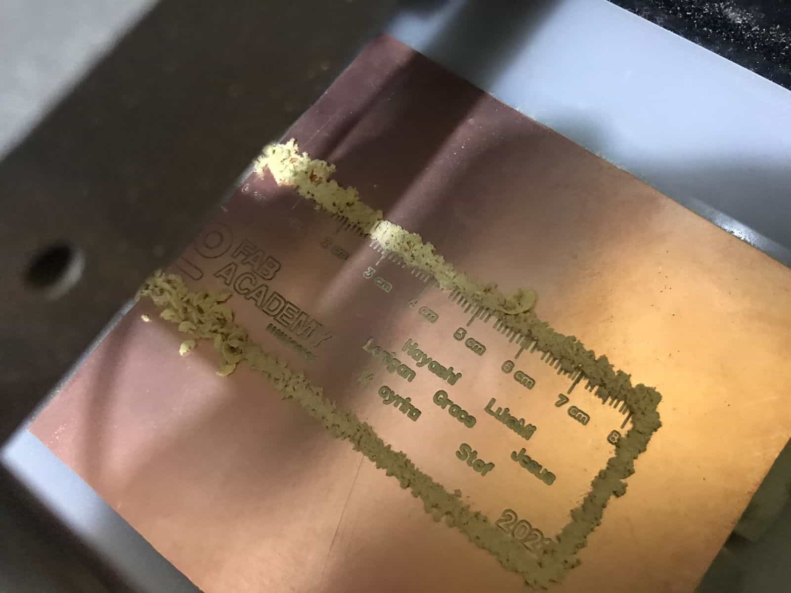
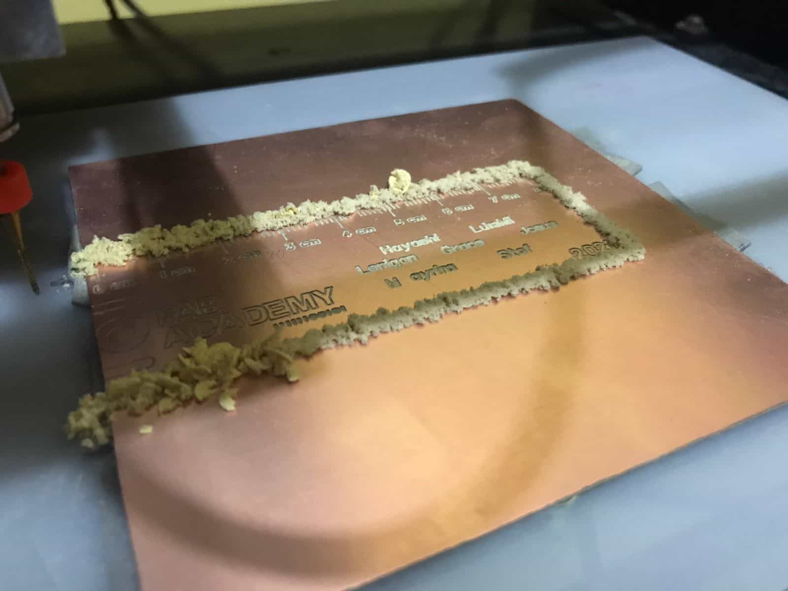
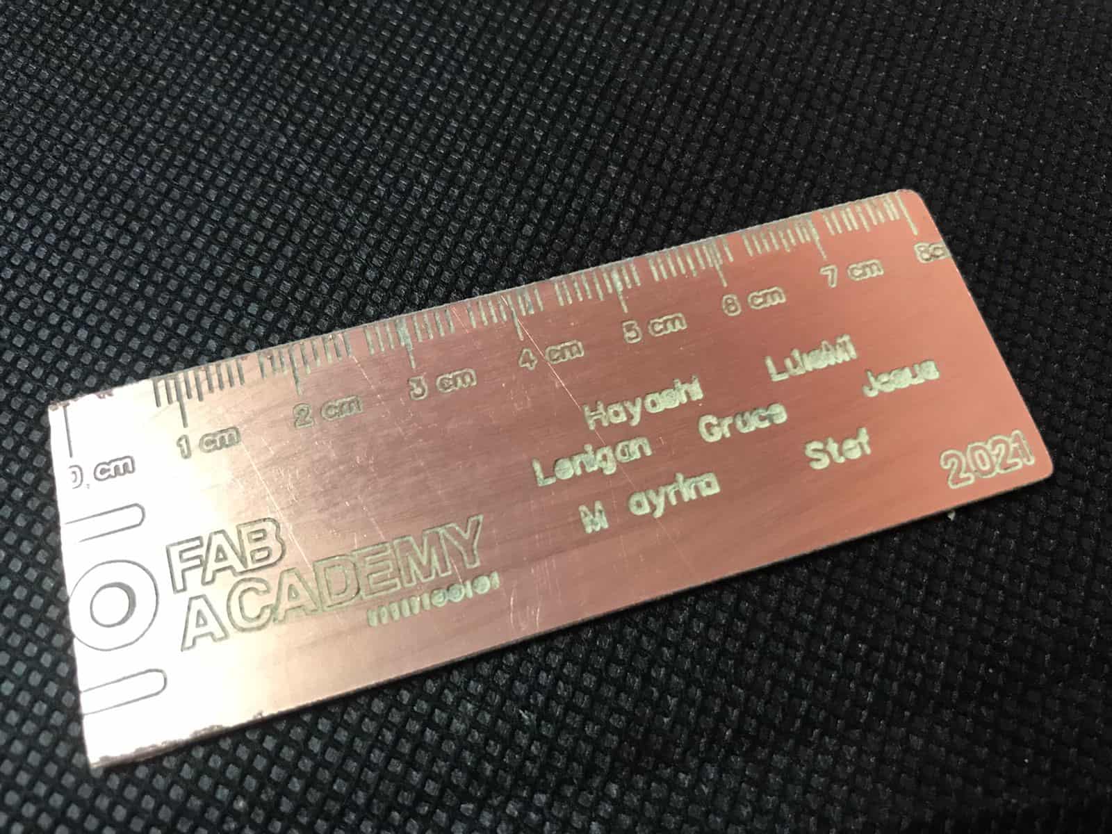
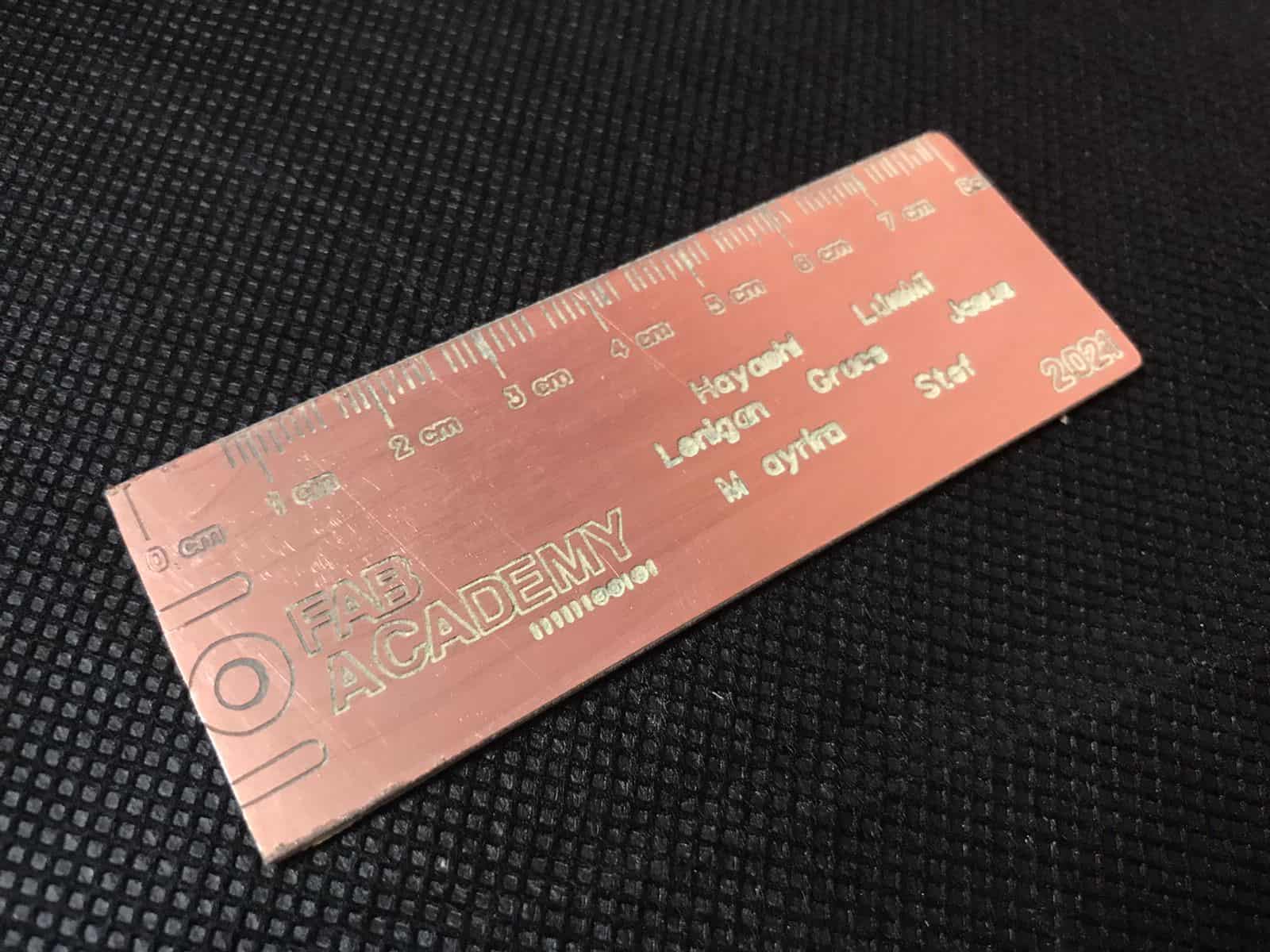
- And finally, the Fab Lat team chose to be innovative and use our own design for this assignment, our proposal is a kind of ruler to be able to use and know the measurements of our electronic components, this ruler is engraved with the Fab Academy 2021 logo and the list of members. We did it! πŸ’“


Designing


Designing


Milling


Milling


Group result


Group result


10

Second Assignment

Individual Assignment

As an individual challenge we have to build an in-circuit programmer by milling and filling the PCB. What does this mean? Well, to build a predetermined board to be able to practice the handling of the milling machine and also to practice soldering at the micro level to place the components. Something I have never done before in my life. 😍

Working at Fab Lab and Home

Make an in-circuit programmer
by milling and stuffing the PCB

Well, to be able to take this step I had to start by recognizing the components I needed, after that we had the big challenges of looking for a store where to get them since in our laboratory there were none, besides, the challenging thing was that not all stores are open because we are still in pandemic, it has been crazy!

As I mentioned before, our milling machine was not available from the beginning of the week so it has taken us more time to cut our boards, fortunately we were able to acquire the components and in the days that we could not cut we took the opportunity to learn about the programs for the virtual construction of the boards. Very interesting! πŸ˜ƒ


My PCB


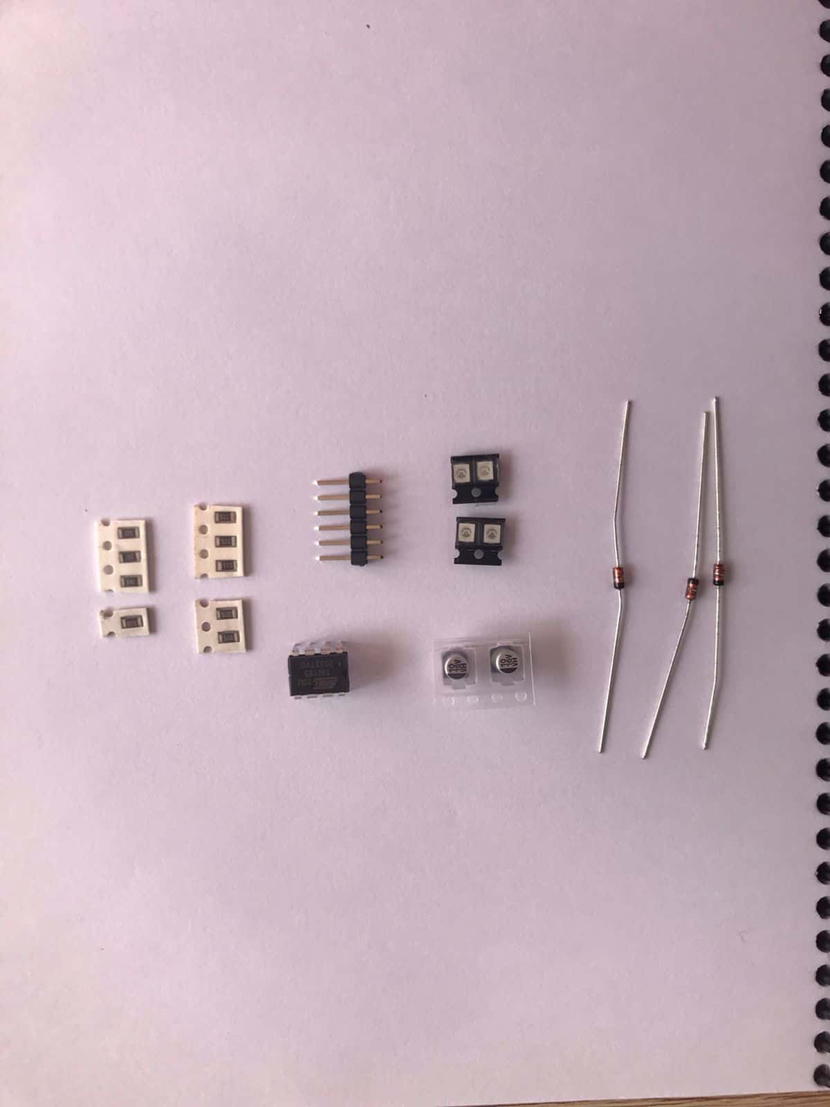
- Well, I chose to make the UPDI with the ATTiny85 because in Lima you can get the necessary components to build it, the others are not easy to find, we asked in the stores and there were none. We coordinated it with the team to be able to buy among all since it is not allowed to walk around the city without permits. One of us had to buy the one for everyone. The cost of this KIT was S/.50.00, according to my fellow electronics connoisseurs they say that they are expensive and that maybe it is due to the low demand since not all stores are available.


Purchased components


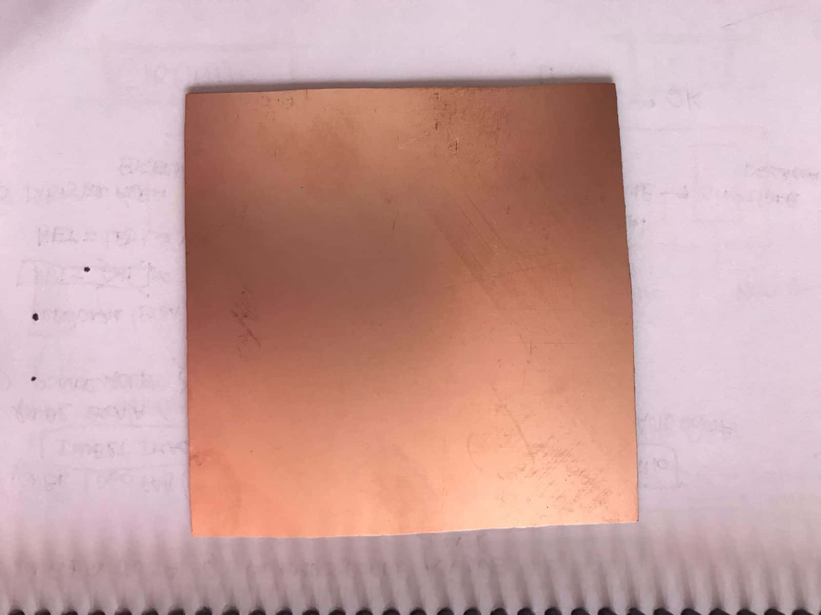
PCB 10 x 10cm


Components


1.8-2.3V red smd led diode
1.8-2.3V green smd led diode
1k resistence (1000=102[10 y 2=00] Ohms)
SMD resistence 510 (Ohms)
SMD resistor 511 (Ohms)
ATtiny85 8-Bit Microcontroller


Software


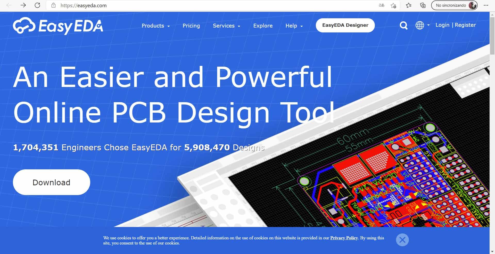
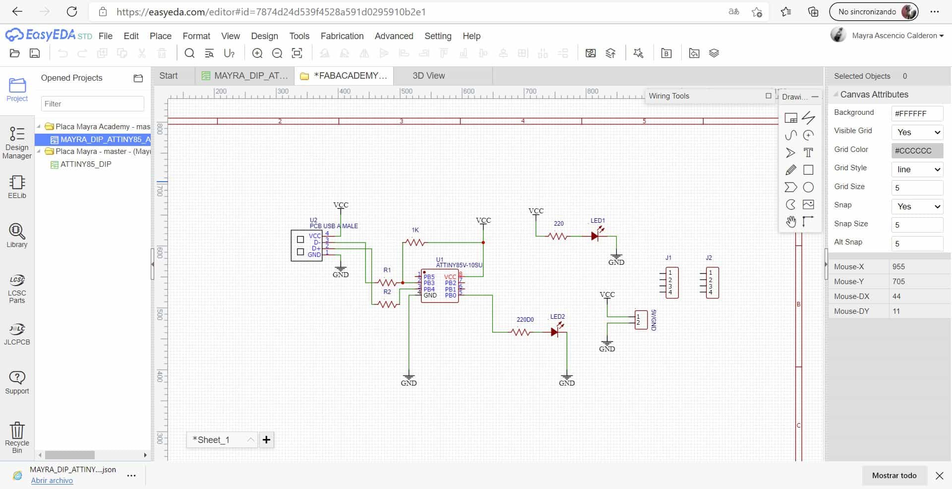
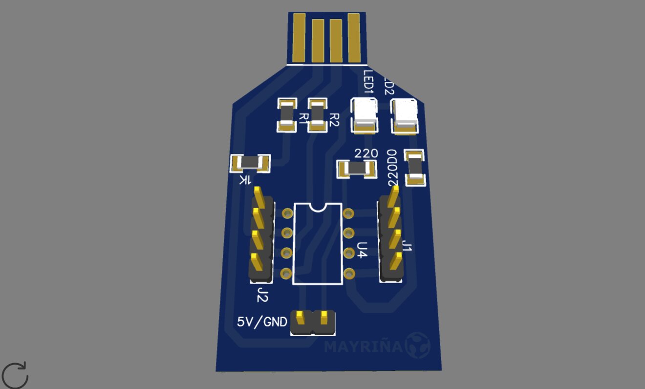
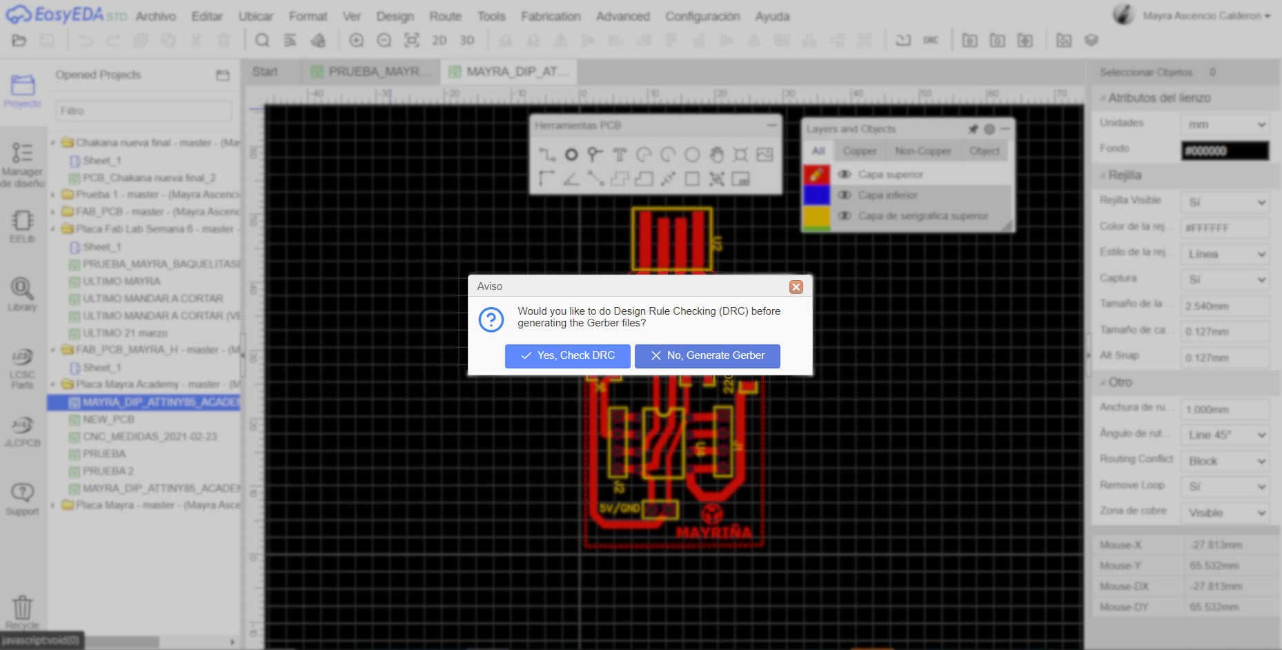
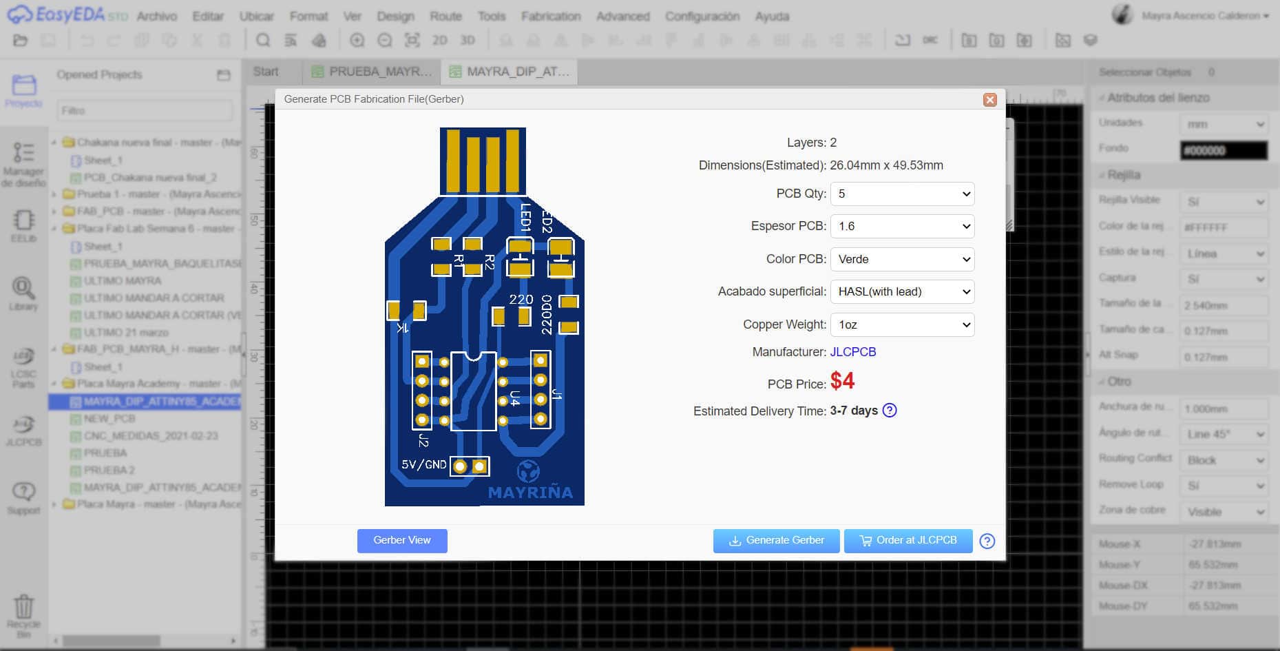
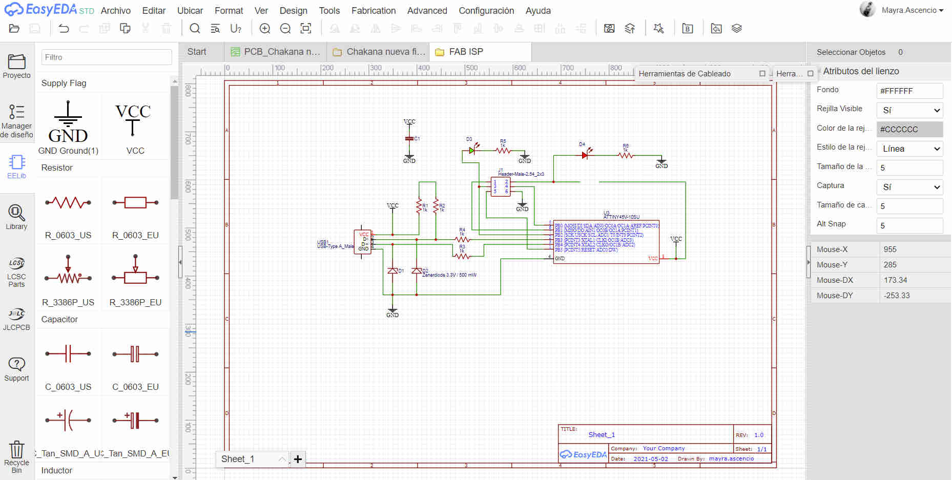
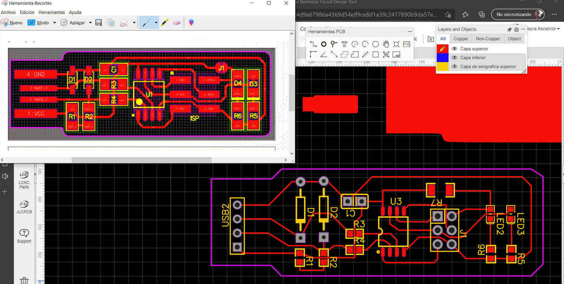
- In order to build this board design we use the EasyEDA program, it is a free online software that allows you to easily build the circuits and send them ready to manufacture. This program has many benefits, to start getting familiar with it we took a default design to learn the design process.


Software


Workspace


PCB


Circuits


3D


3D


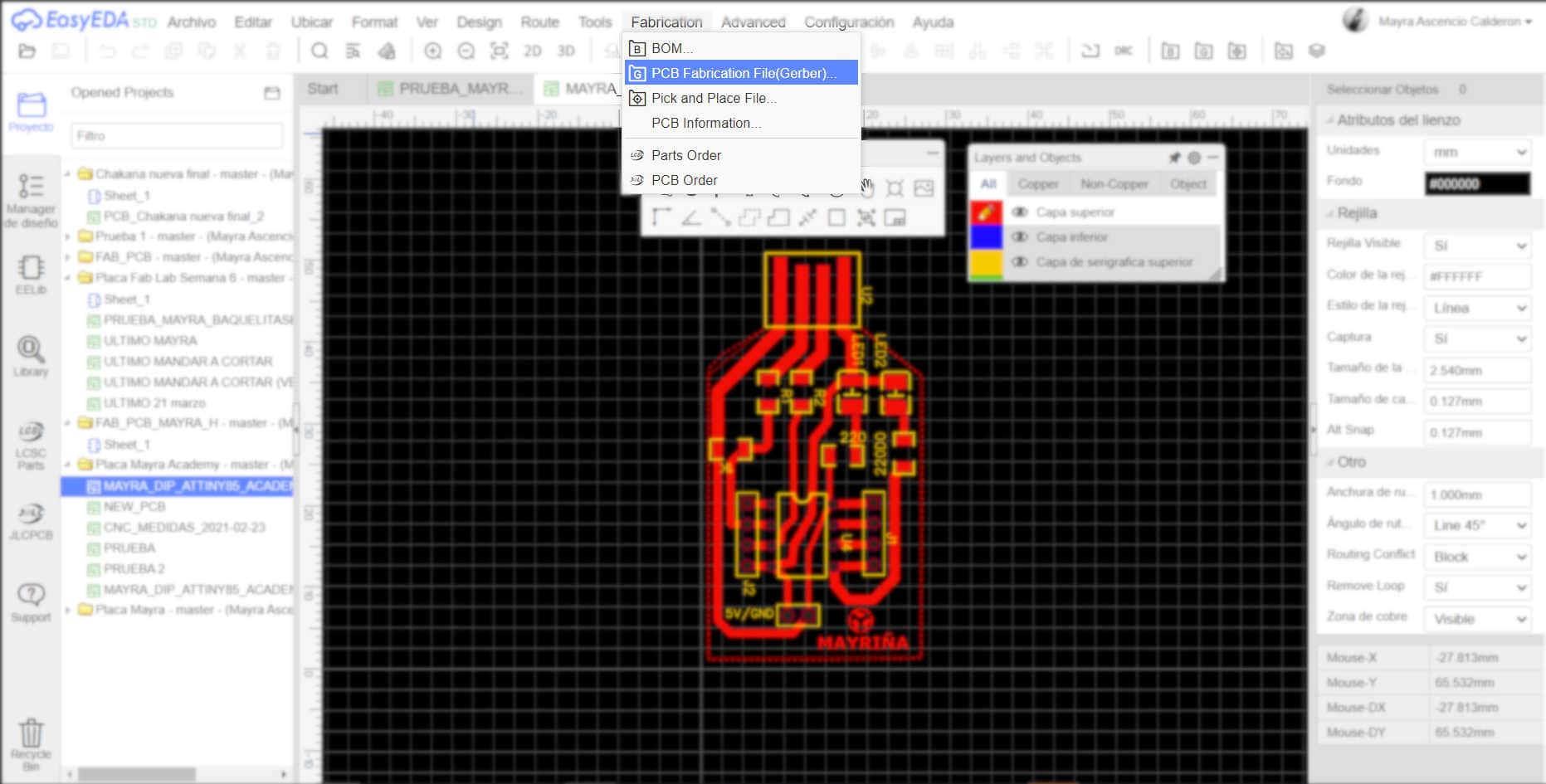
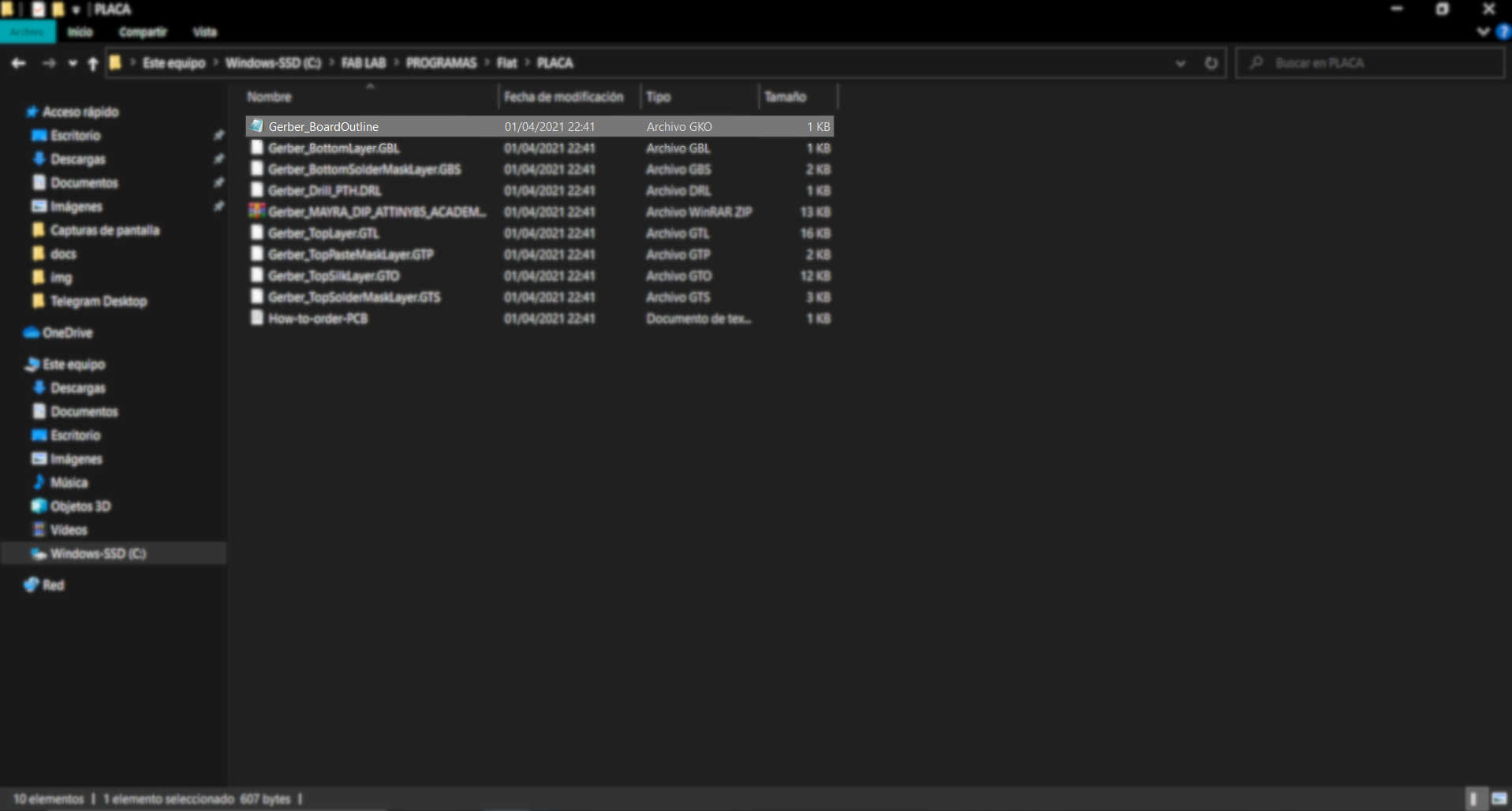
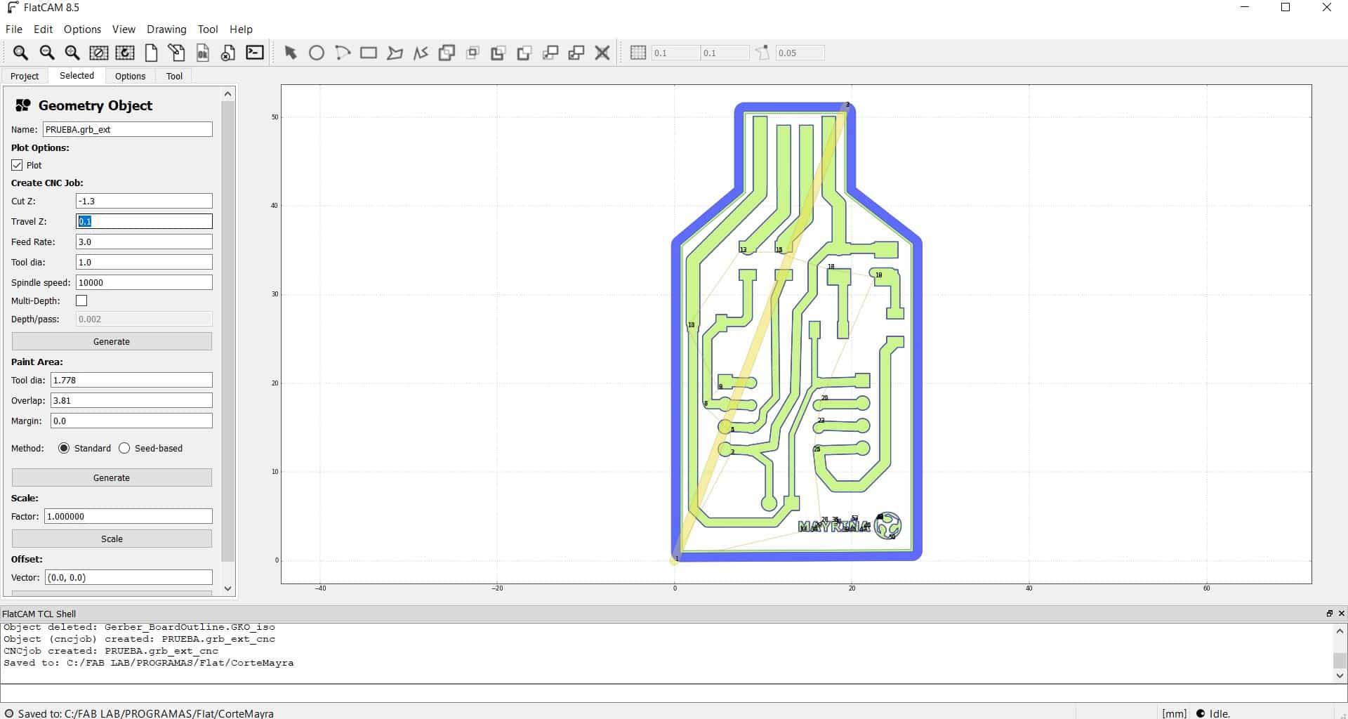
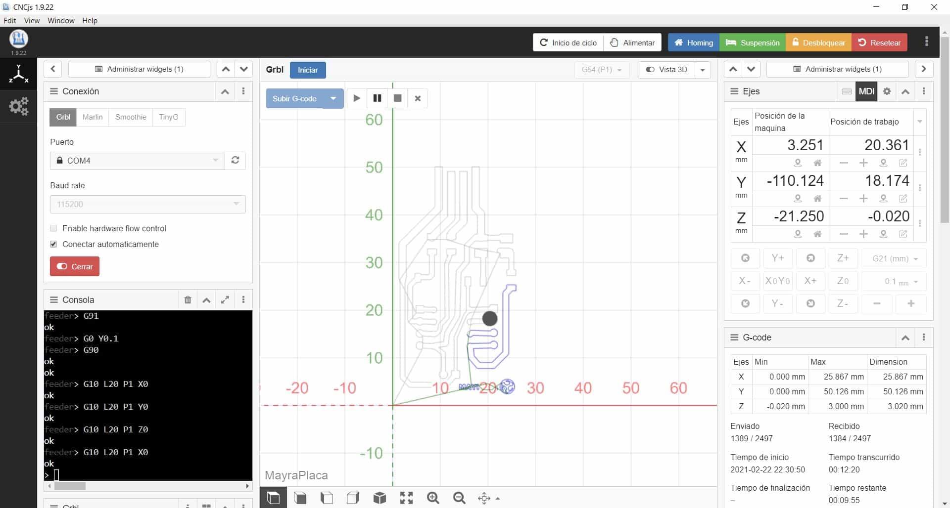
- After using EasyEDA we need to go through two more programs, one is FlatCAM and the other is CNCjs. I did not know both programs but I realized that the operation was neither easy nor difficult, it is necessary to generate the defined parameters to have a good milling and cutting, otherwise the plate will not come out with the result we want. It is interesting to see that by millimetric parameters we can make big mistakes, a lot of caution is needed to work with a milling machine.


How to export


Push no, generate gerber.


Generate Gerber (download)


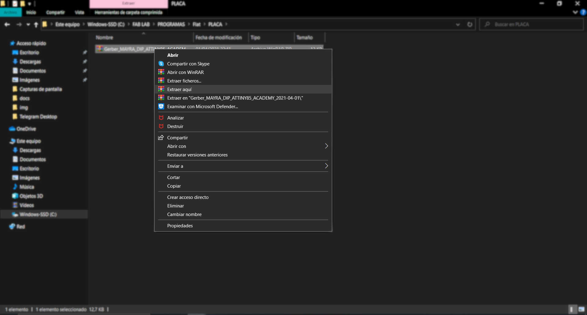
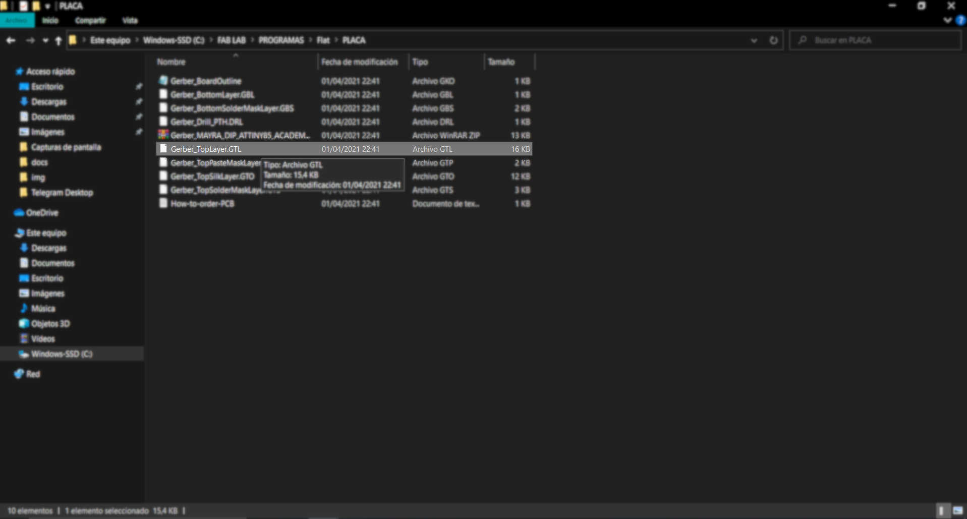
Extract ZIP


Use top layer for traces


Use Board Outline for cut


Open Gerber


Milling program


First Attemp


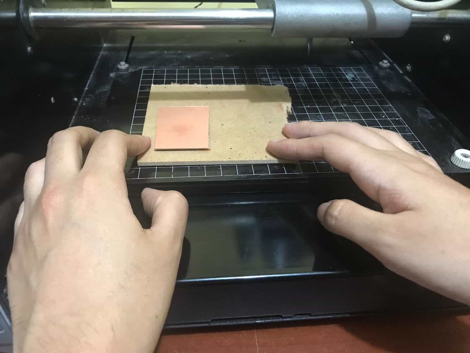
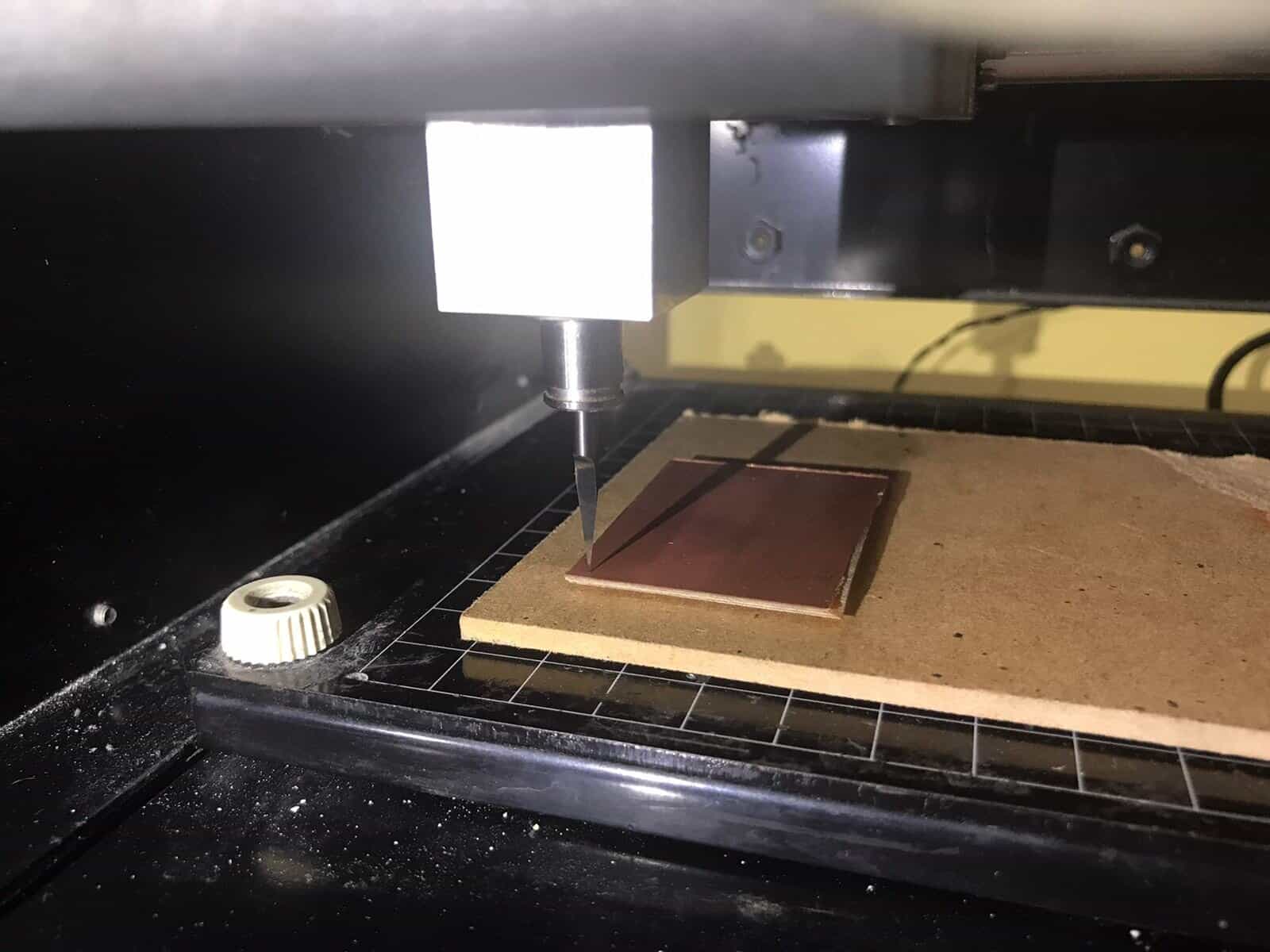
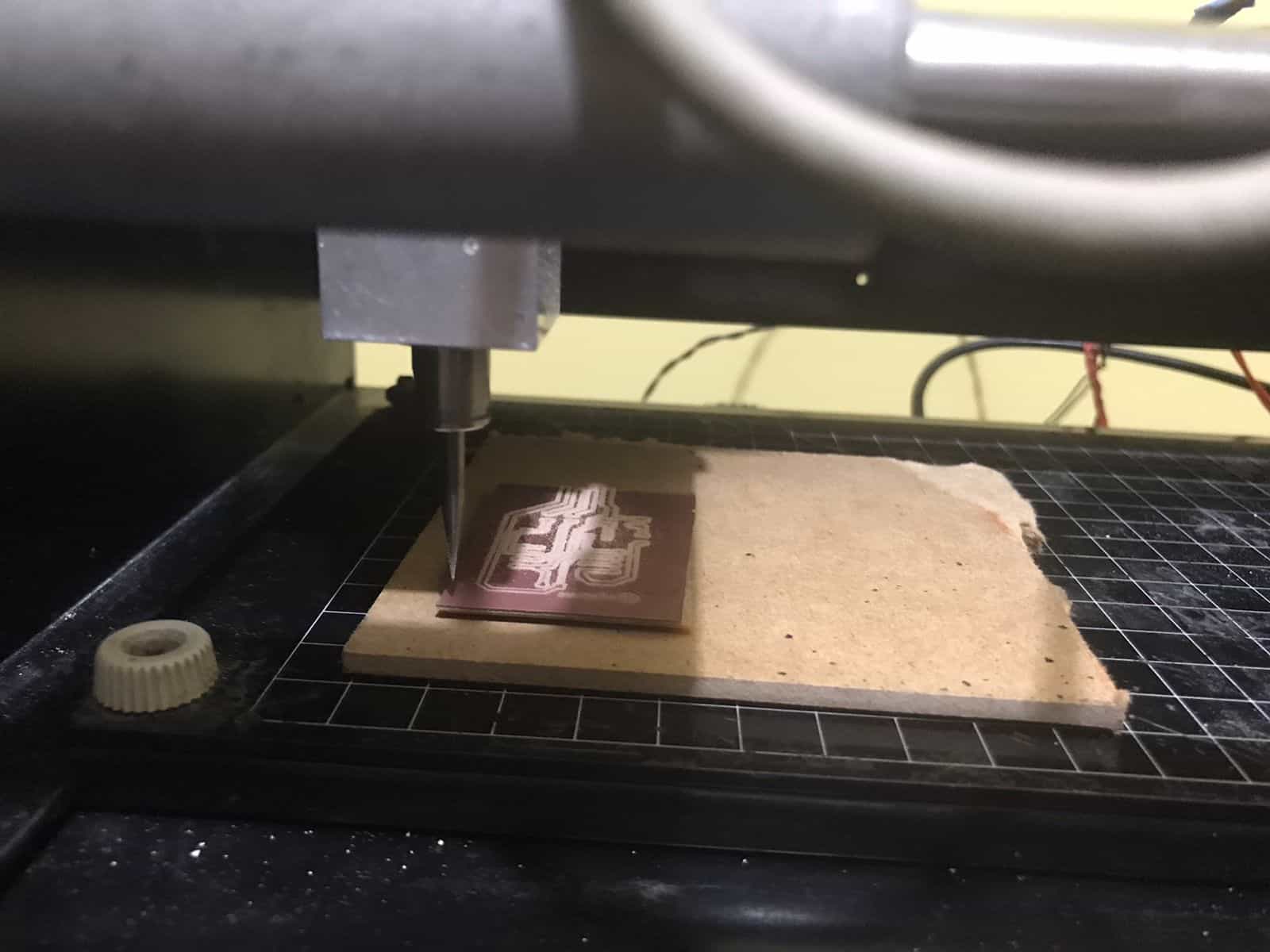
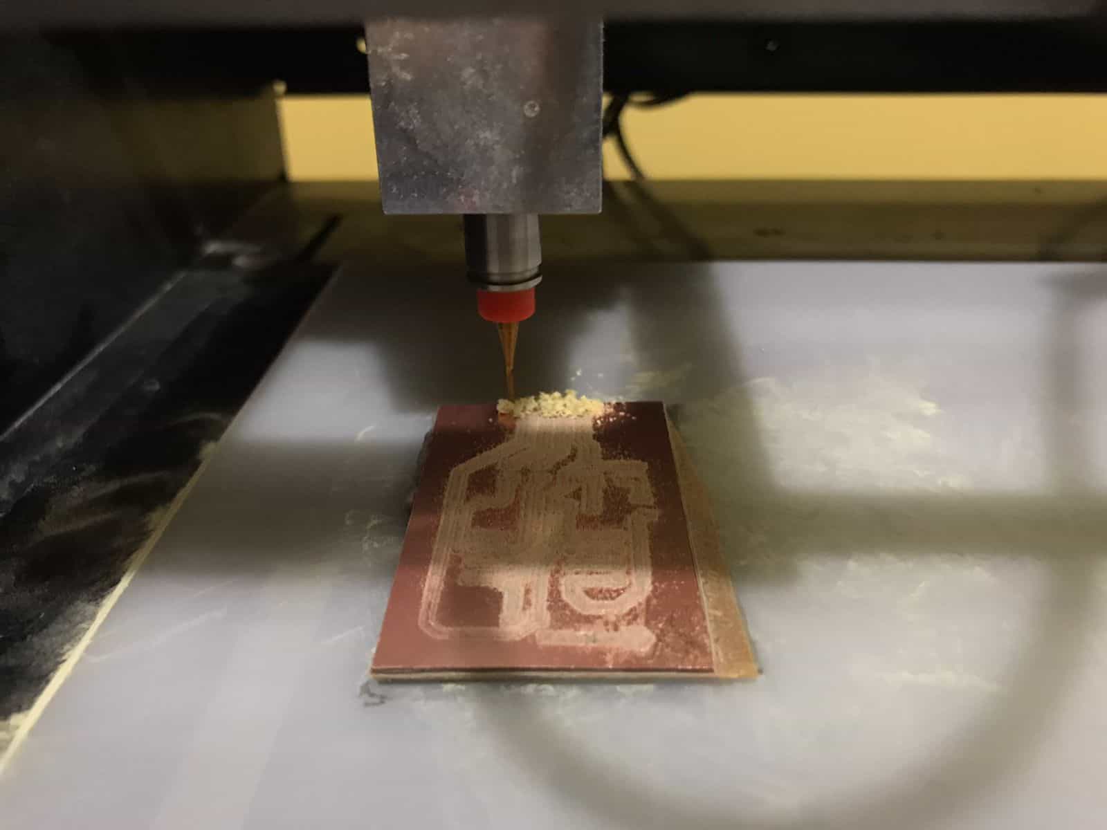
- After calibrating and setting the necessary parameters in the programs I made the first attempt at milling, this time I did it at home because the lab hours are restricted to 6 pm and it is not enough time to do the tests. It has been very interesting to have all the possible machines at home. 😍


Placing bakelite


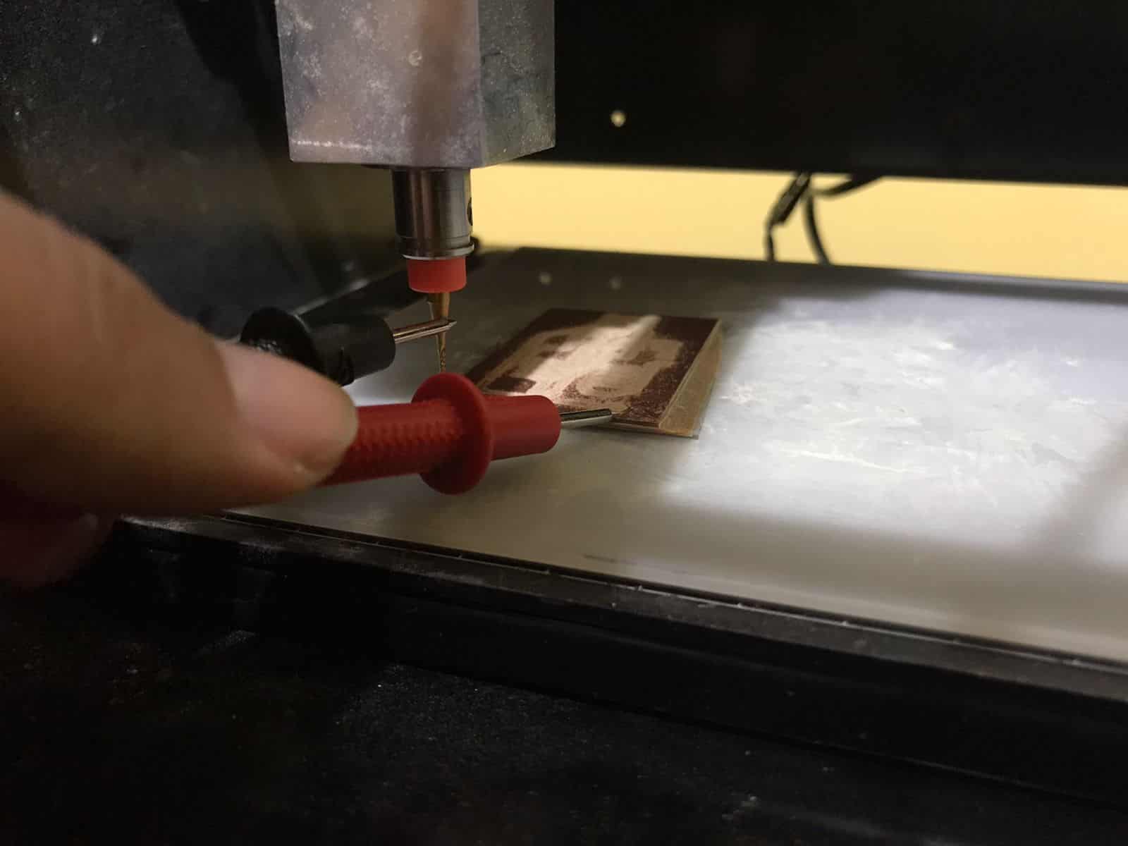
Milling cutter position


Milling plate


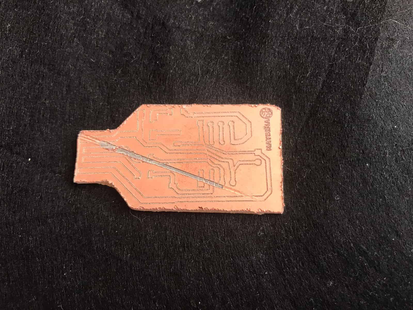
First result


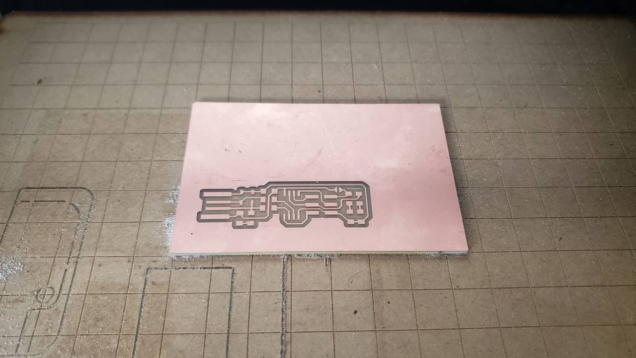
- This first result had several flaws, first of all due to the bad calibration of the machine, it can be seen that the external cut does not match the position of the internal milling. Secondly, at the time of cutting I did not place the depth of the milling cutter at the necessary height so that it would not rub diagonally across my plate. An additional point is that the letters I placed at the bottom were not large enough to be noticeable, it is readable but I think it could be larger.


Second Attemp


- On the second attempt I had problems with the milling machine, I placed the calibration that should work but it did not respond, the sacrificial bed that I placed (made of a piece of mdf) began to move and look a little curved, I did not think this could change the accuracy of the milling machine work but it did, that night I did not continue with the tests because I ran out of Bakelite. It was frustrating. πŸ˜₯


Changing parameters


Changing parameters


Tests


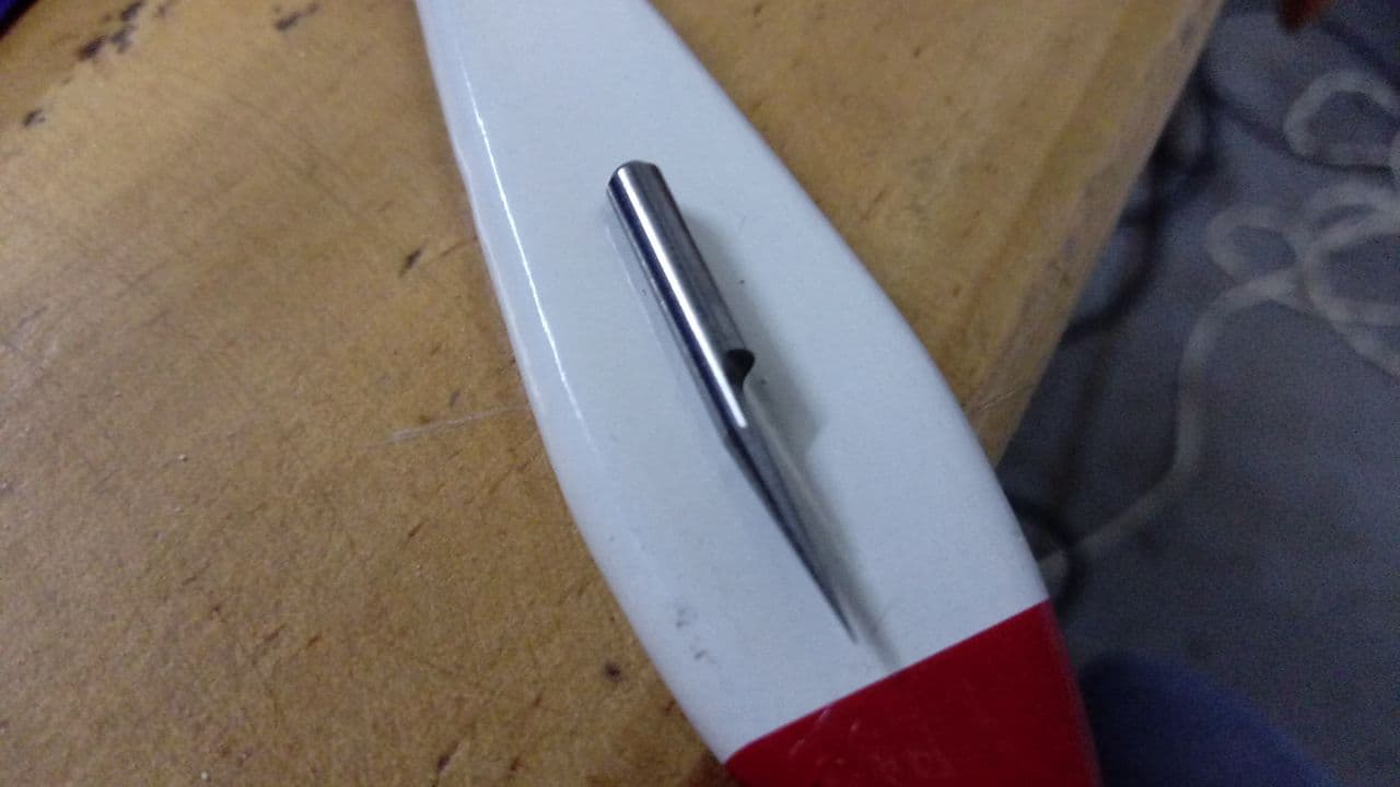
Milling cutter


Third Attemp


- This time I took the machine home again, we had already been successful in some tests in the fab lab so I was happy to have my board milled. Everything was fine until I did a test run, the parameters I used were fine but what was wrong was the leveling of the double contact tape. We used a new acrylic sacrificial bed and it was much better but the tape I placed under the PCB was uneven, because of this the mill did not recognize the whole working area, here I show the results. πŸ˜₯


Incomplete


Incomplete


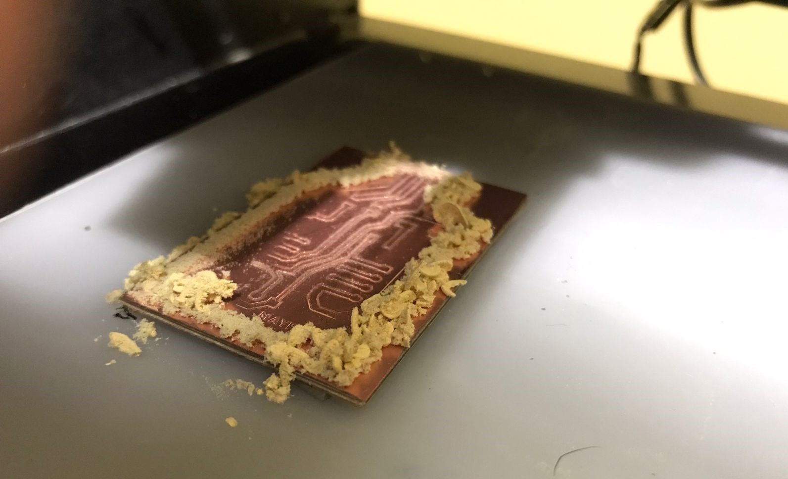
- In this third time I learned many more things about the parameters, the importance of the sacrificial bed, the correct use of the burs, the correctly positioned PCB, etc. Here I share the last attempt of my milling, after finishing it I sanded it with a water sandpaper because it is thin and allows me to clean the edges of the Bakelite. Now I have my board! 😍


Testing


Milling cutter


Milling cutter


Milling cutter


Soldering


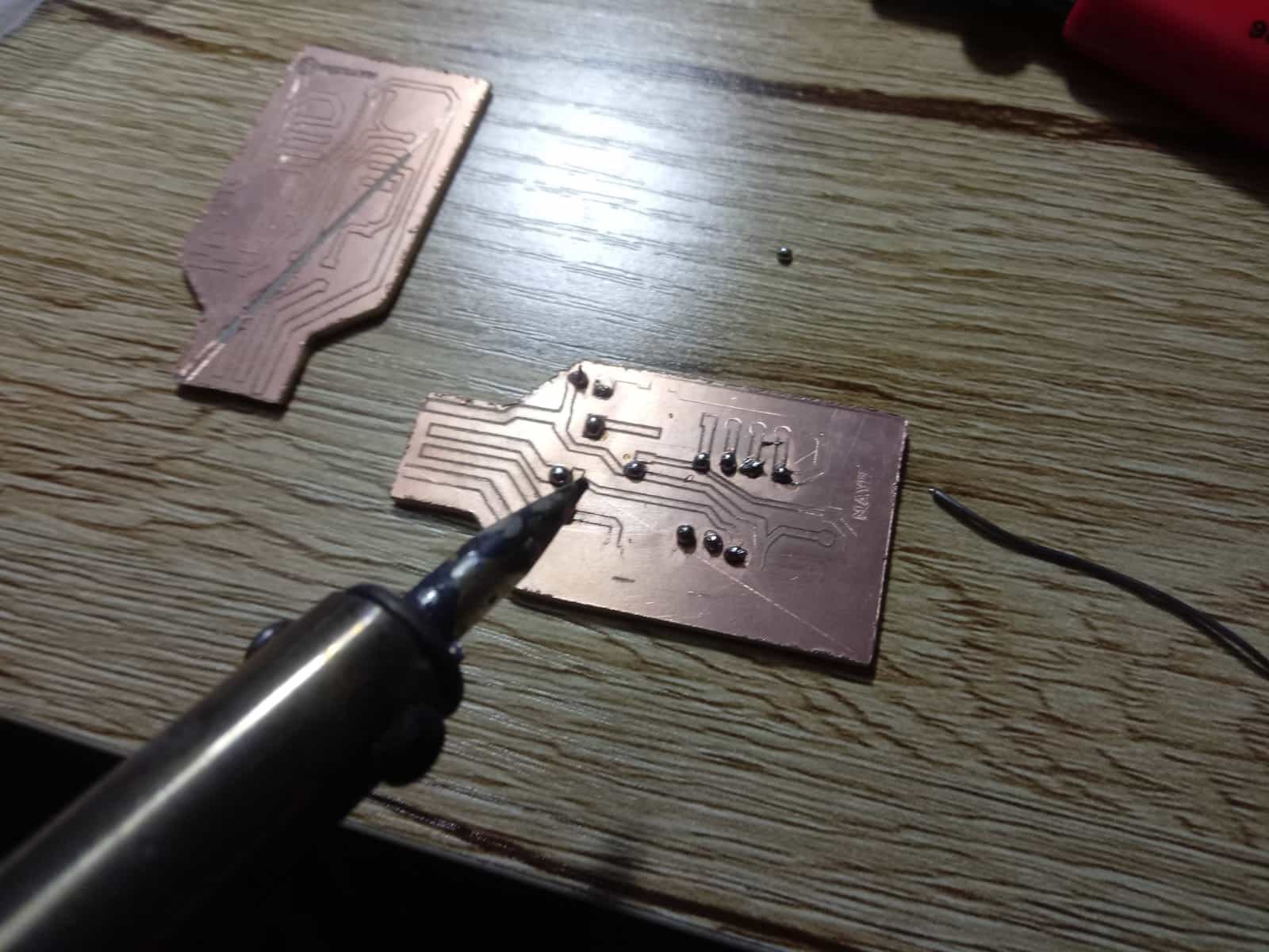
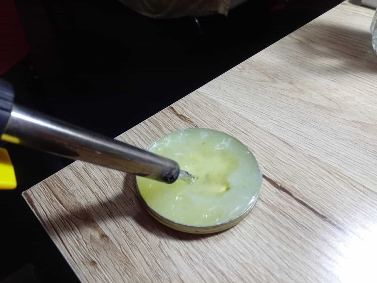
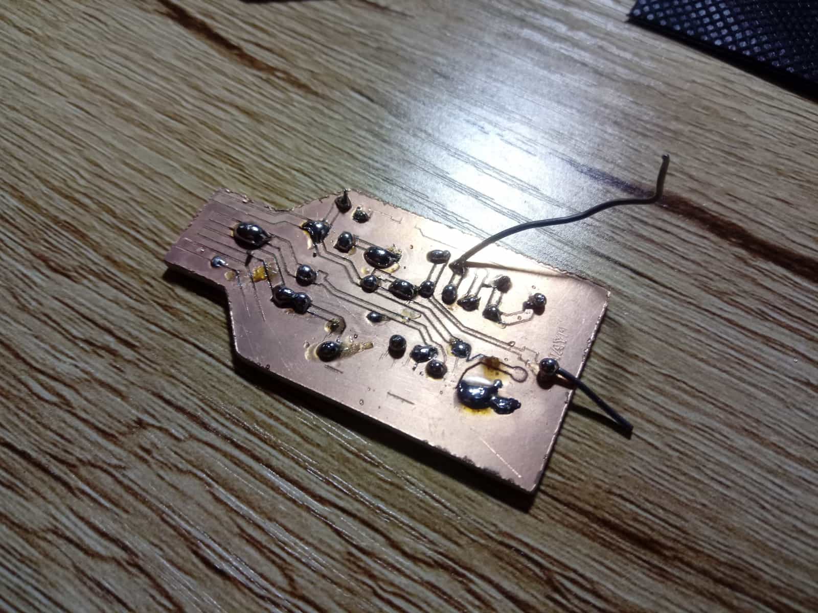
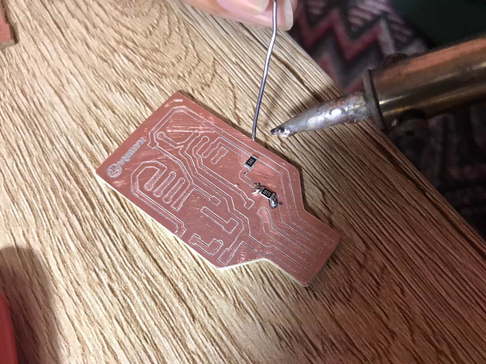
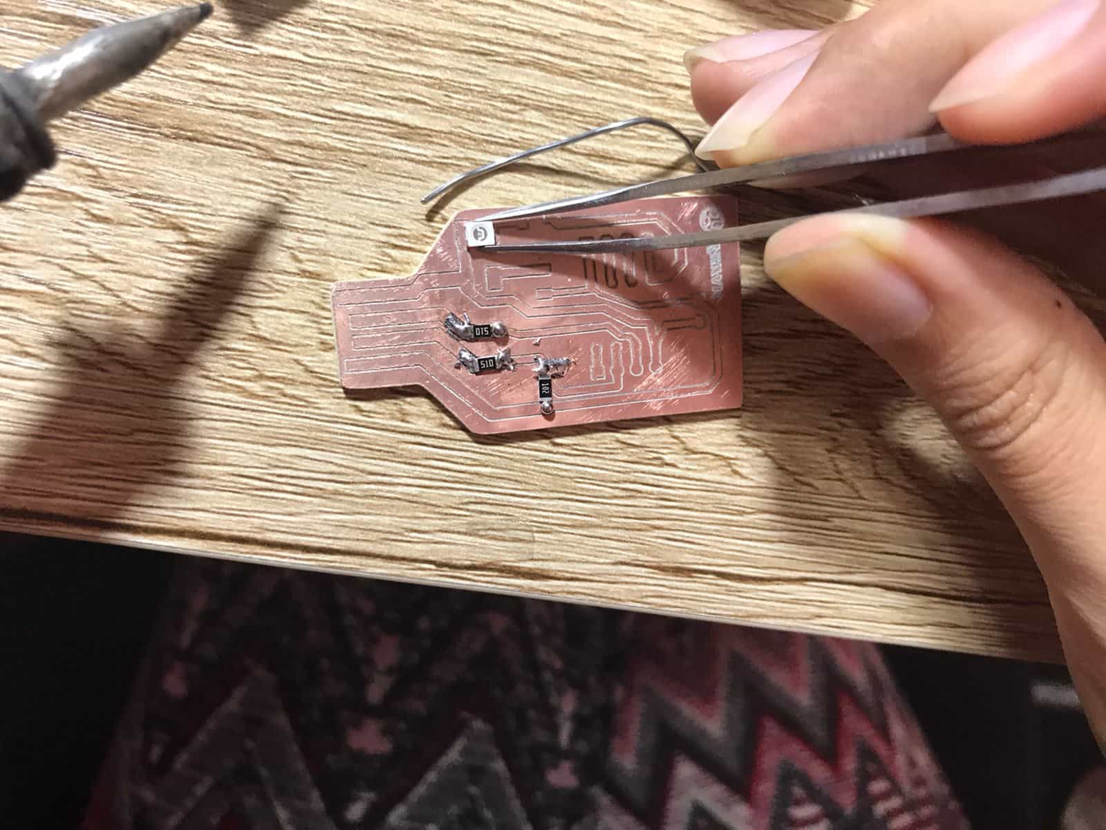
- It is the first time in my life that I have practiced soldering and even more of components as small as electronics, I am happy with my first experience but I will still need more and more practice, here I share with you some pictures of this great experience! 😍


Testing


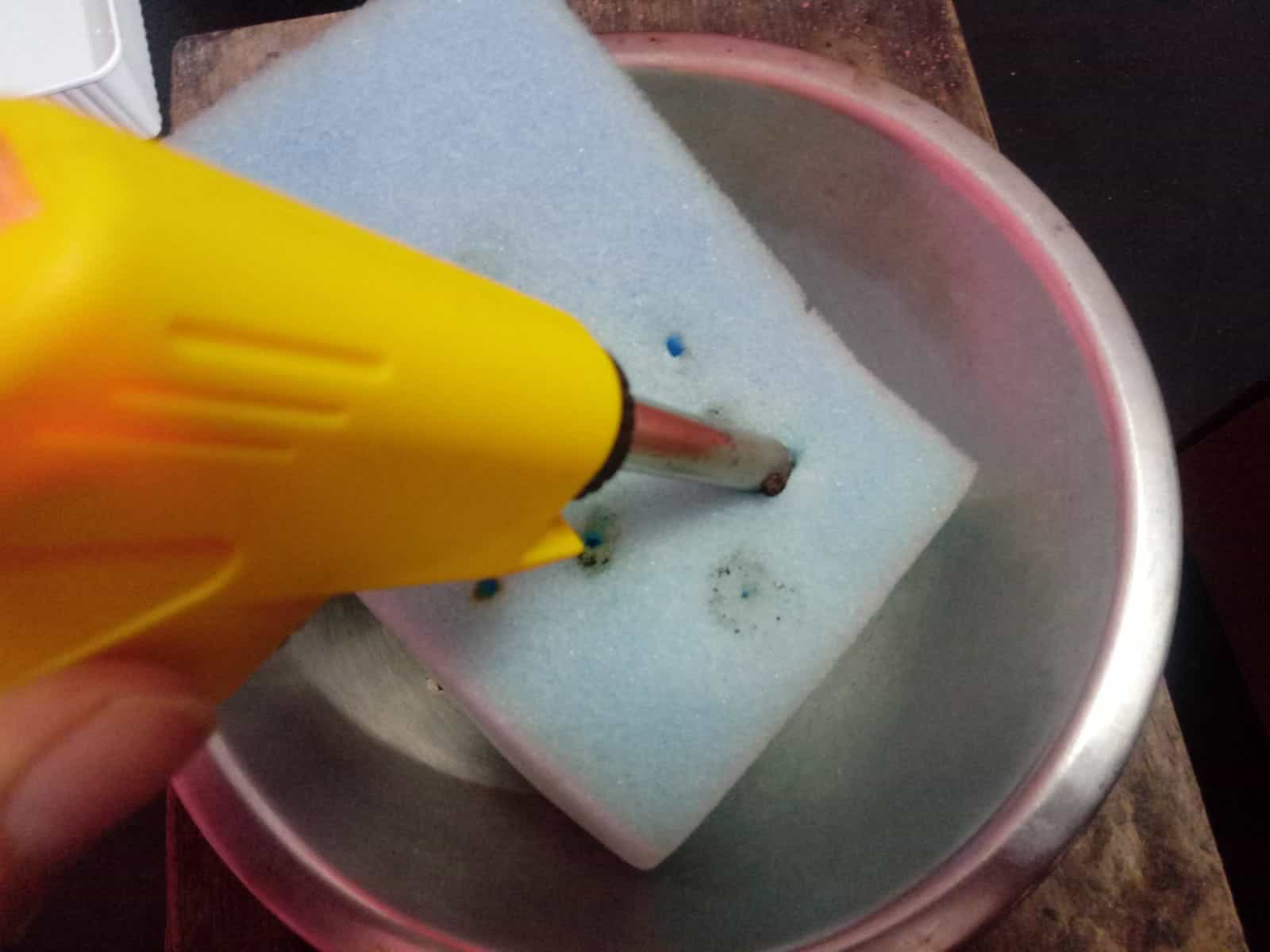
Solder paste


Sponge with water


First tests


Setting the resistors


Soldering the resistors


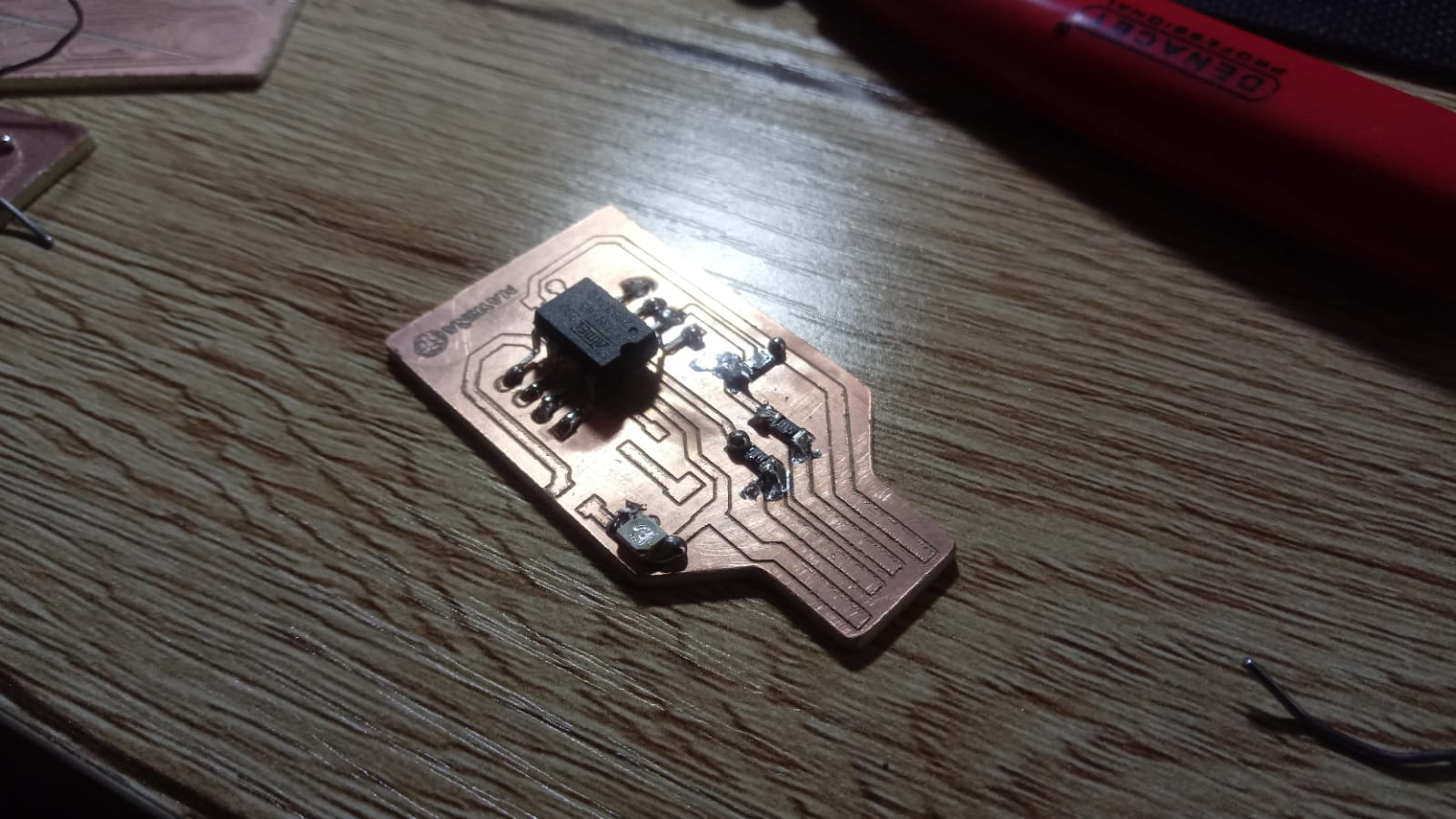
Attiny 85 ready


Milling cutter


Result


- Thanks to this process I have understood much more about the stages of building an electronic board, it has been a very intense and challenging week but with patience and teamwork many things can be achieved. Now I am performing the test to check the operation. πŸ’ͺ


10

Individual Assignment

FabISP of Brian

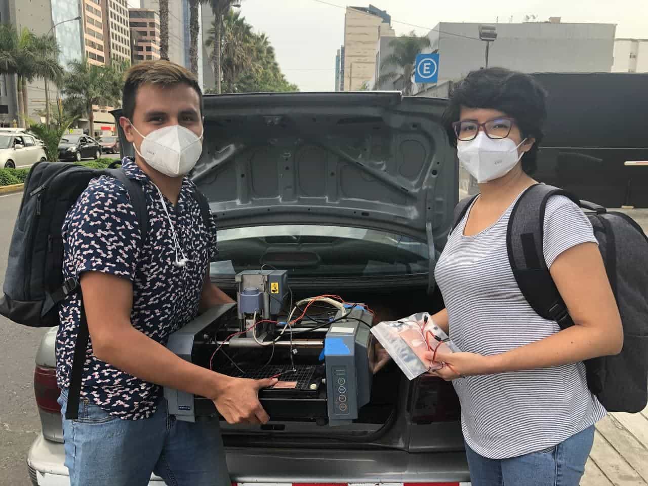
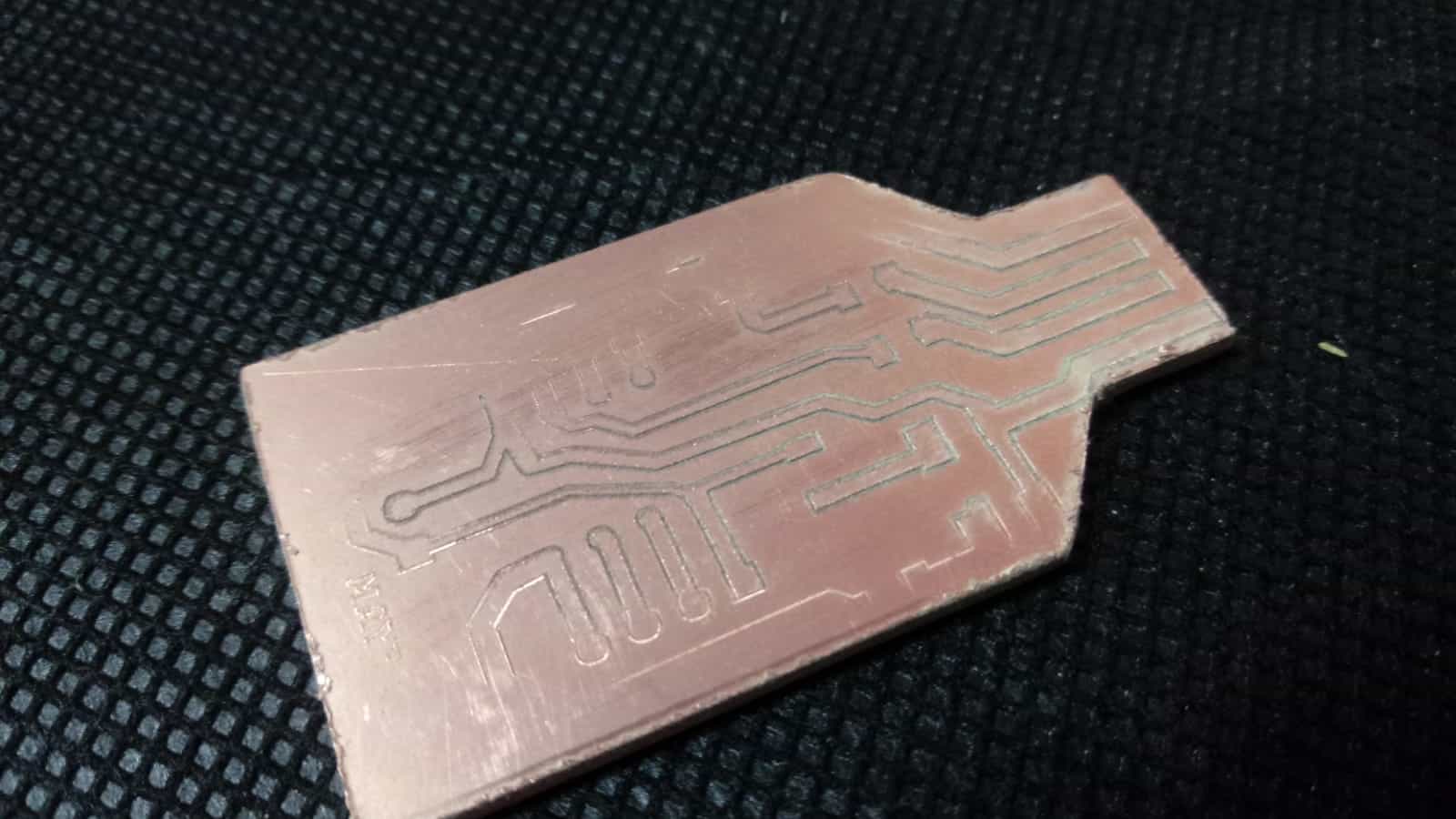
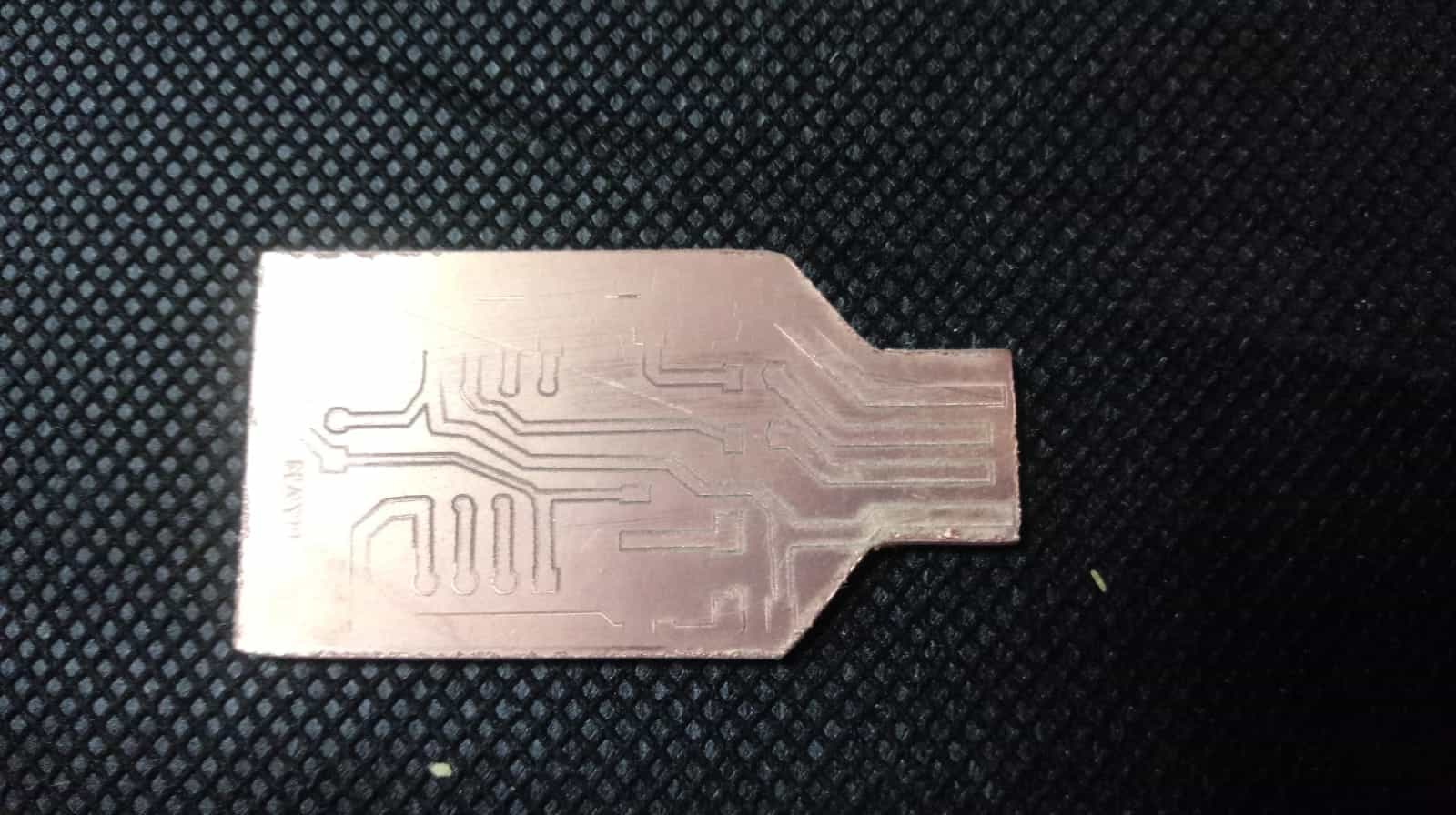
After a long time trying to make a board in our model we managed to make the FabISP, all this thanks to the support of several people and the follow up of my instructors from Barcelona. Obtaining this programming board was a marvel, next I will show all the journey I had to do to get it. 😍
I want to make a special thanks to my best partner in this Fab Academy; PSK 490 πŸ₯° for the management achieved with the Fab Lab ESAN thanks to them we were able to solve the milling and finally complete our task. πŸ₯°

The crossing

Make an in-circuit programmer
by milling and stuffing the PCB


In this new stage we had a lot of work to solve, after having used the machine for our first plates it was not difficult to make plates with smaller dimensions. In this case, as we needed a higher precision, our milling cutters were not the best and also the machine itself had some failures that prevented us from working.

It is important to consider that to achieve a fine work we have the necessary tools and machinery before doing the work, otherwise it will become an odyssey and will be very stressful for any student as it was for us. 😒


My PCB

My experience

The machine


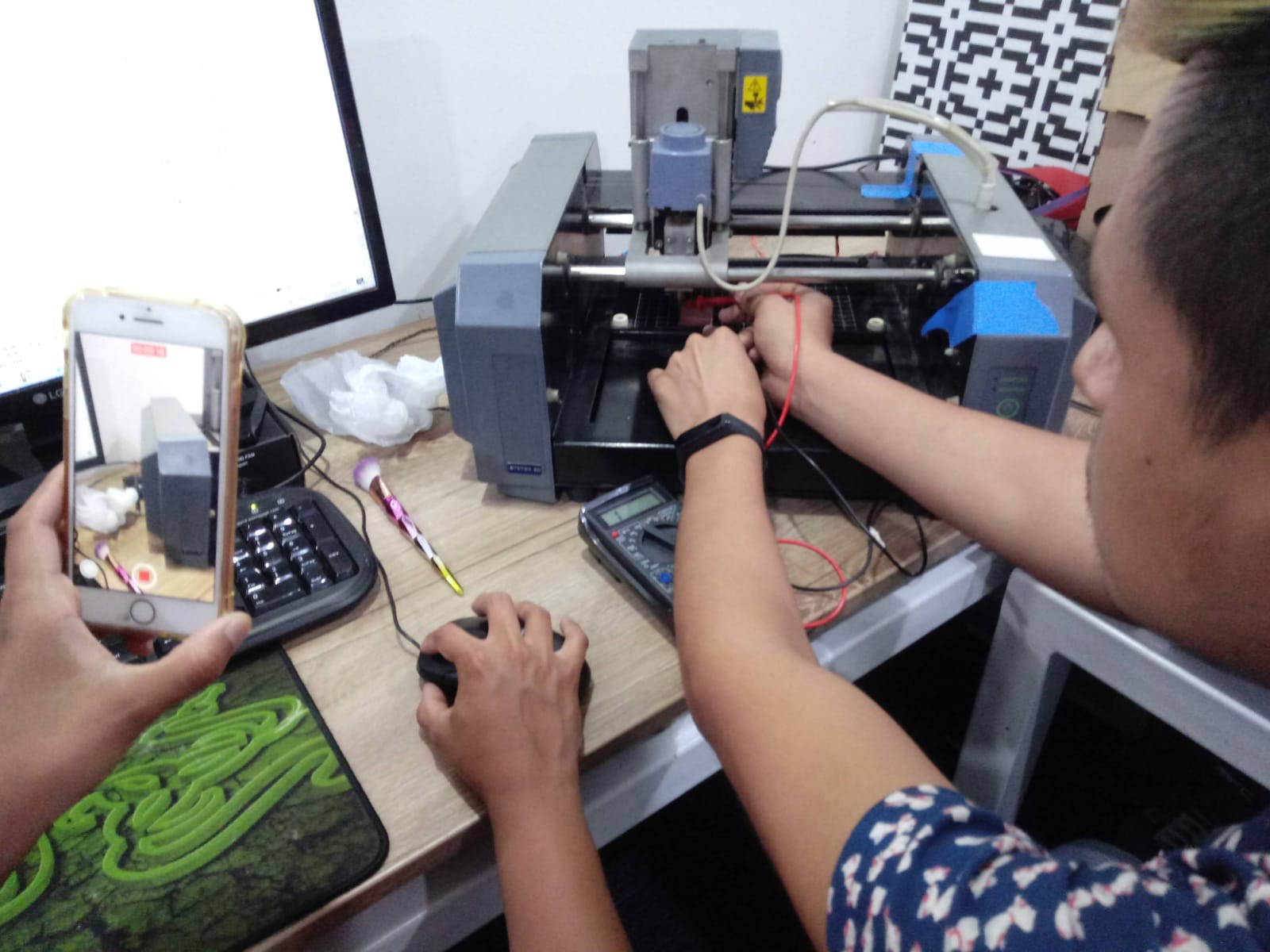
- Well, as I mentioned before, our model is to some extent different from any other model, this is because it has been hacked and because when we wanted to use it we have never been able to use the official program of the machine. Next I show some updated pictures of how the electronic part of the machine is connected.


Roland Modela MDX 20


Roland Modela MDX 20


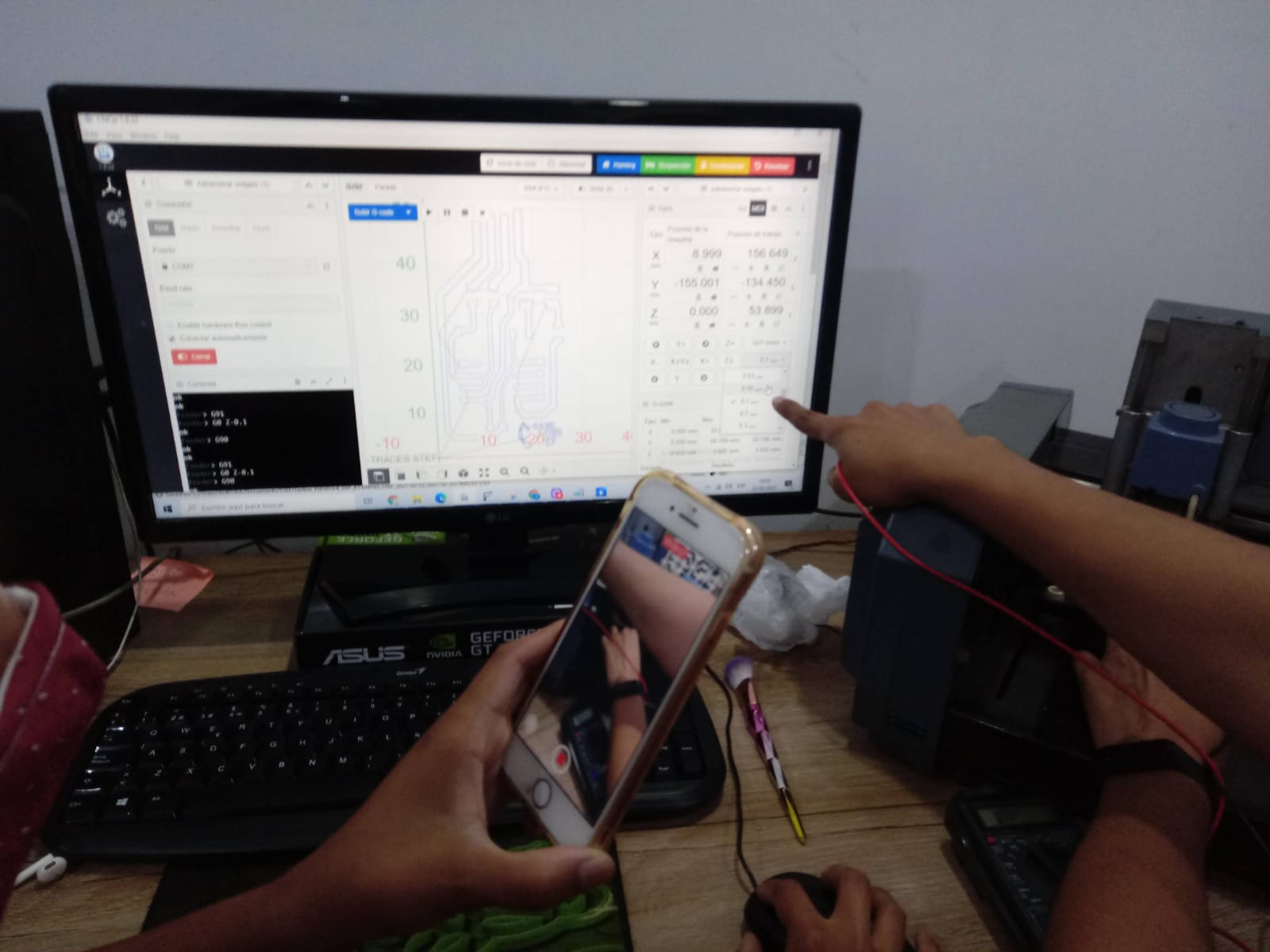
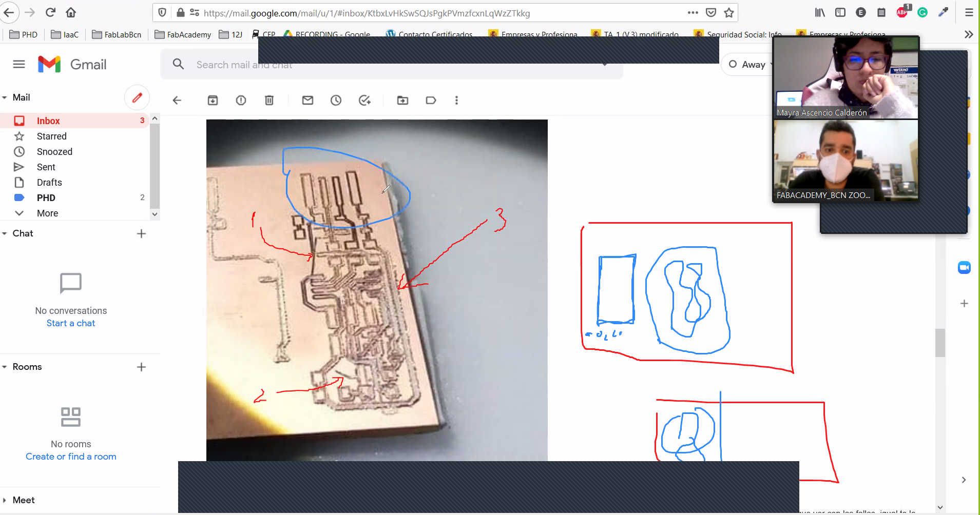
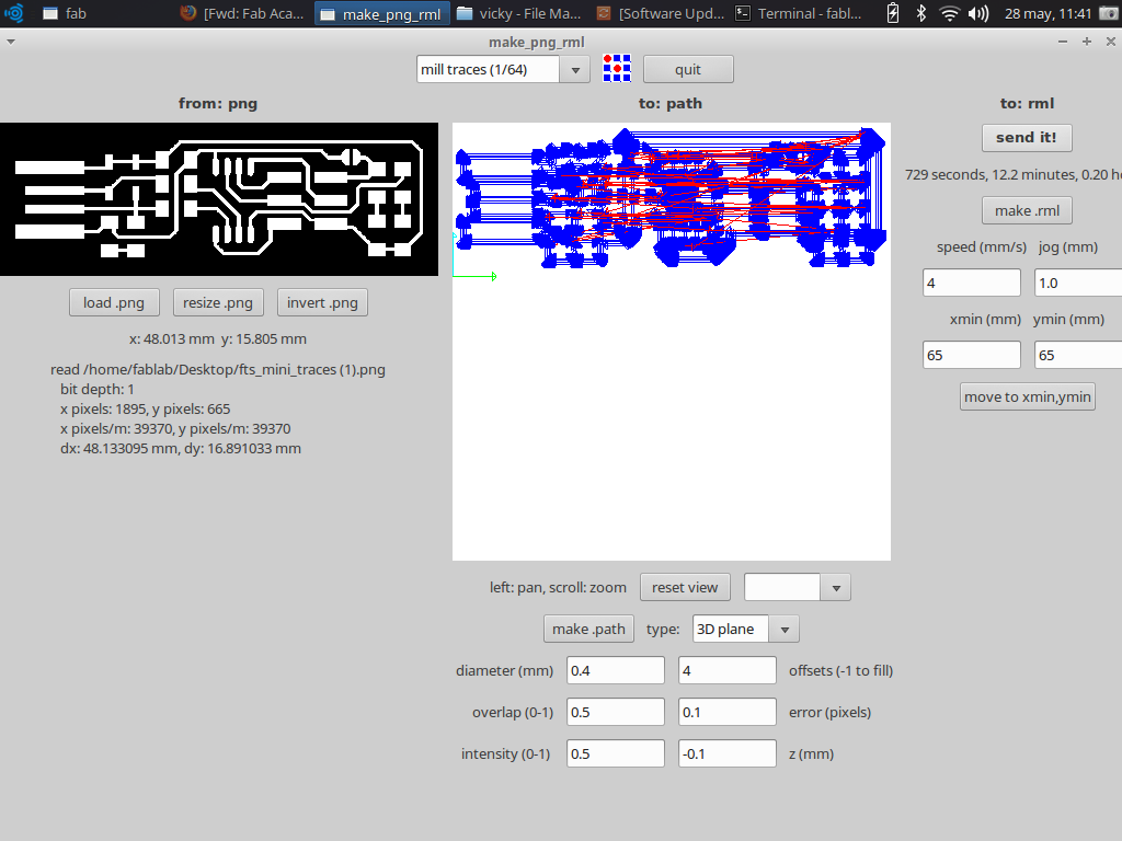
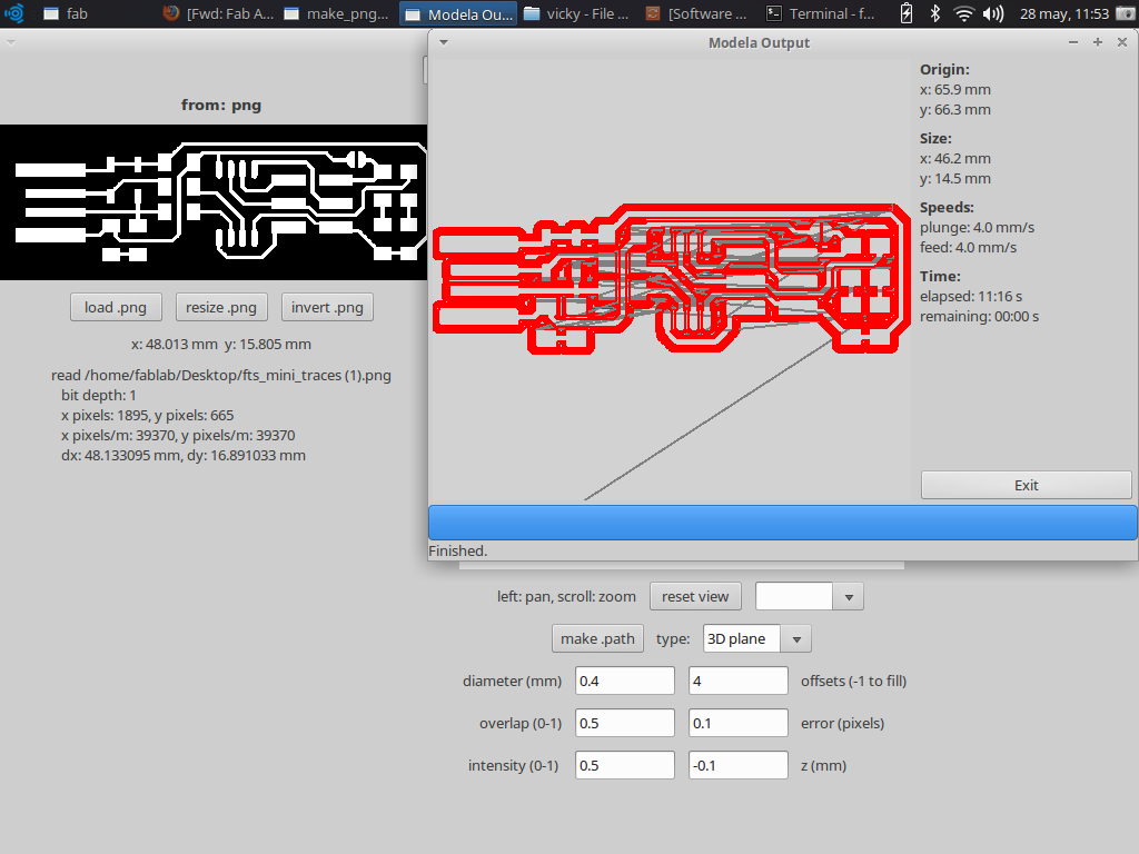
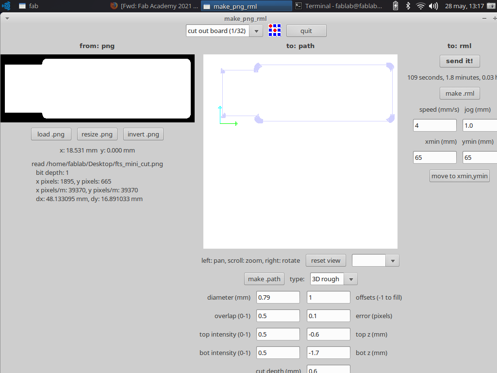
- One of the big problems we had was that apparently when the machine was set up, the HOME was not set, this was done manually and the specific problem is that when we finished milling and then cut the edge of the plate, it was out of phase cutting in another position. When I told this to my instructor he said he wanted to check the machine to see what was going on.


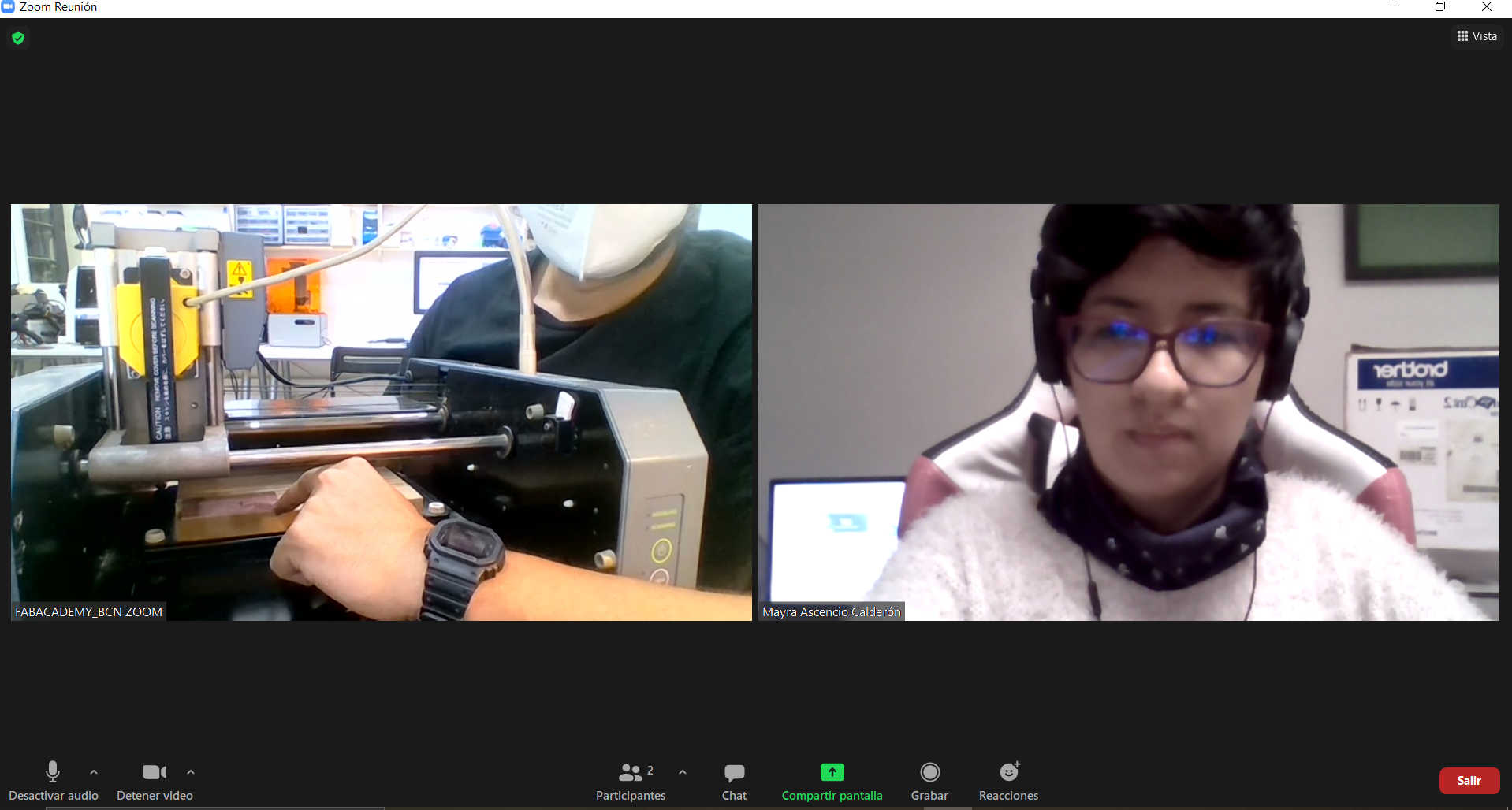
Meeting with Eduardo Chamorro


Meeting with Eduardo Chamorro


Meeting with Eduardo Chamorro


Meeting with Eduardo Chamorro


Meeting with Eduardo Chamorro


Meeting with Eduardo Chamorro


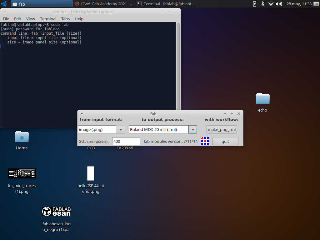
- As an indication and a way to solve this lag, he told me that I could alter the GCODE before sending the milling job to the machine, the changes were to remove the percentage symbol at the beginning and delete the M06, with this the machine would respond as it should without generating any lag.
Here I share some images of the tests I did after Eduardo's advice.


MODS


MODS


MODS


MODS


FaltCAM


CNCjs


Milling machine


Several attempts


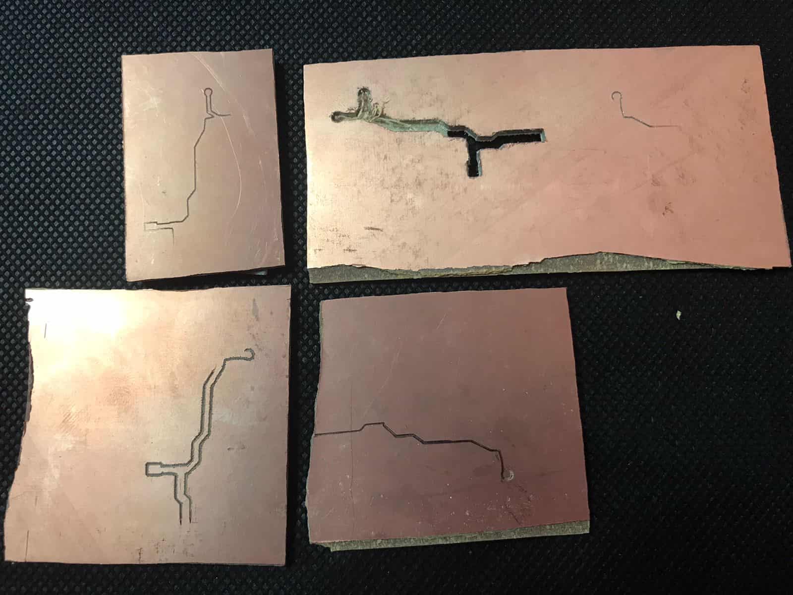
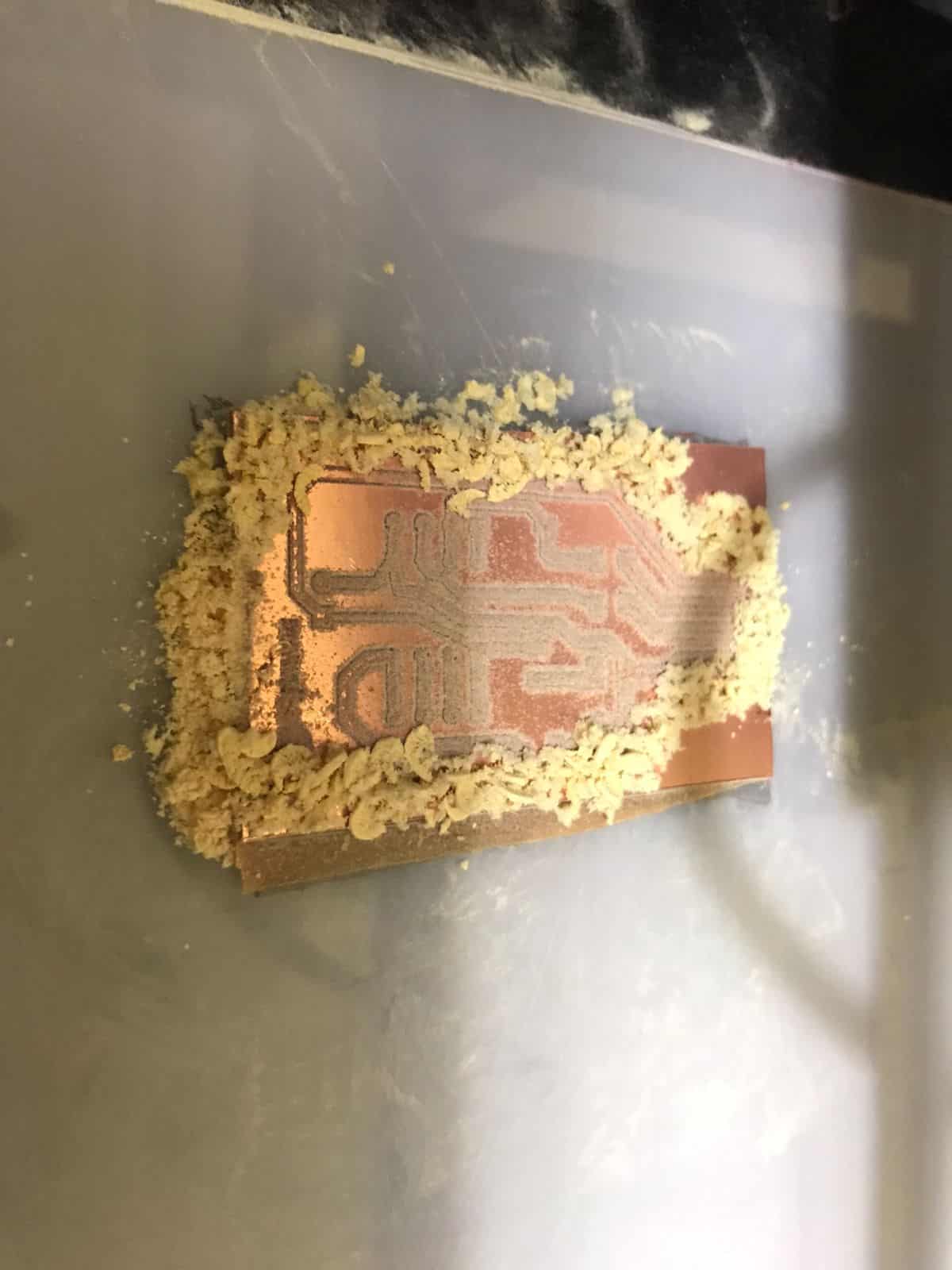
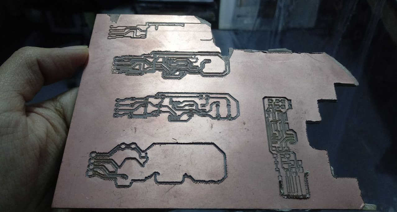
- After several attempts Stef and I thought it might be possible to build the plate from scratch so we tried to draw it in EasyEDA as close as possible and send it to be milled to have the same result. Here I show the attempts.


EasyEDA


EasyEDA


FlatCAM


Attempts


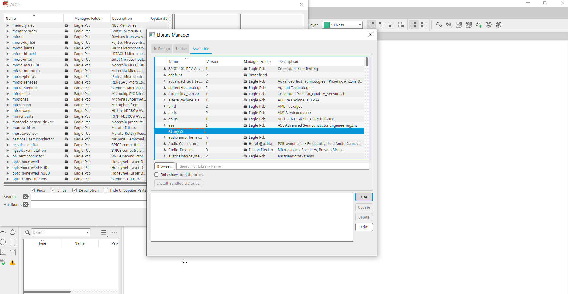
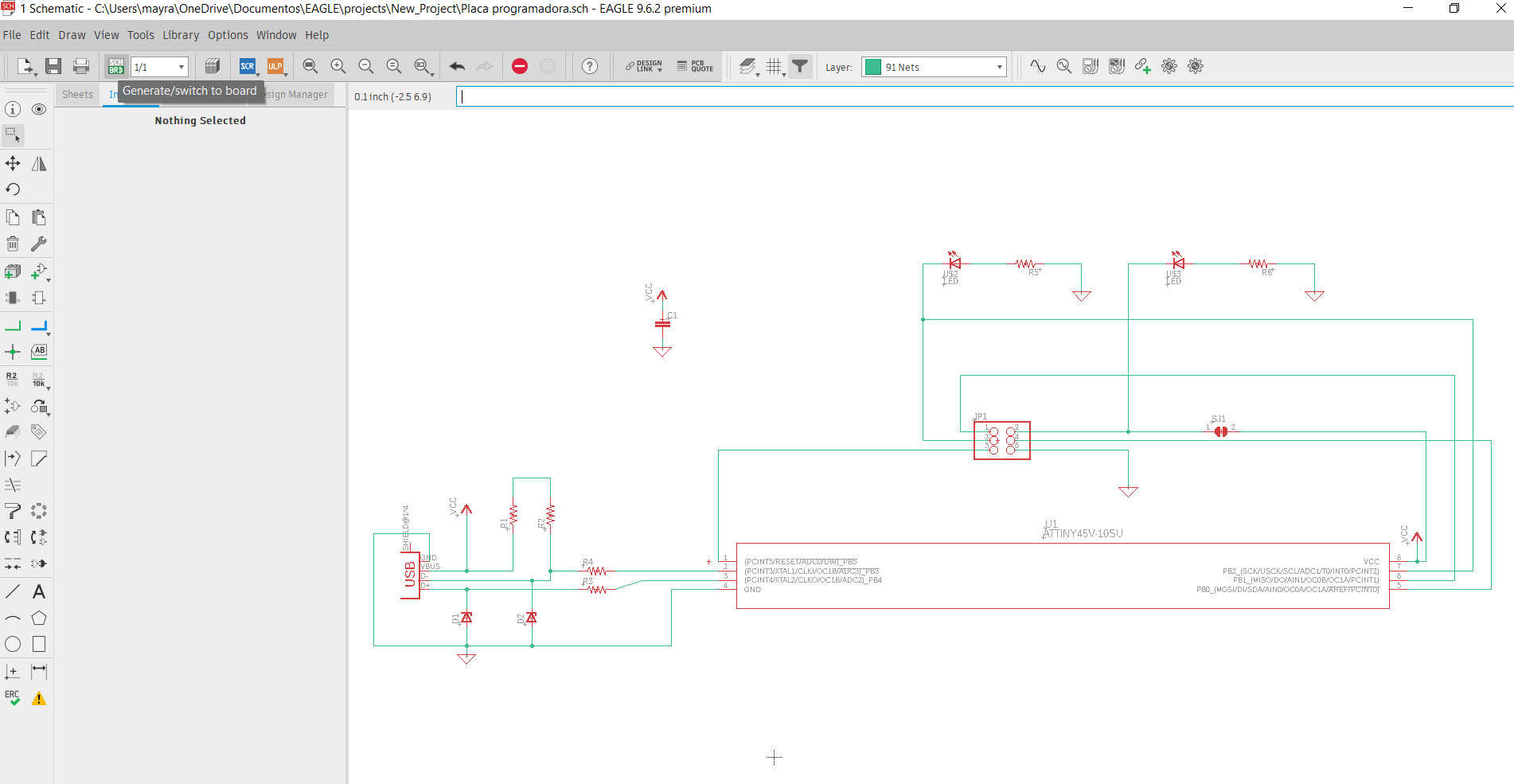
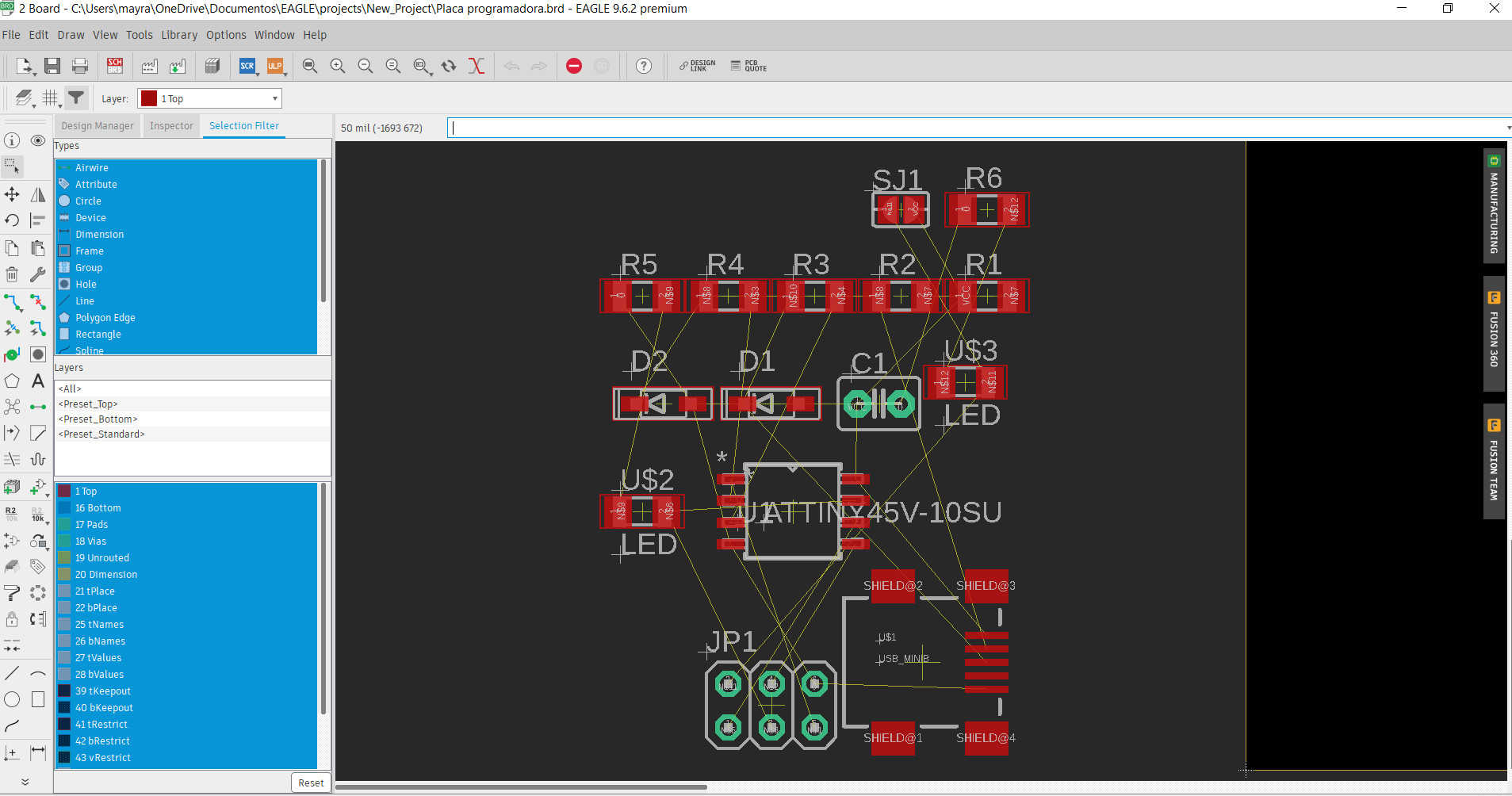
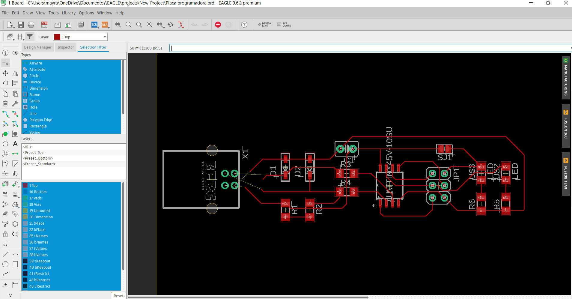
- The attempts were not the best, it took us many trials to generate the files and try to mill them but none were successful. We even tried in EAGLE to be able to export it in black and white image but we couldn't figure it out.


Eagle


Eagle


Eagle


Eagle


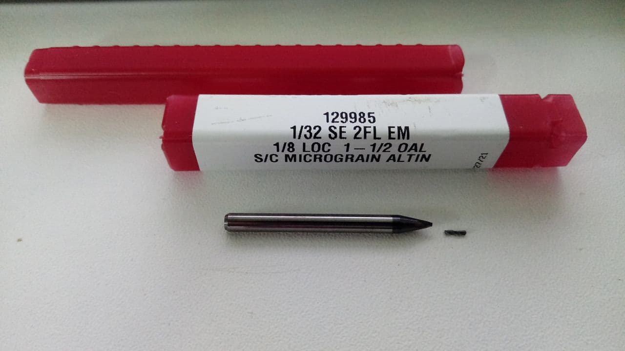
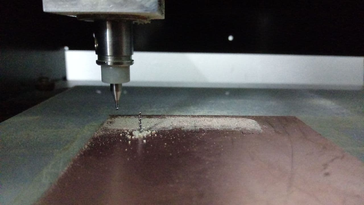
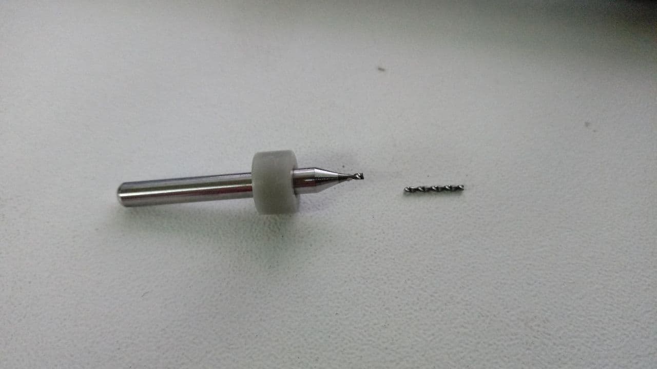
Broken milling cutter


Broken milling cutter


Broken milling cutter


Other milling cutter


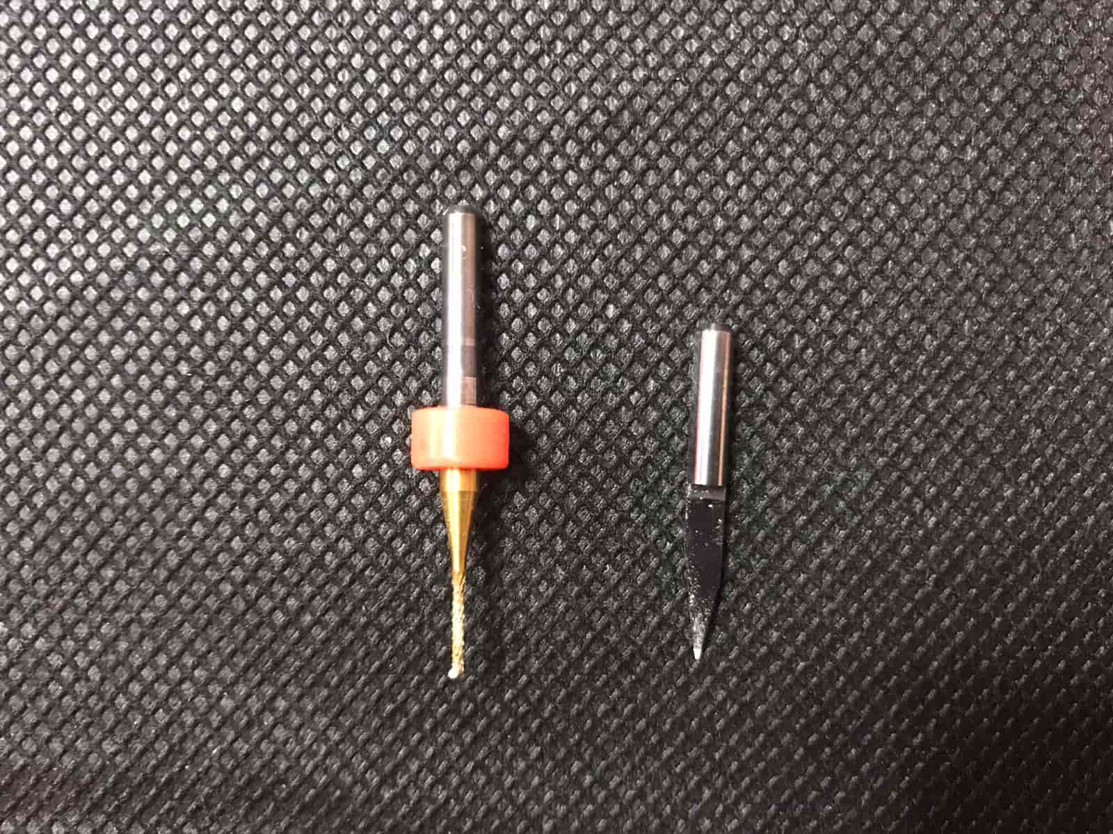
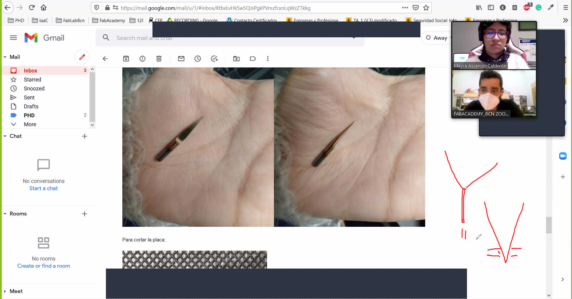
- After all these explorations we received advice from Eduardo Chamorro to understand the problem of our attempts, all the details such as the position of the milling cutter, the sacrificial bed, the calibration of the Z axis, etc, are very important, we believed that anyway the machine has been very beaten and outdated despite the repairs we made so we desisted from using it to not waste more time than we had already lost.


Zoom


Zoom


Zoom


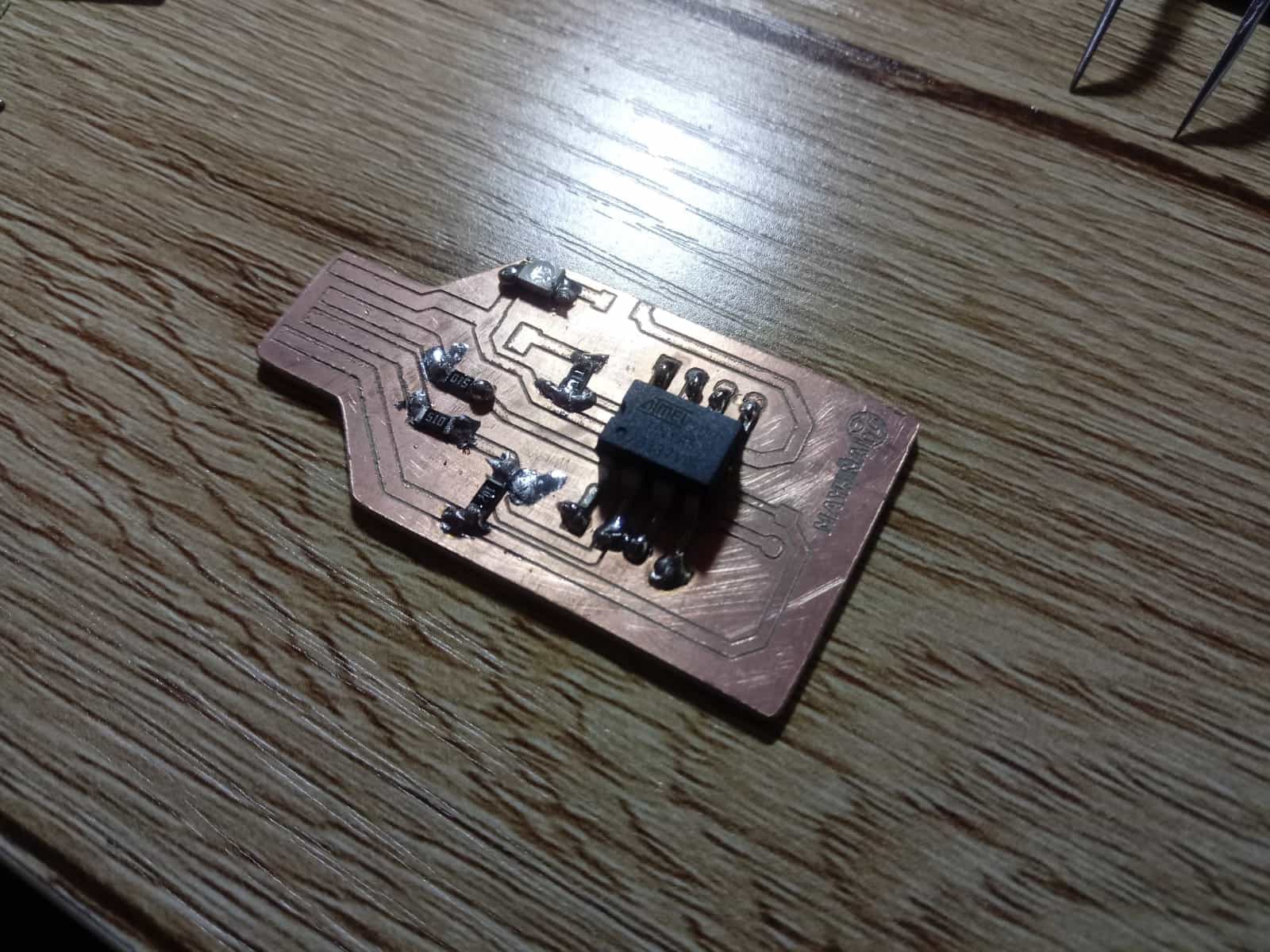
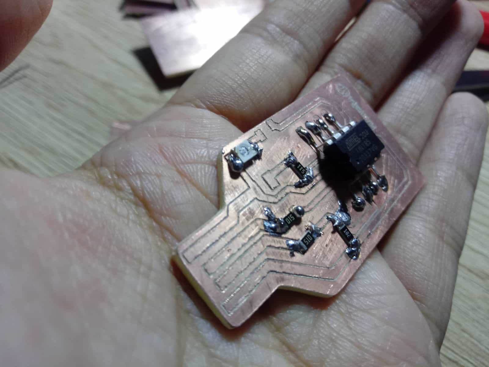
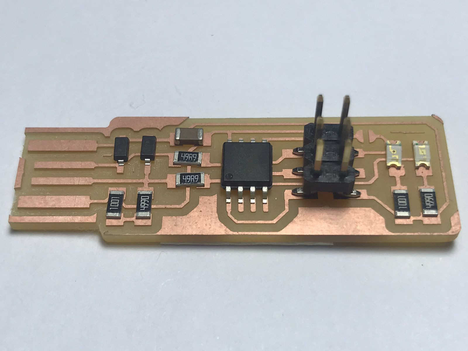
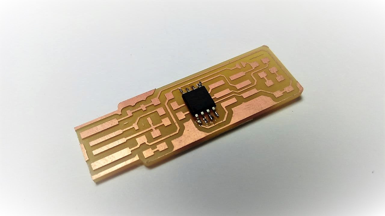
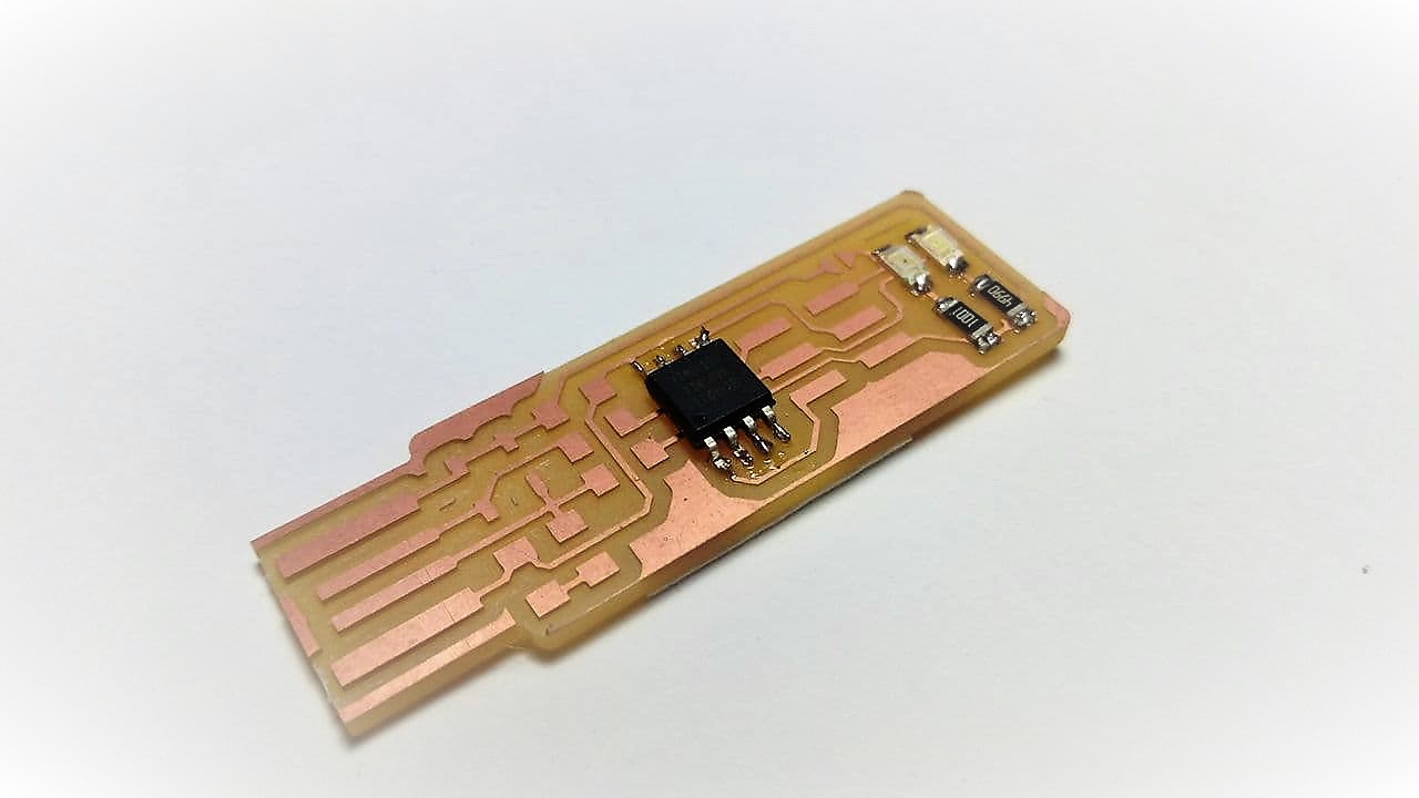
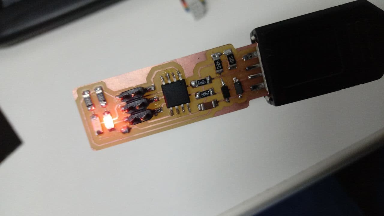
Fab ISP ready


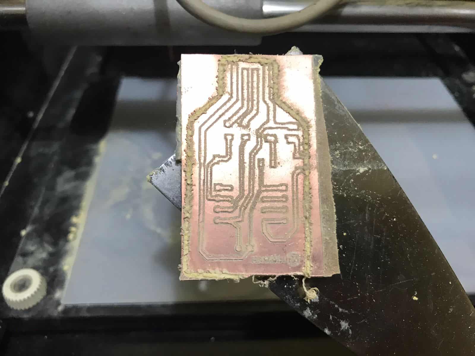
- Thanks to the instructors at Fab Lab ESAN we were able to understand the difference between their machine and ours, they also had a Roland Modela MDX 20 but in a much better condition. We finally got our board manufactured, here are some pictures of the process.


Zoom


Zoom


Zoom


Zoom


- Next step is to solder our components, thanks to Fab Lab Barcelona we got all the necessary ones, both Stef and I followed the references of other students who also made this programming board as Adrian's page and Bryan's page .


Milled plate


Components


Components


Welding kit


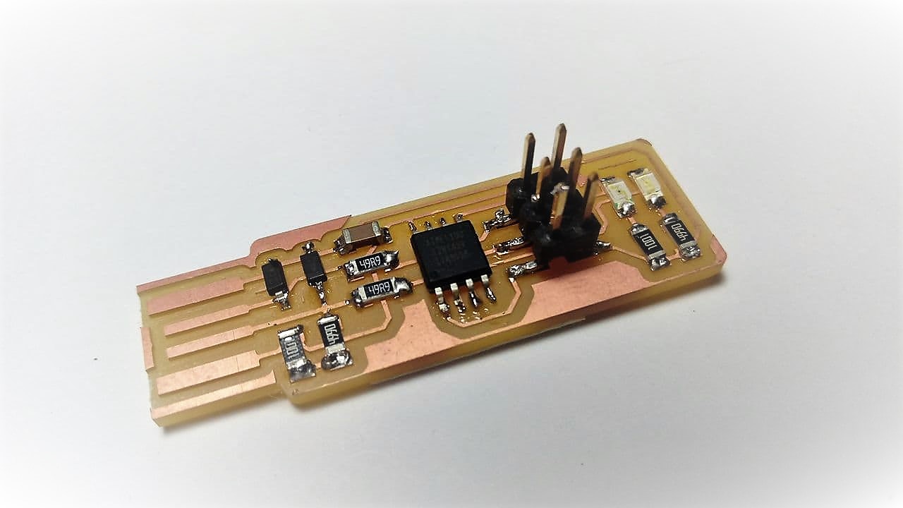
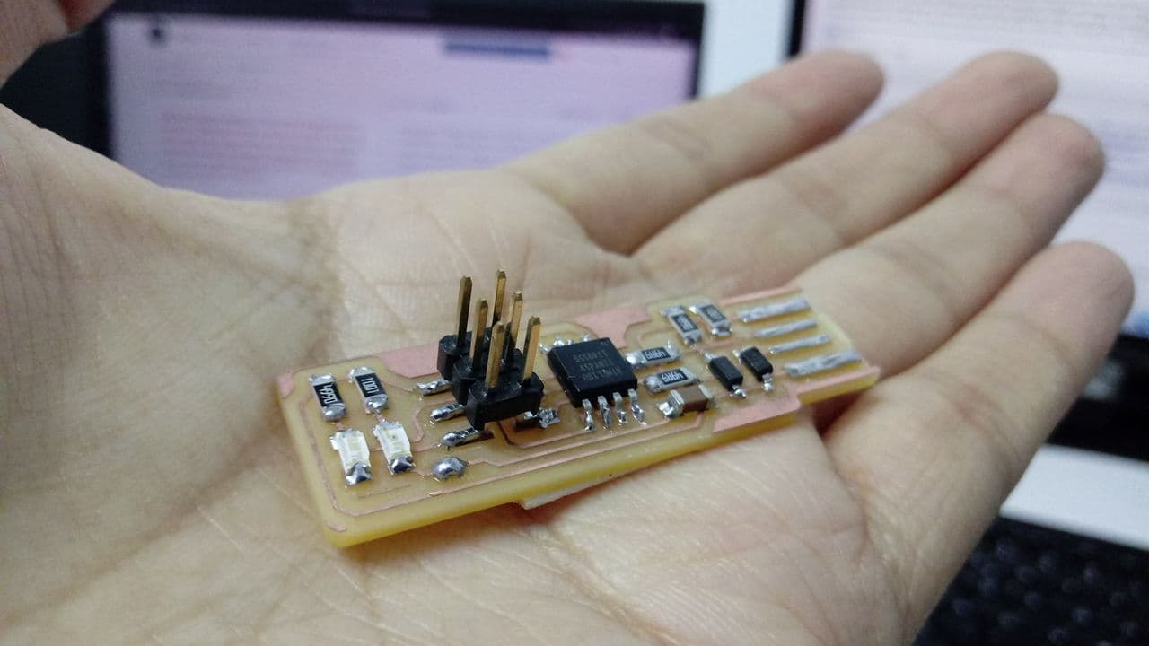
- My soldering process has improved a lot, unlike the first weeks now I use less tin than before, without a doubt it is important to practice, I recommend that you use other alternative plates to start to get familiar and then solder the important plate, I still lack practice but I have improved, here I show you my results.


Practice 1


Practice 2


First the Attiny 45


Then resistors and leds


Ready!


❀️


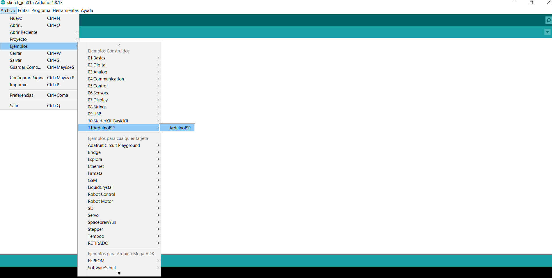
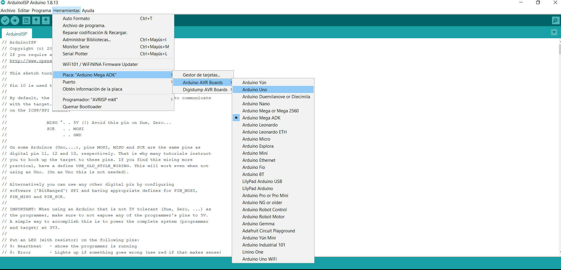
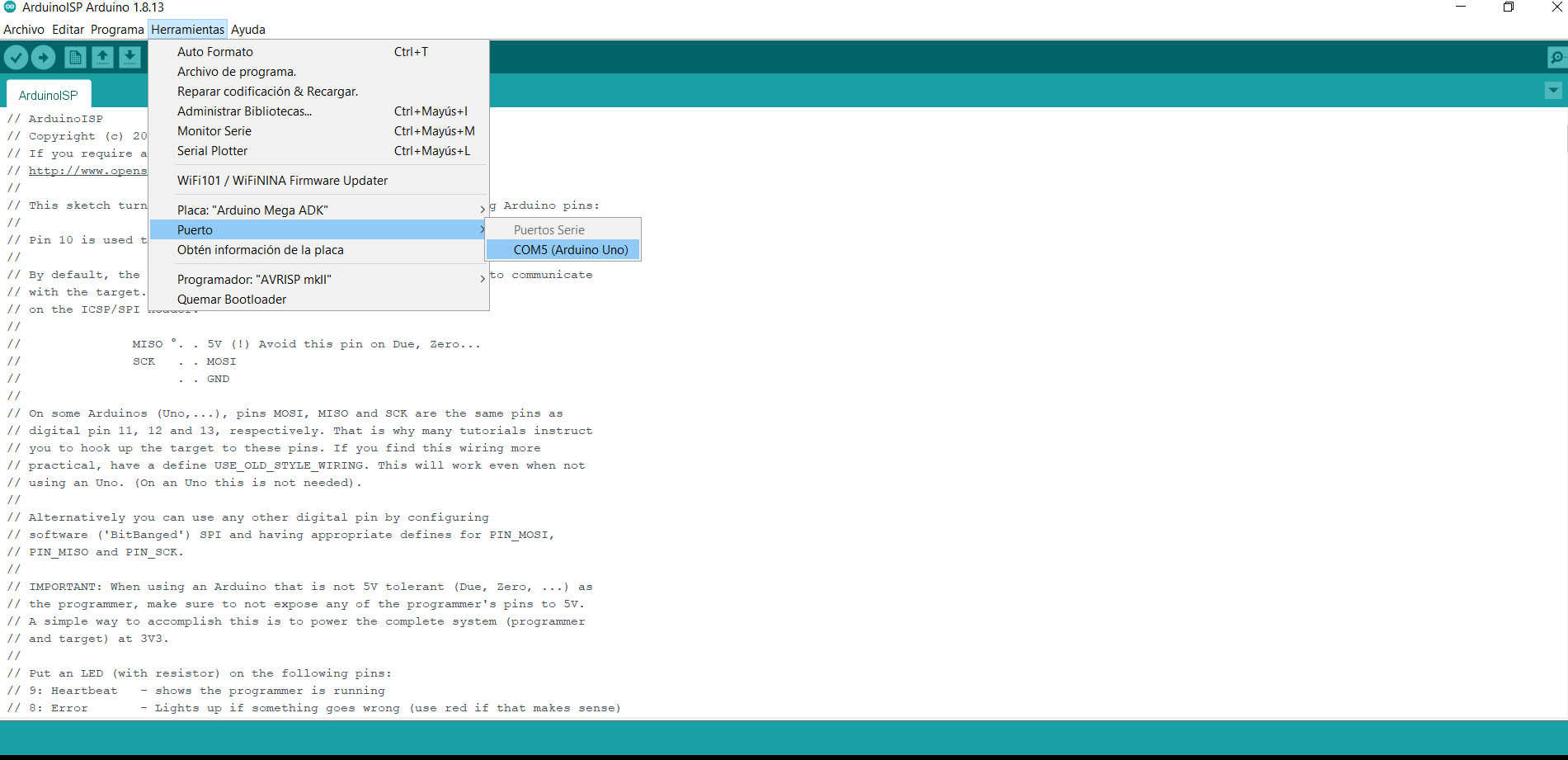
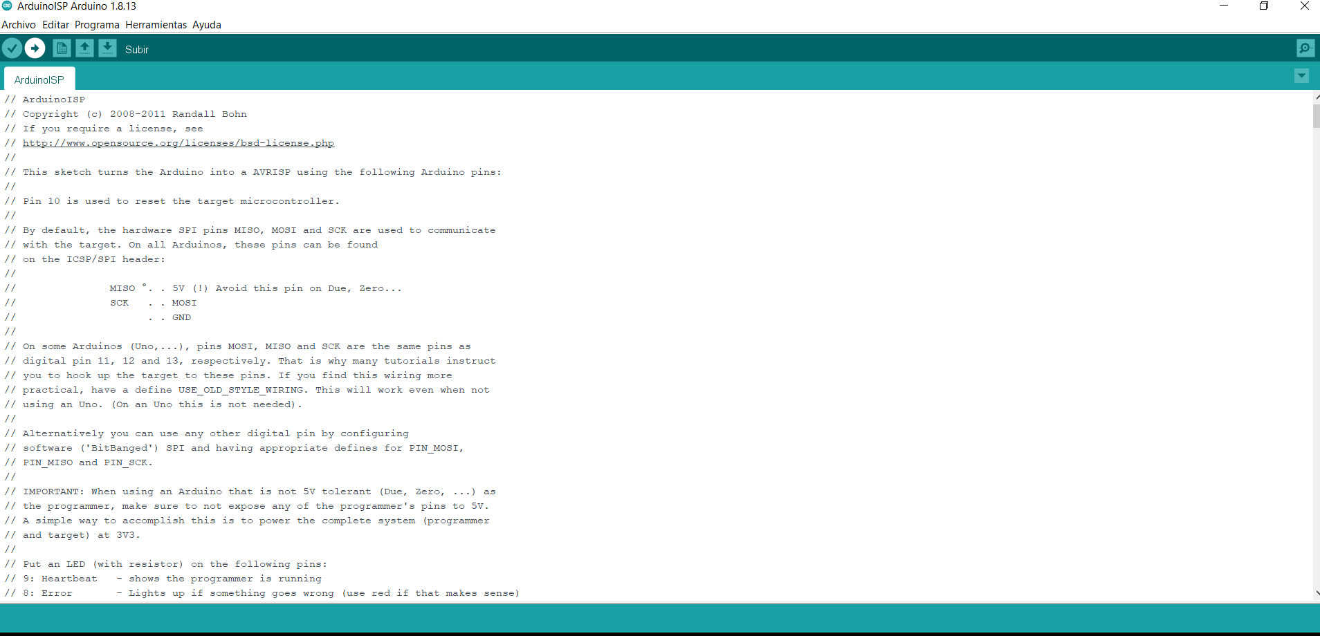
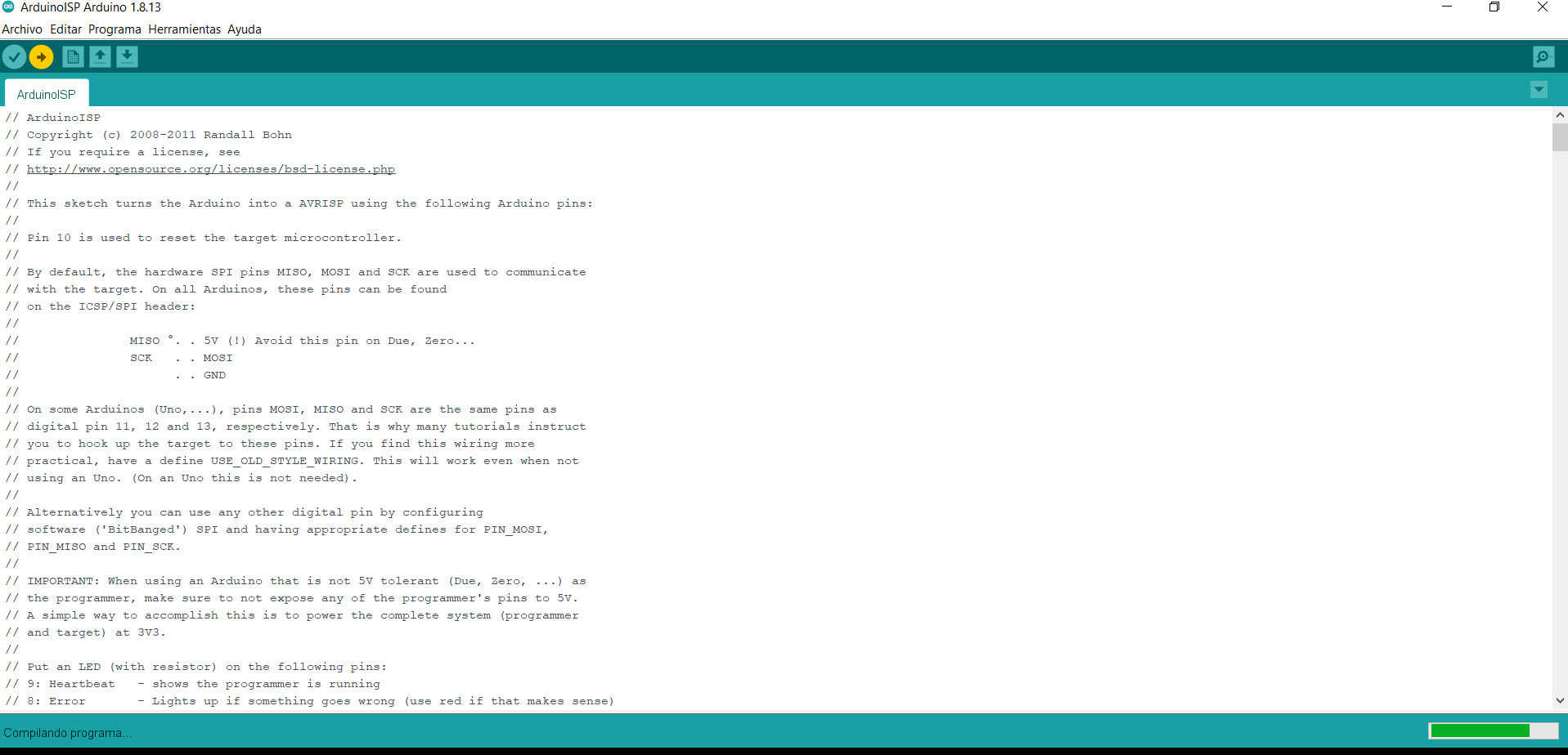
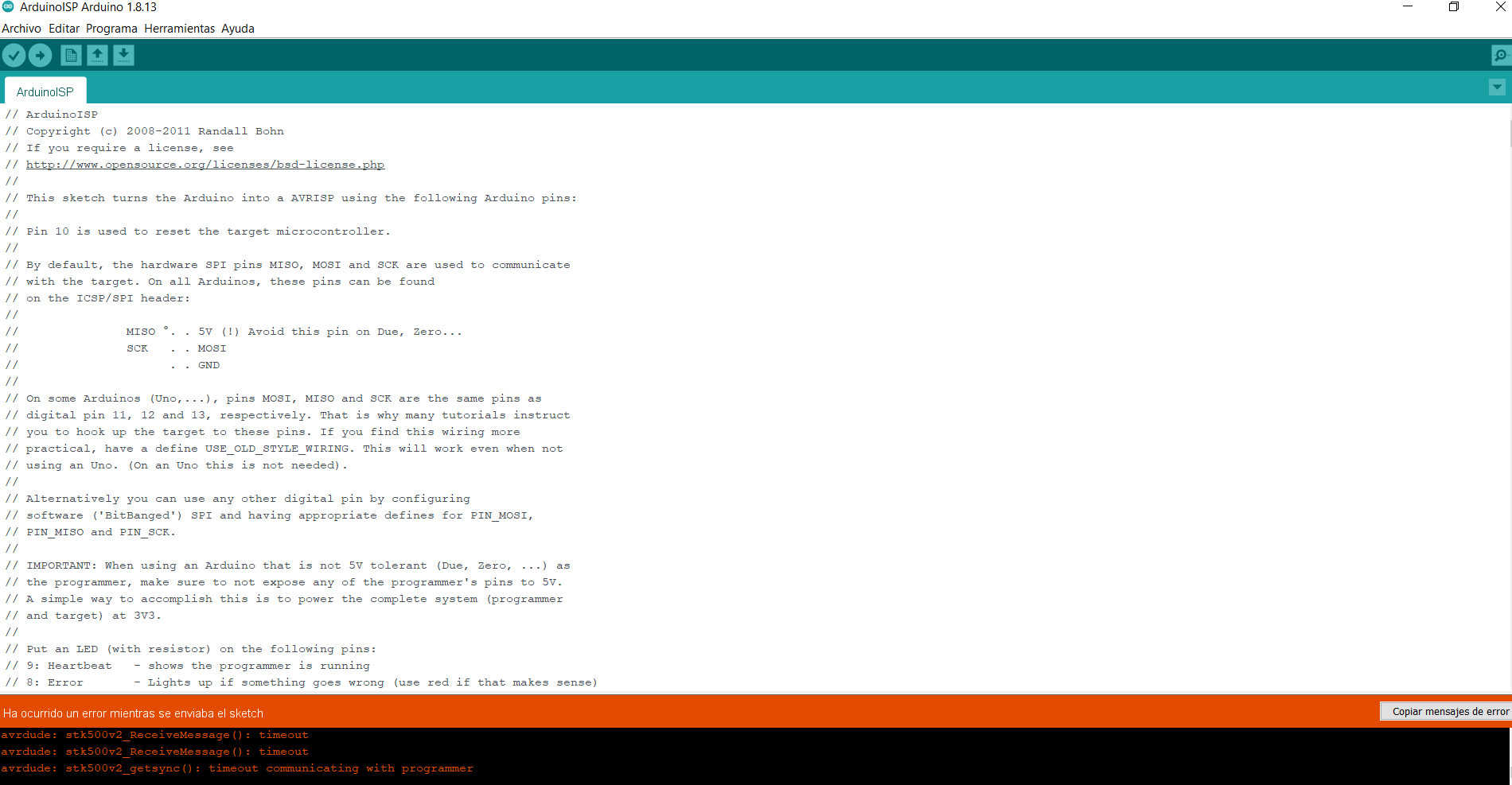
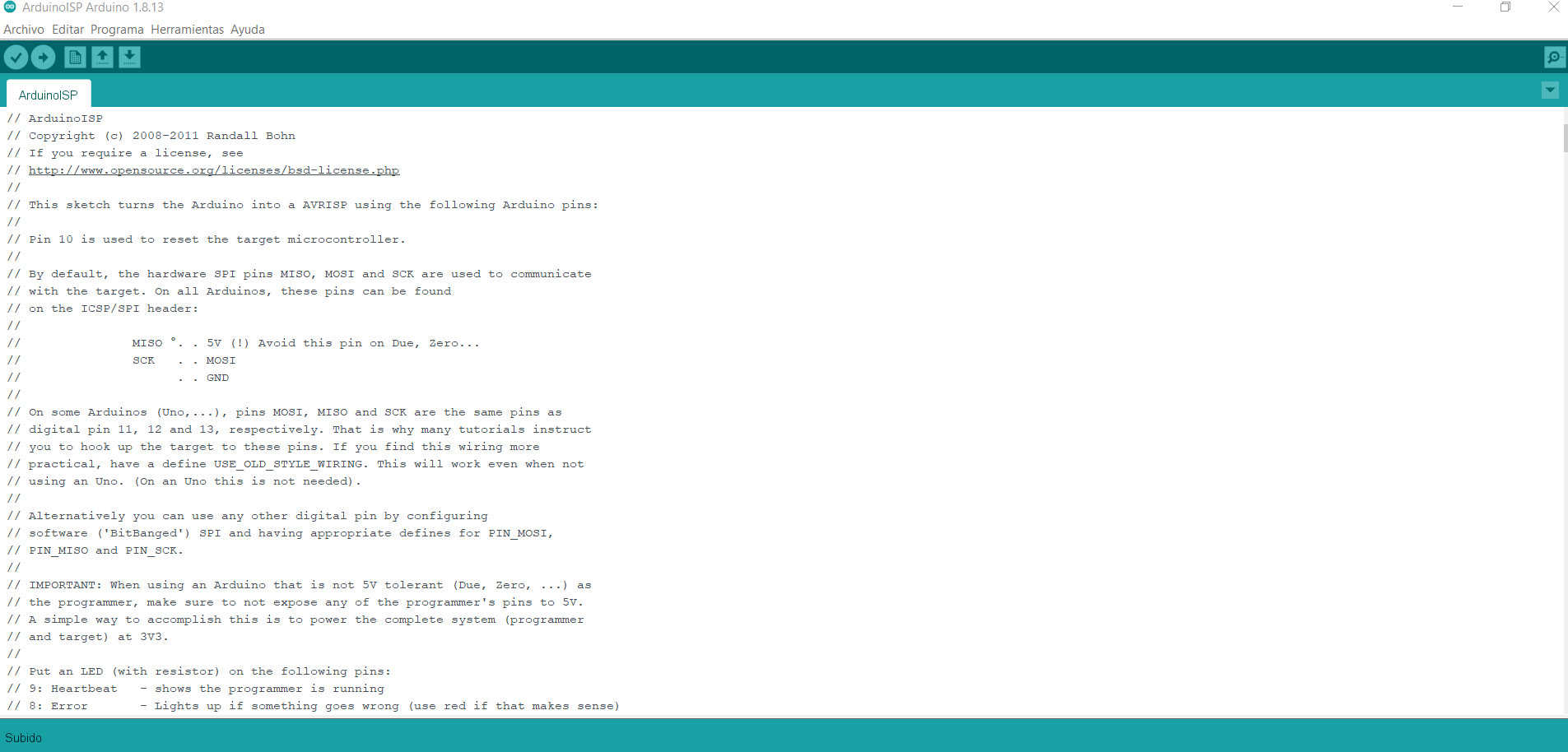
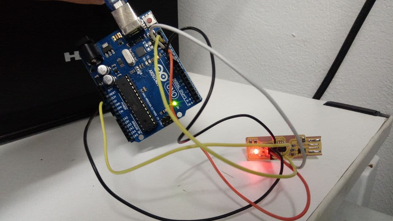
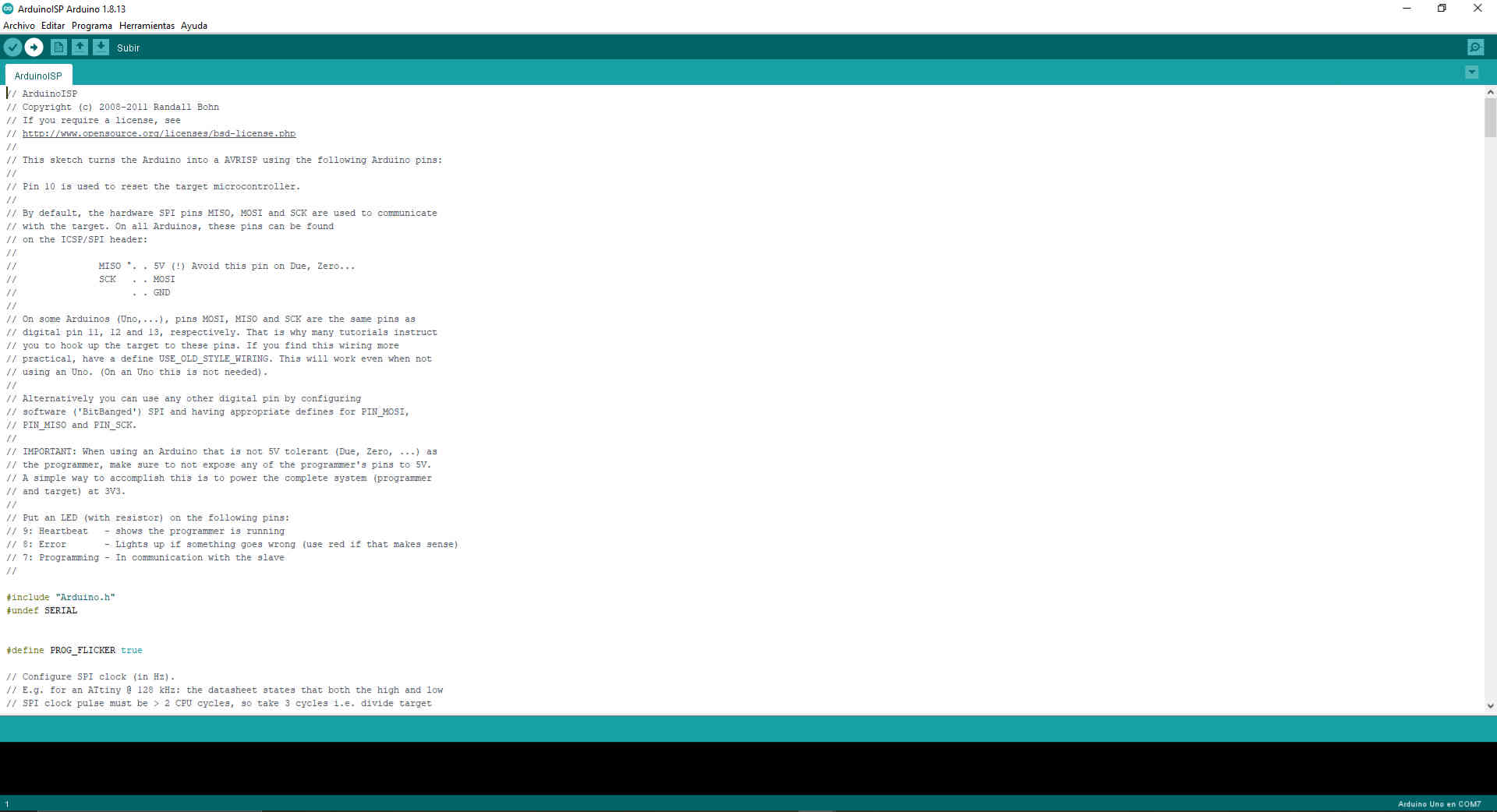
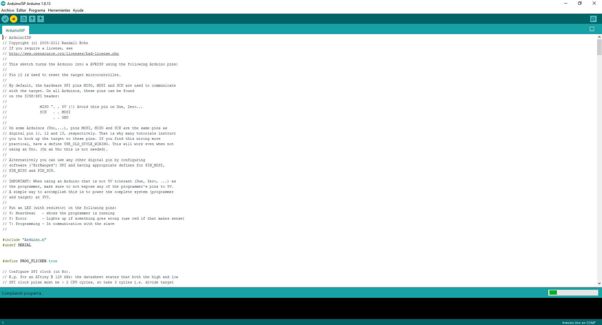
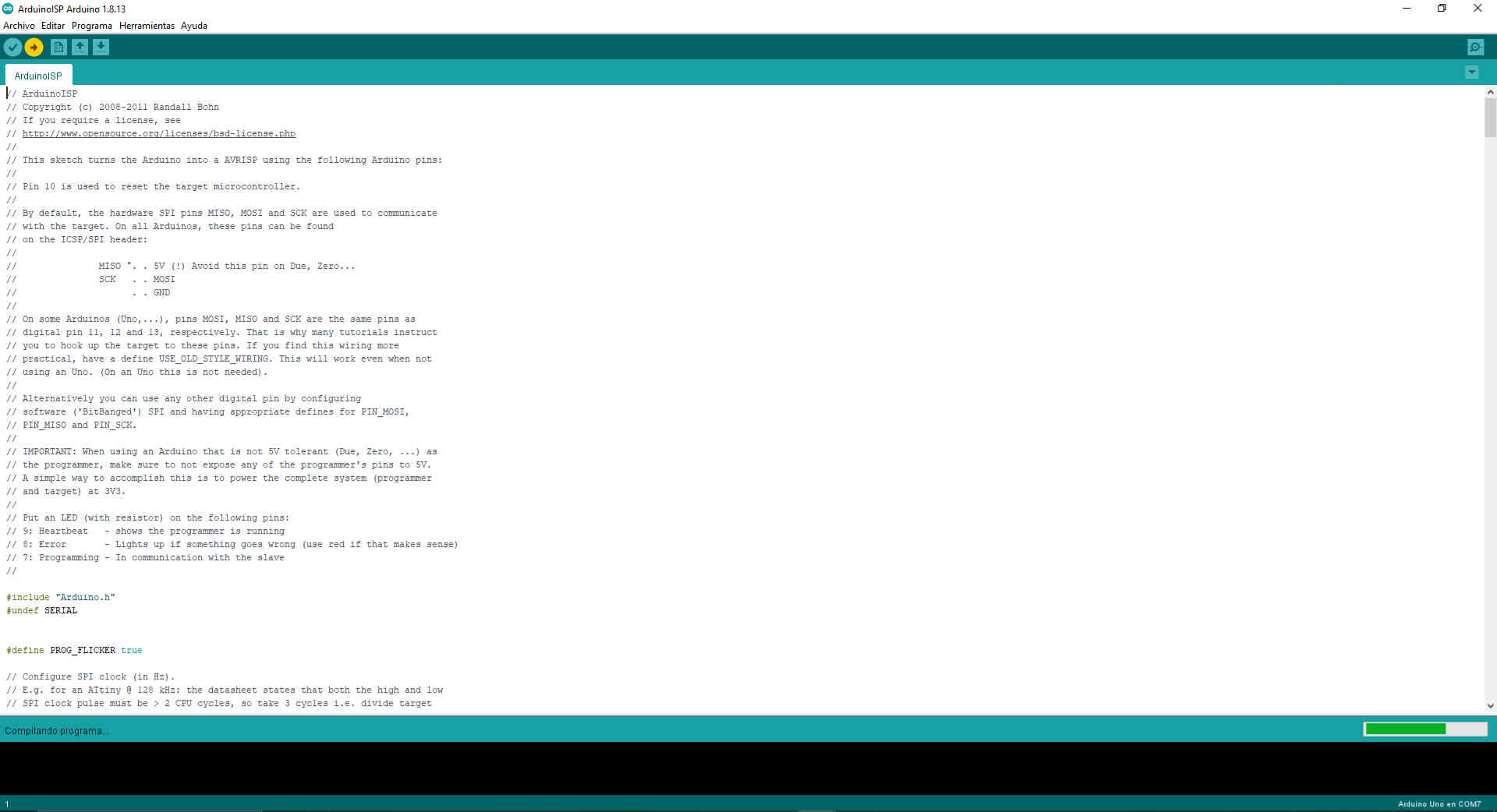
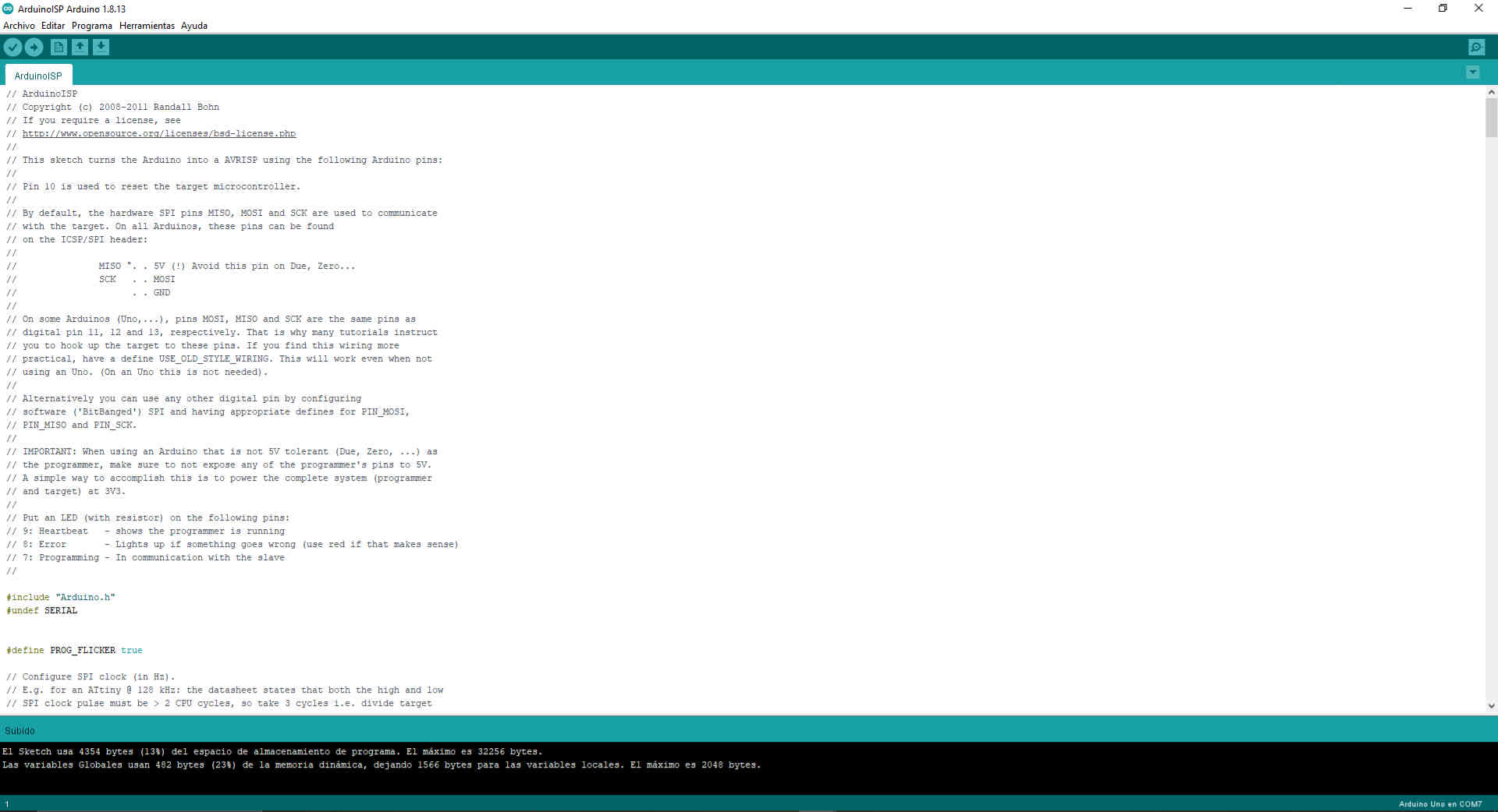
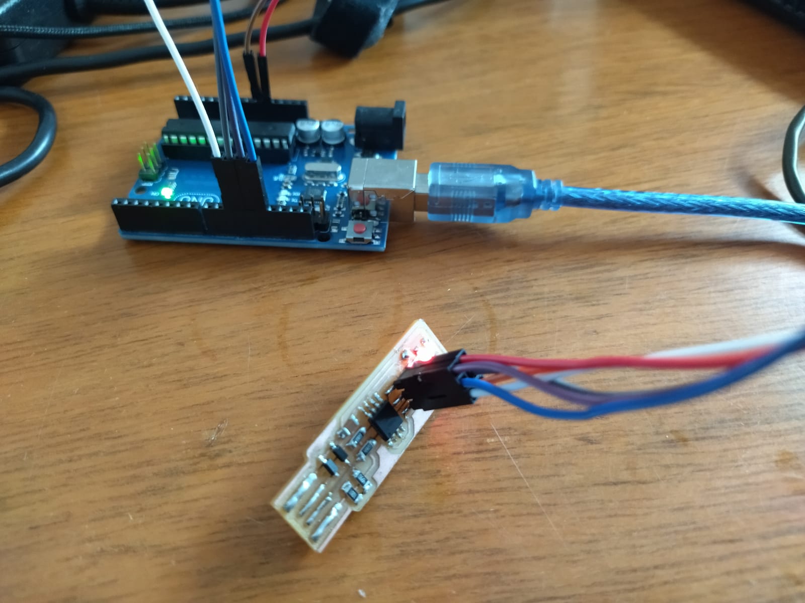
- After finishing the soldering we did some tests to test the board, it was a bit confusing to do this step since we did not have an alternate board. We did the exercise with Windows and an Arduino UNO, below I share some steps.


Arduino UNO


Arduino ISP


Select Arduino UNO


Port


Compile


Compiling program


Failed load


Second successful attempt


- As a next step I had two sources with which I could guide me better, at this stage you must follow some references according to the resources you have so in our case we made a mix on the recommendation of my instructor. The first one is by Xavier Klein and the second one by Jakob Nilsson , both have particular steps because they use the same Fab ISP with different connections. Below I share my tests.


Direct connection


Connected to the arduino one


New season


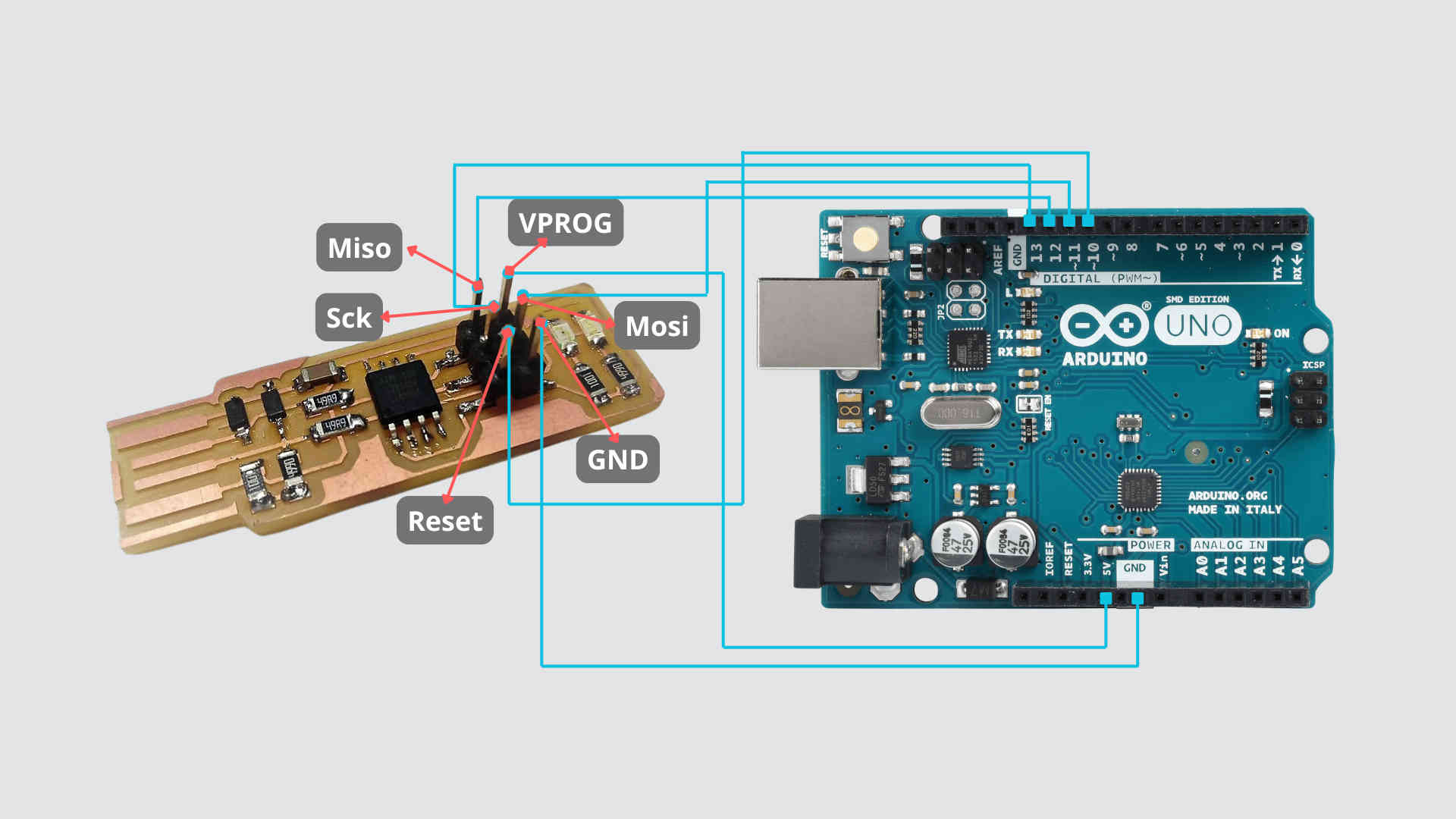
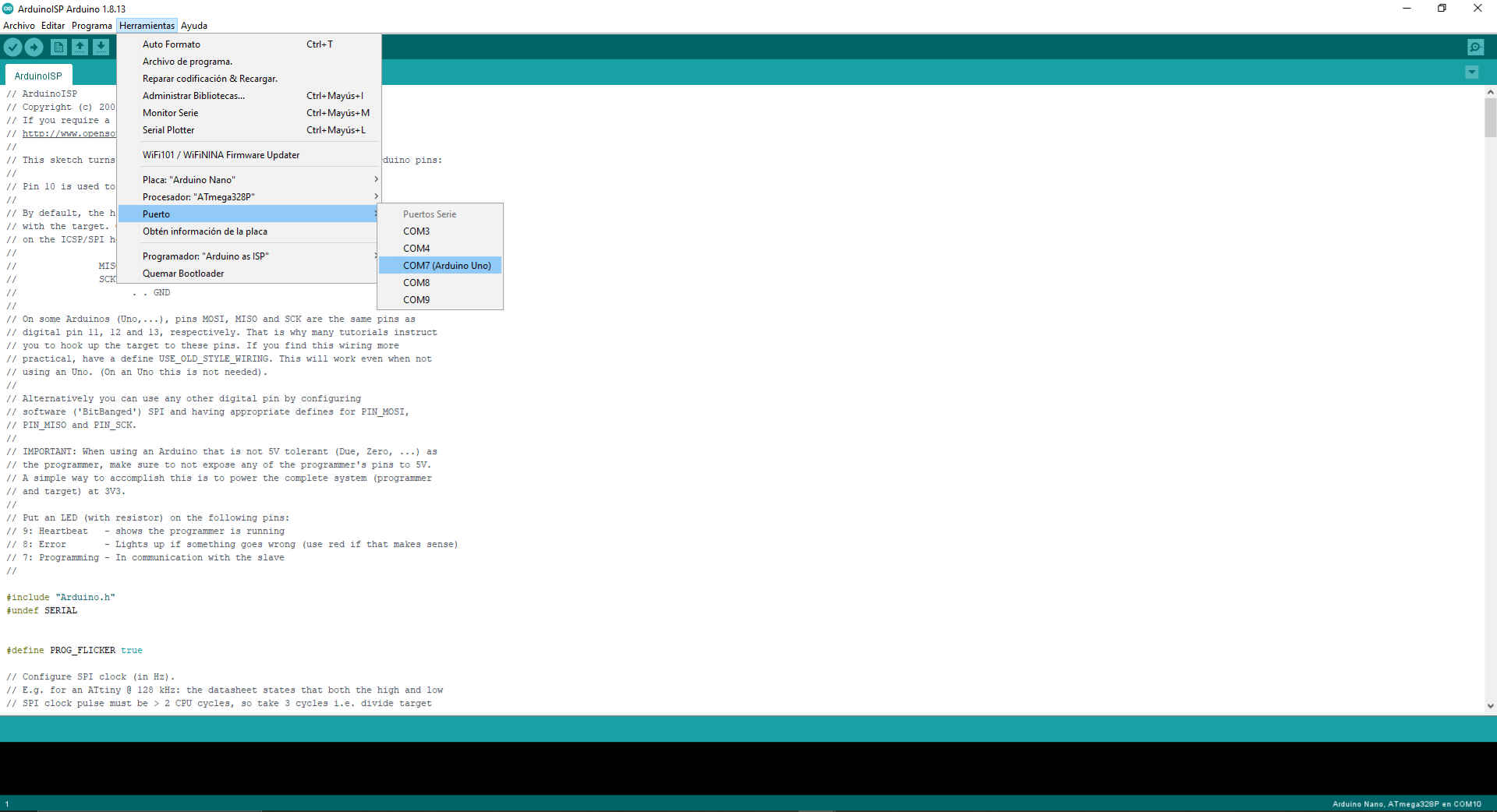
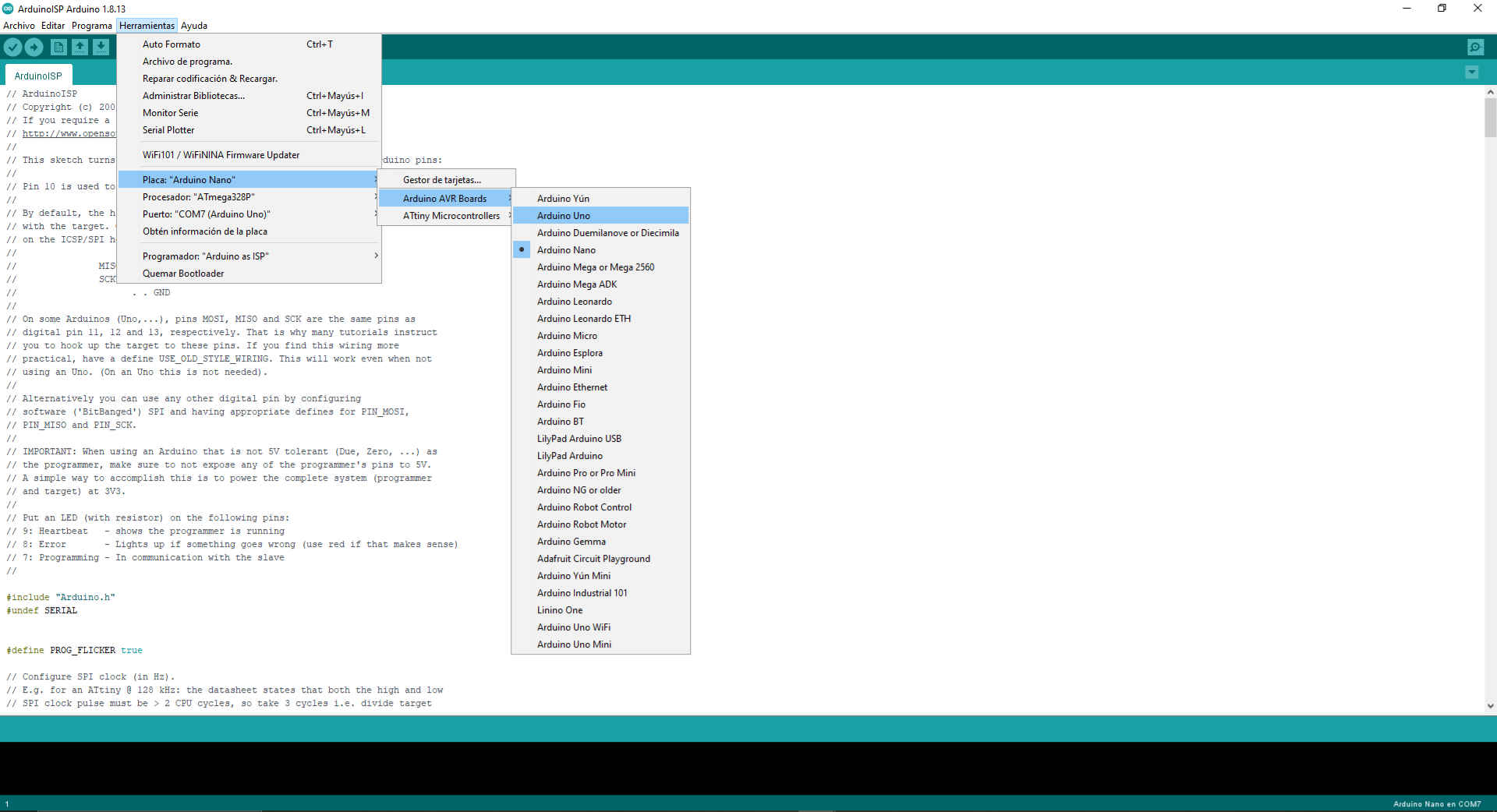
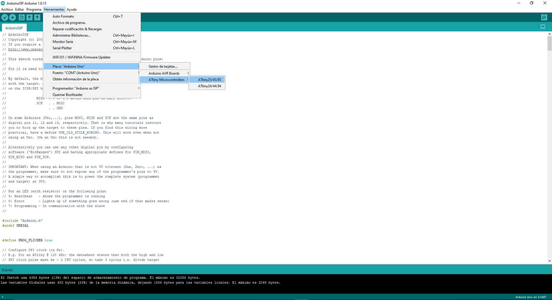
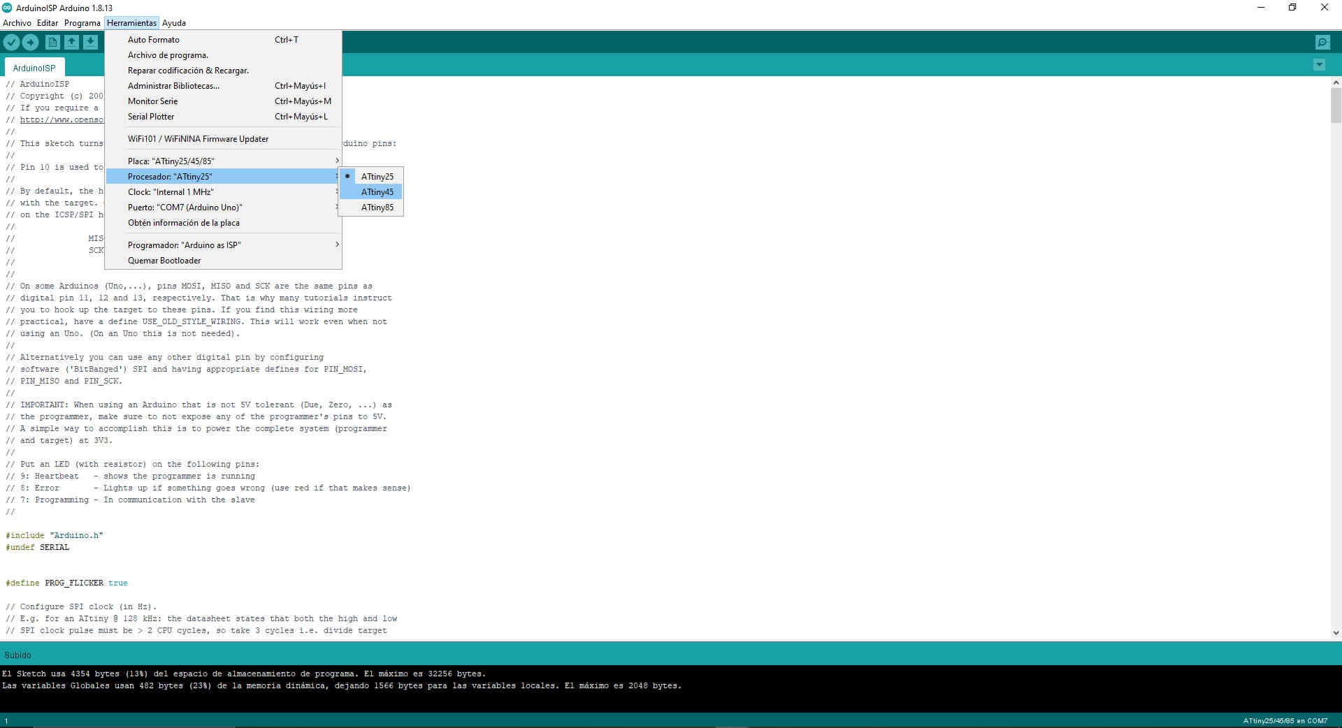
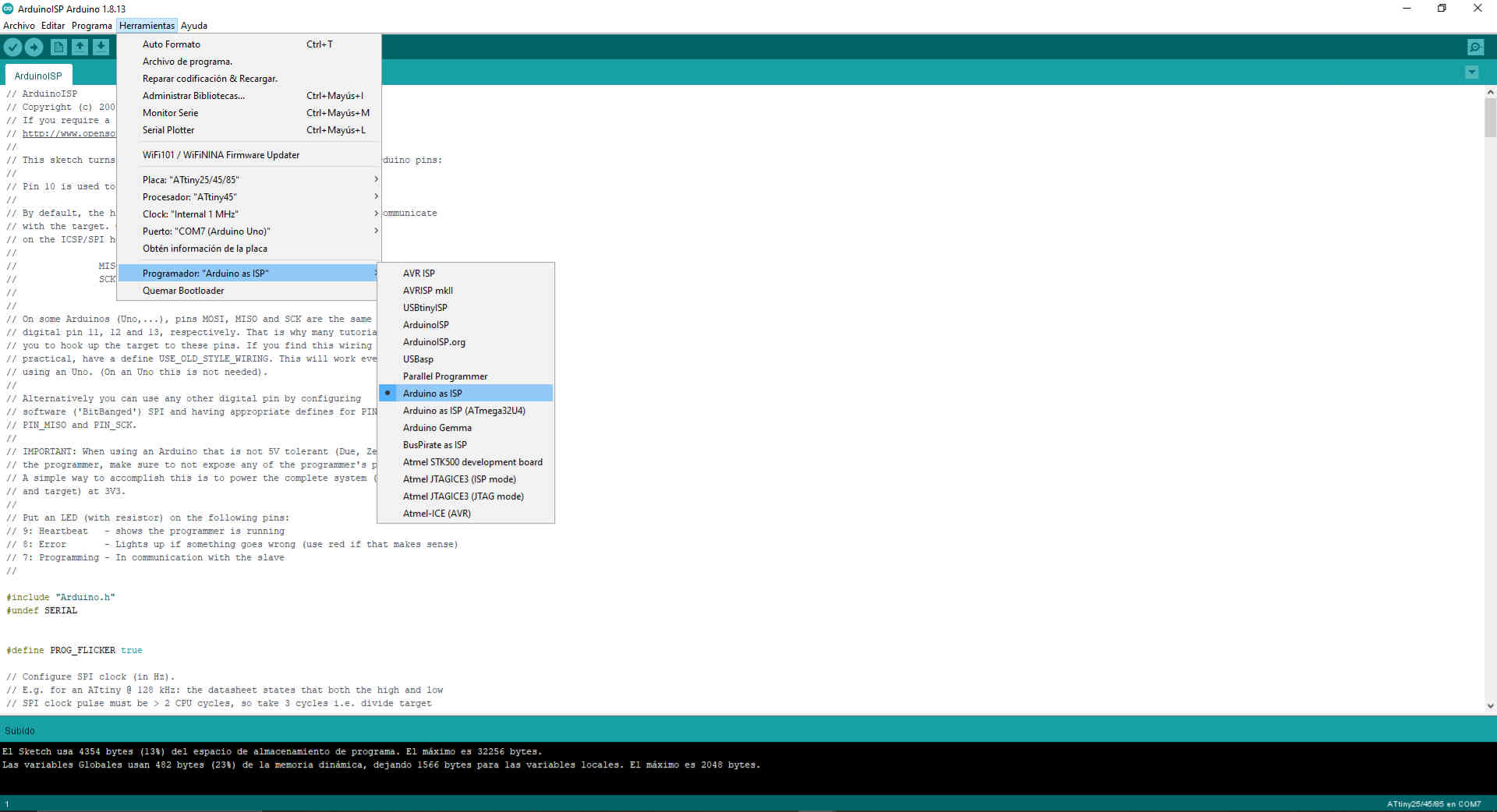
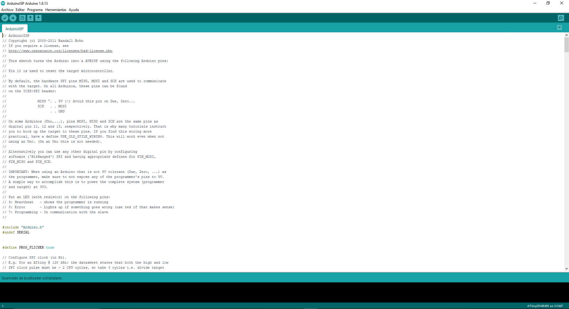
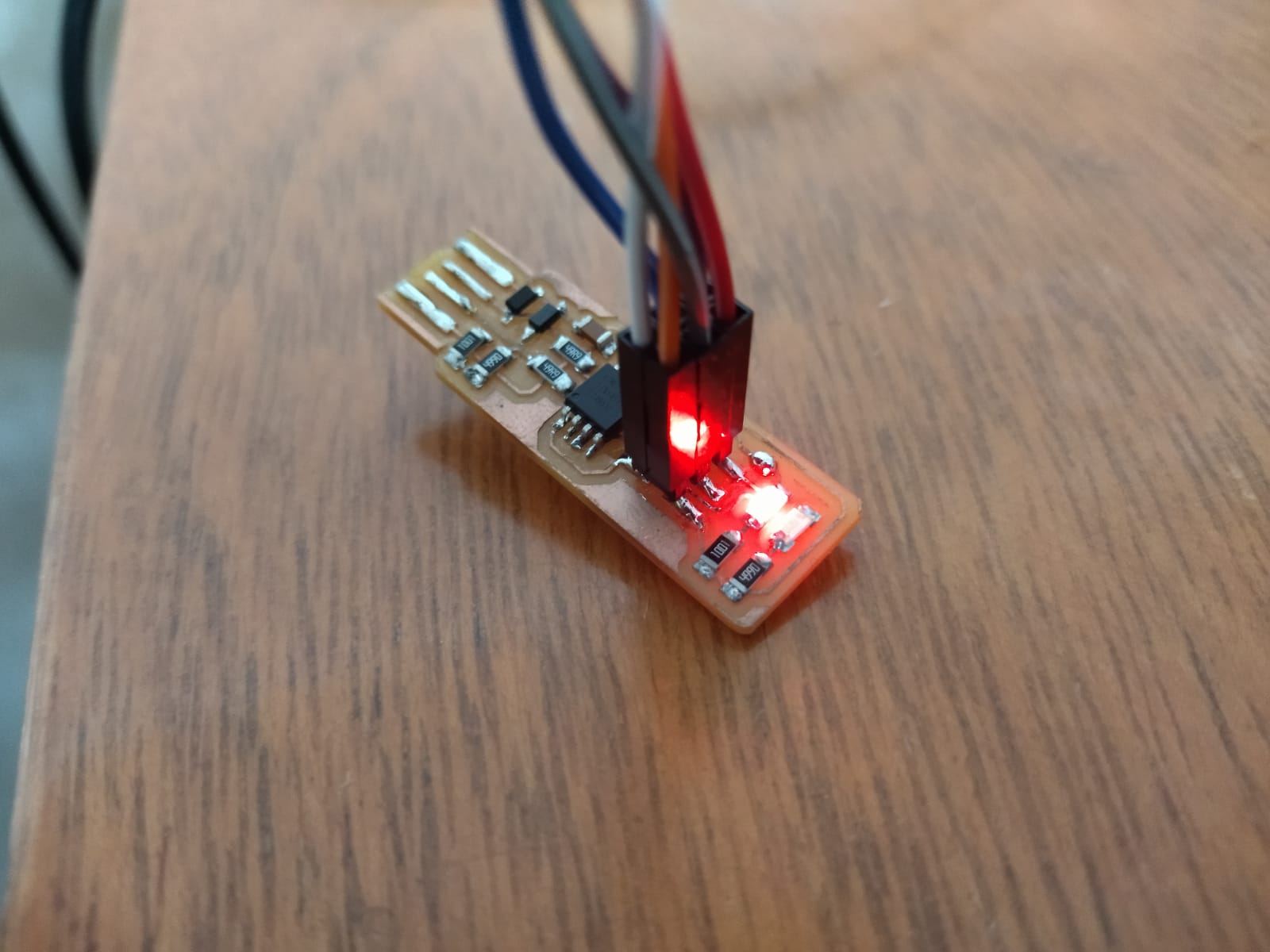
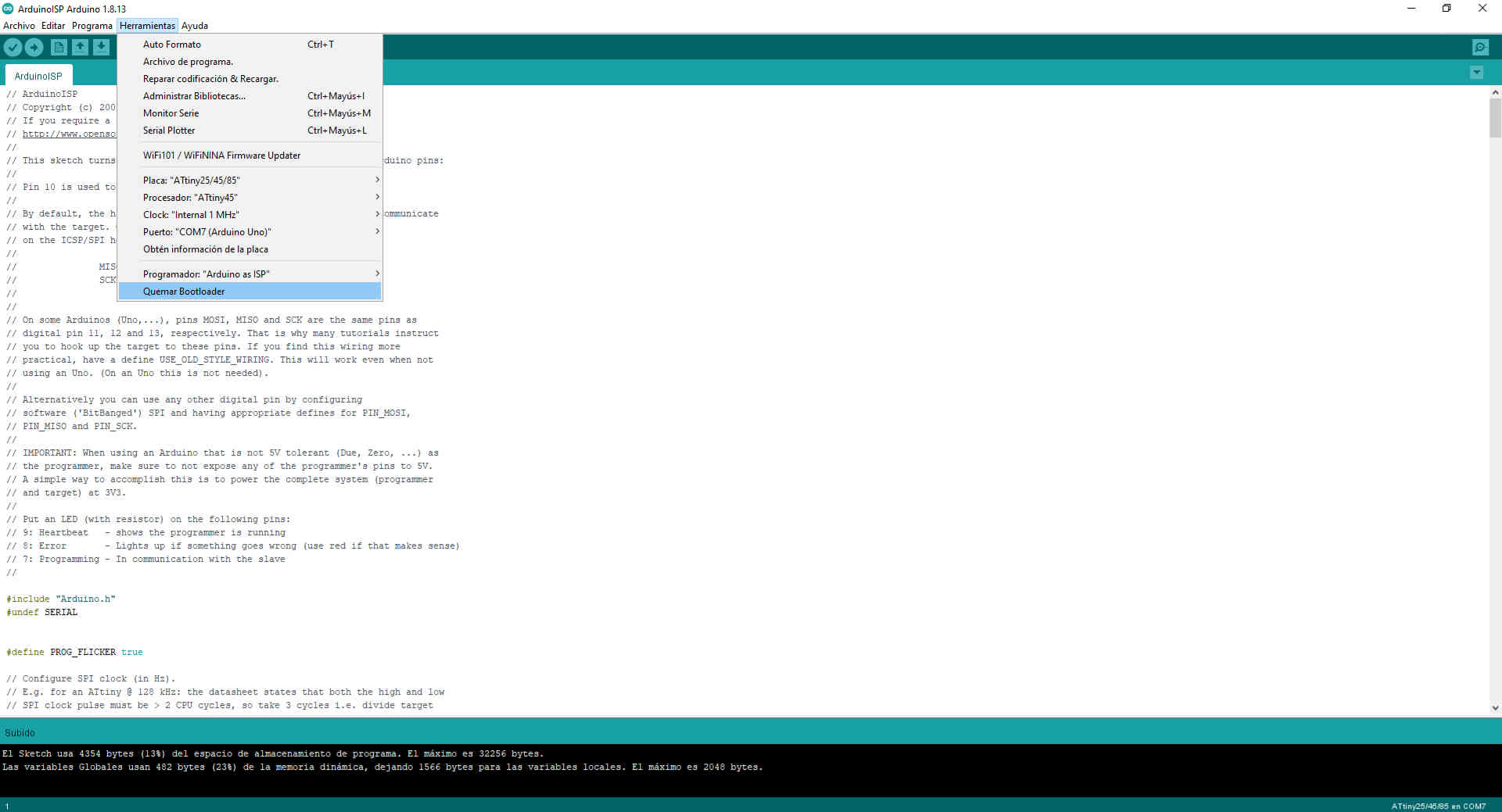
- It has been a complicated path, but finally we have achieved it, this time I have been able to program my Fab ISP. 😍 It is important to know that to achieve all these steps we have had a long journey of research and many tests. Below I share a little step by step of my experience.


Diagram


Arduino IDE


Choose Arduino ISP in examples


Choose the port


Choose the plate


Arduino ISP code


Compile the program


Compile the program


Uploaded program


Choose the microcontroller


Choose the processor


Choose the right programmer


Burn bootloader


Bootloader burn completed


Fab ISP ready


Fab ISP ready


Download the files here


Contour trimming - Fab ISP
Traces - Fab ISP