To begin to operate a machine you have to understand how it works, its features, its parts and especially its limits, I had already handled a laser cutter before but I had never stopped to understand its operating system. This space has allowed me to research and learn more about the concepts of cutting and also explore its capabilities. This system is very interesting because being a precision work it helps a lot to the quality of the cuts and of course with a speed that hardly a human being could replace.
Next I will share some summarized graphics about how a laser cutter works, thanks to the Fab Lat team we had a special session with one of the specialists in Trotec machines, his name is Luis Flores and here we know him as LEFO, we met online with him to have more information and suggestions from him, thank you very much master! 😃
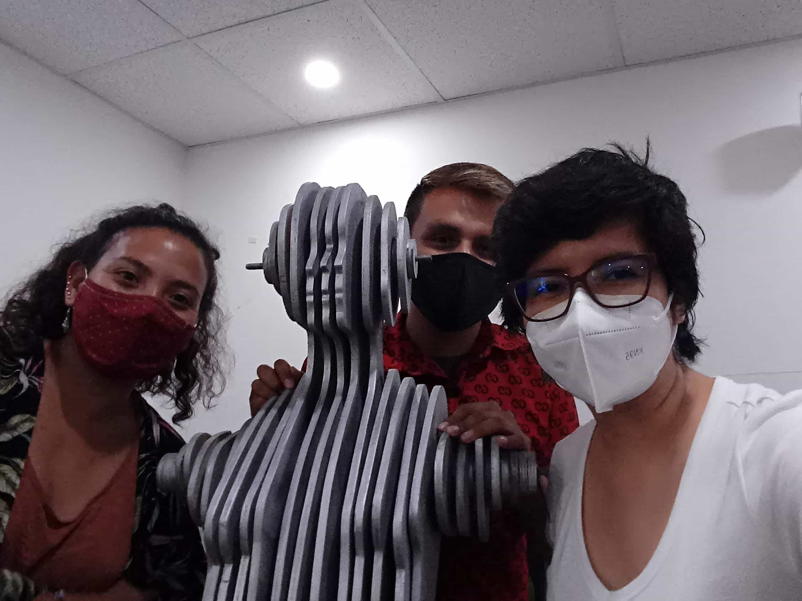
Reencounter at Fab Lab Lima with Stefany and Hayashi.
General concepts
-
Laser: A laser (LASER, light amplification by stimulated emission of radiation) is a device that uses an effect of quantum mechanics, induced or stimulated emission, to generate a spatially and temporally coherent beam of light.
-
Focus: In geometrical optics a focus is the point where the light rays originating from a point on the observed object converge.
-
Vector: In mathematics and physics, a vector is a mathematical entity such as a line or a plane. A vector is represented by a line segment, oriented in three-dimensional Euclidean space.
-
DXF: DXF (Drawing Exchange Format) is a file format for computer-aided design drawings, created primarily to enable interoperability between DWG files, used by AutoCAD, and other programs on the market.
-
Power: In physics, power (symbol P) is the amount of work done per unit time.
-
Speed: Velocity is the vector physical quantity that relates the change of position (or displacement) to time.
-
Cutting: Laser cutting is a technique used to cut sheet metal parts characterized in that its energy source is a laser that concentrates light on the work surface.
-
Engraving: Engraving is an artistic discipline in which the artist uses different printing techniques, which have in common the drawing of an image on a rigid surface, called matrix, leaving a print that later will house ink and will be transferred by pressure to another surface such as paper or canvas, which allows obtaining several reproductions of the prints.
-
Marking: "Laser marking" means marking or labeling parts and materials with a laser beam. In this respect, different procedures are differentiated, such as engraving, removal, discoloration, annealing and foaming. Each of these processes has its own advantages and disadvantages depending on the material and the desired result.
(Source: Wikipedia.com)
Graphic concepts
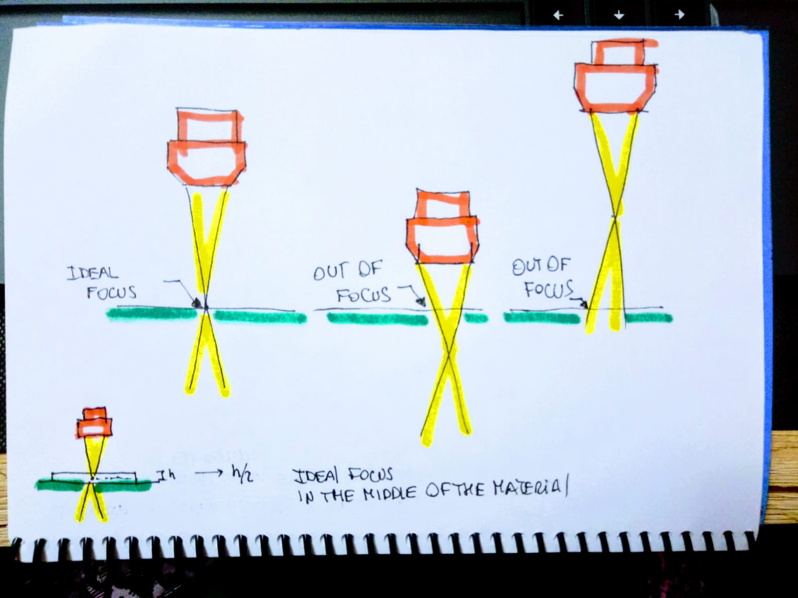
Position of the laser focus
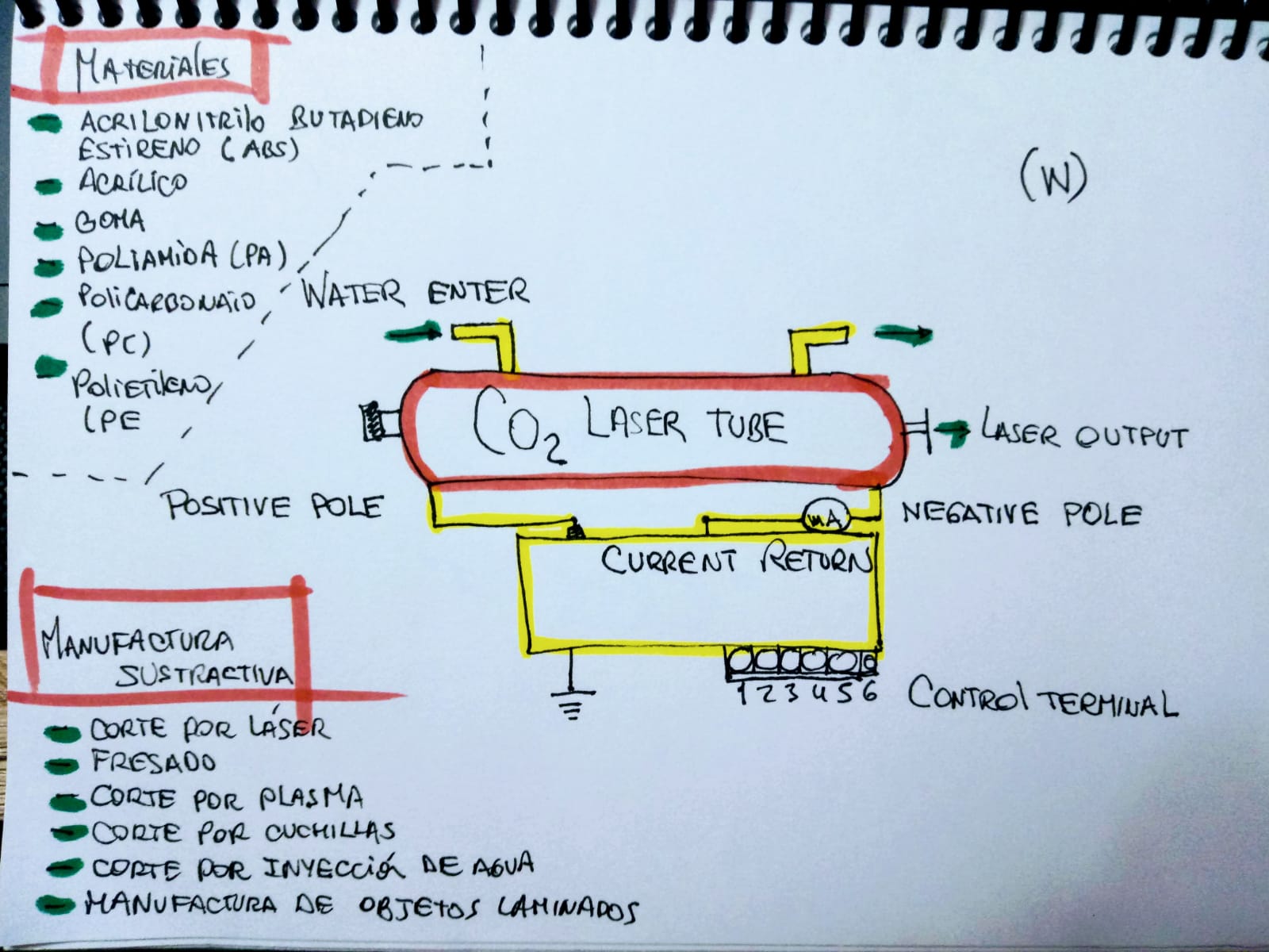
Laser tube process
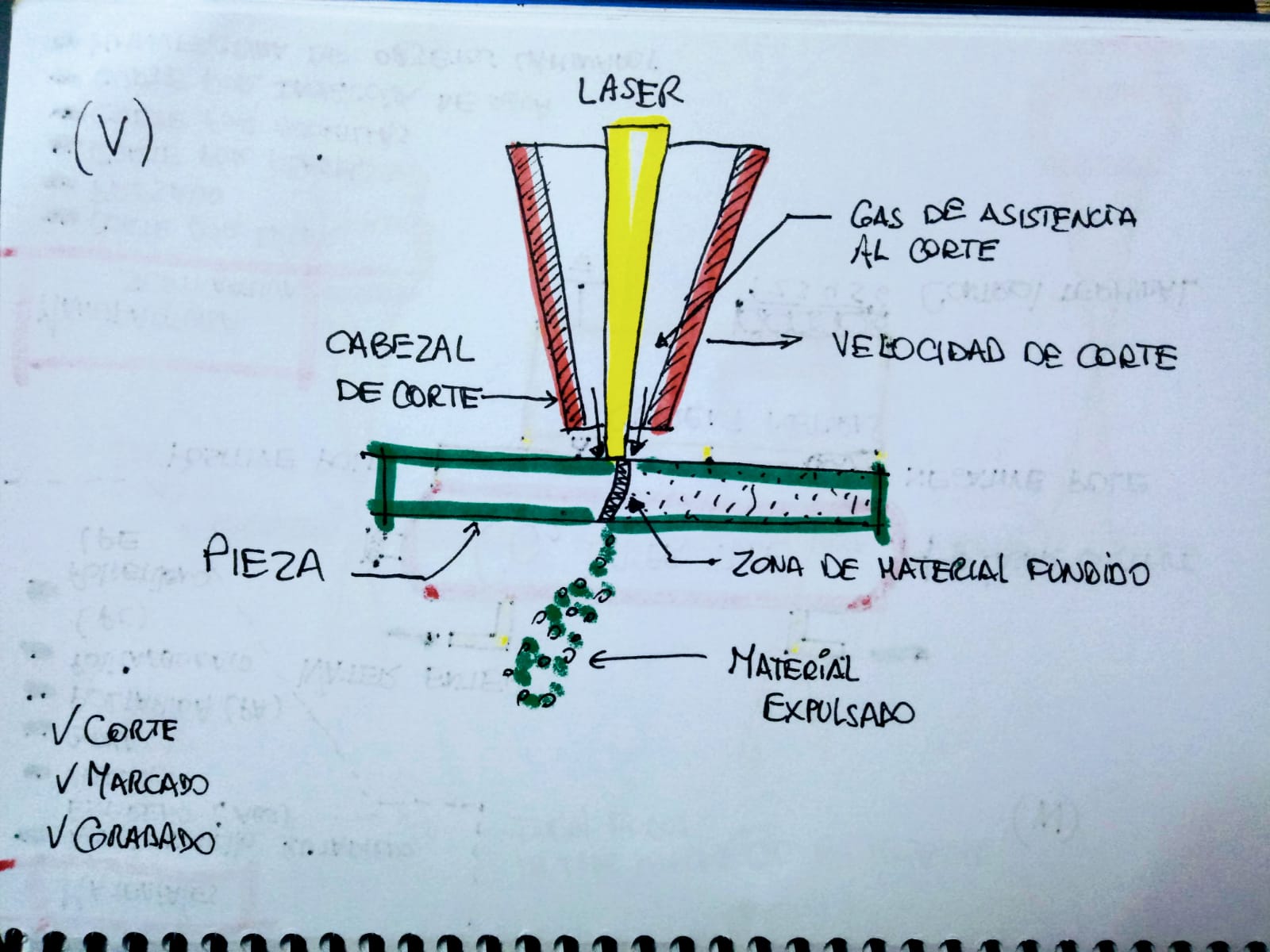
Detail of laser cutting
Laser Cutter
Steps to use the machine
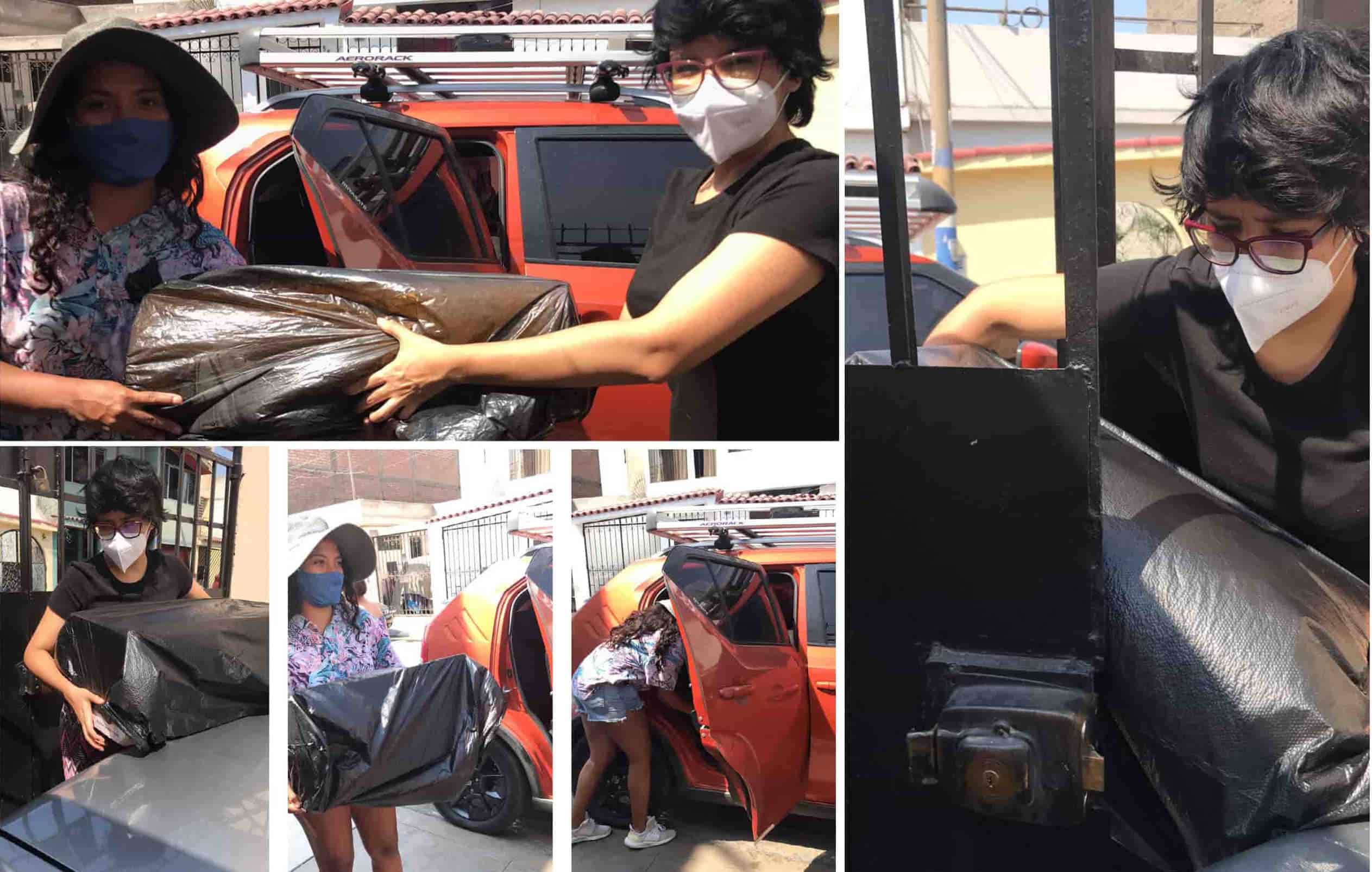
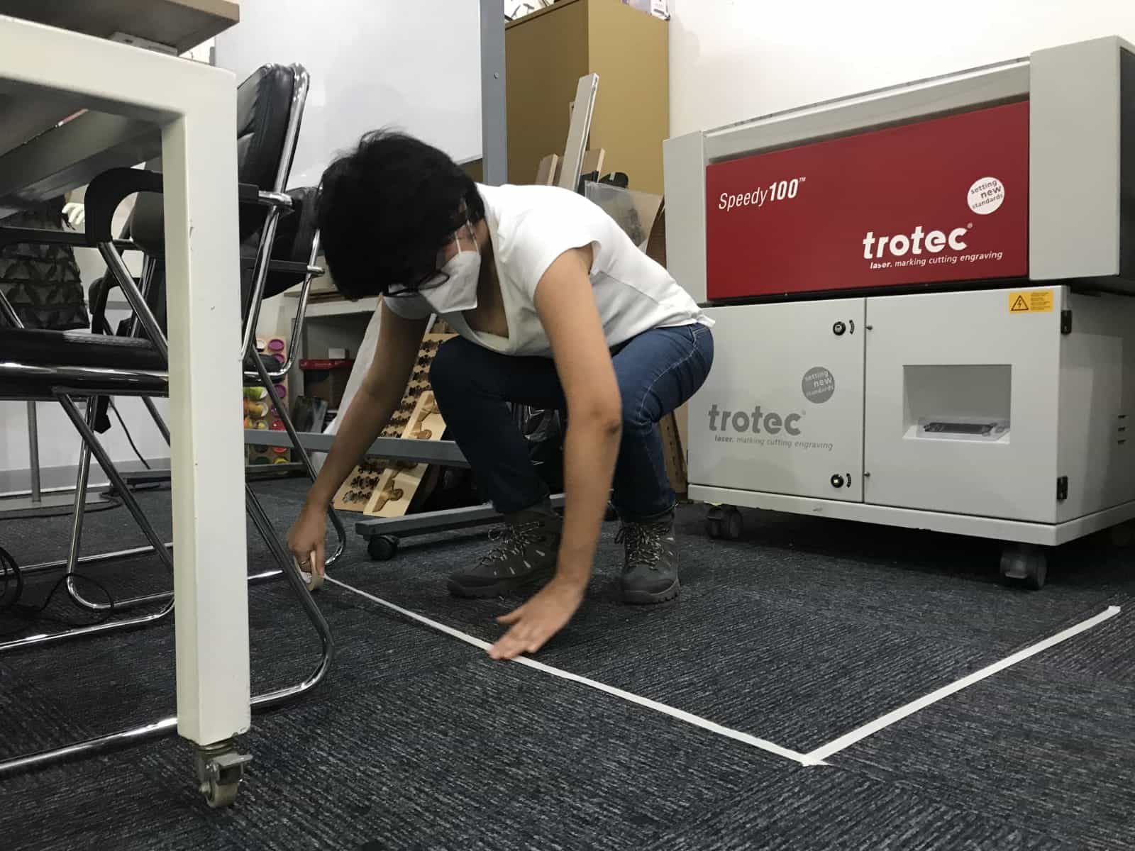
- The
first step is to have a safe working space, as the laboratory has not been used for a long time we first arranged things and freed the machine from contact with hazardous materials, it was also important to mark the floor because of the distance of use. 👍
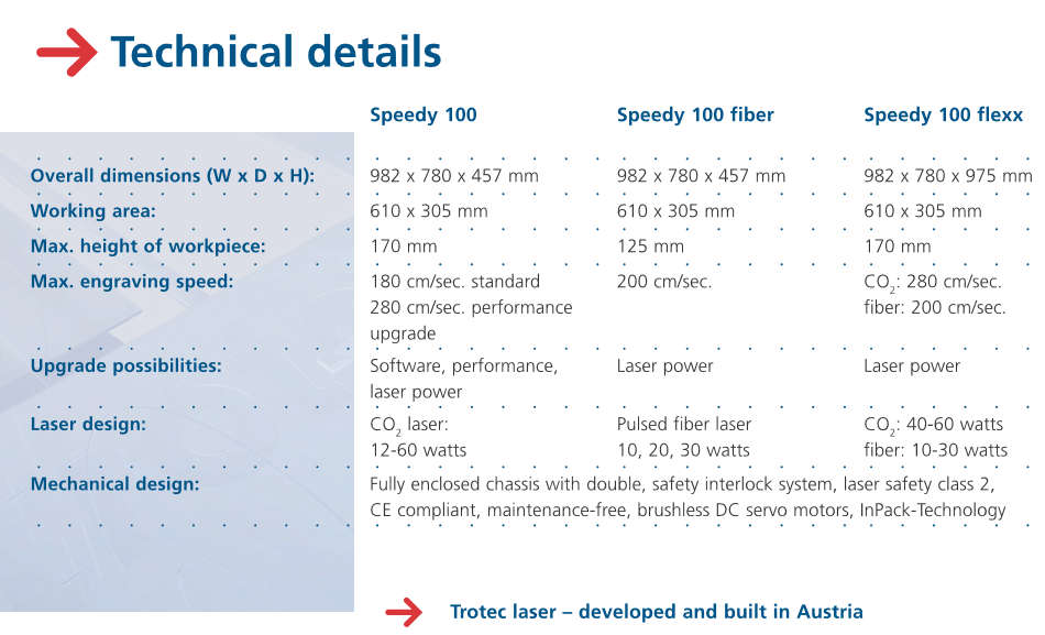
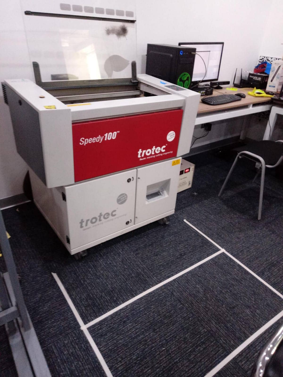
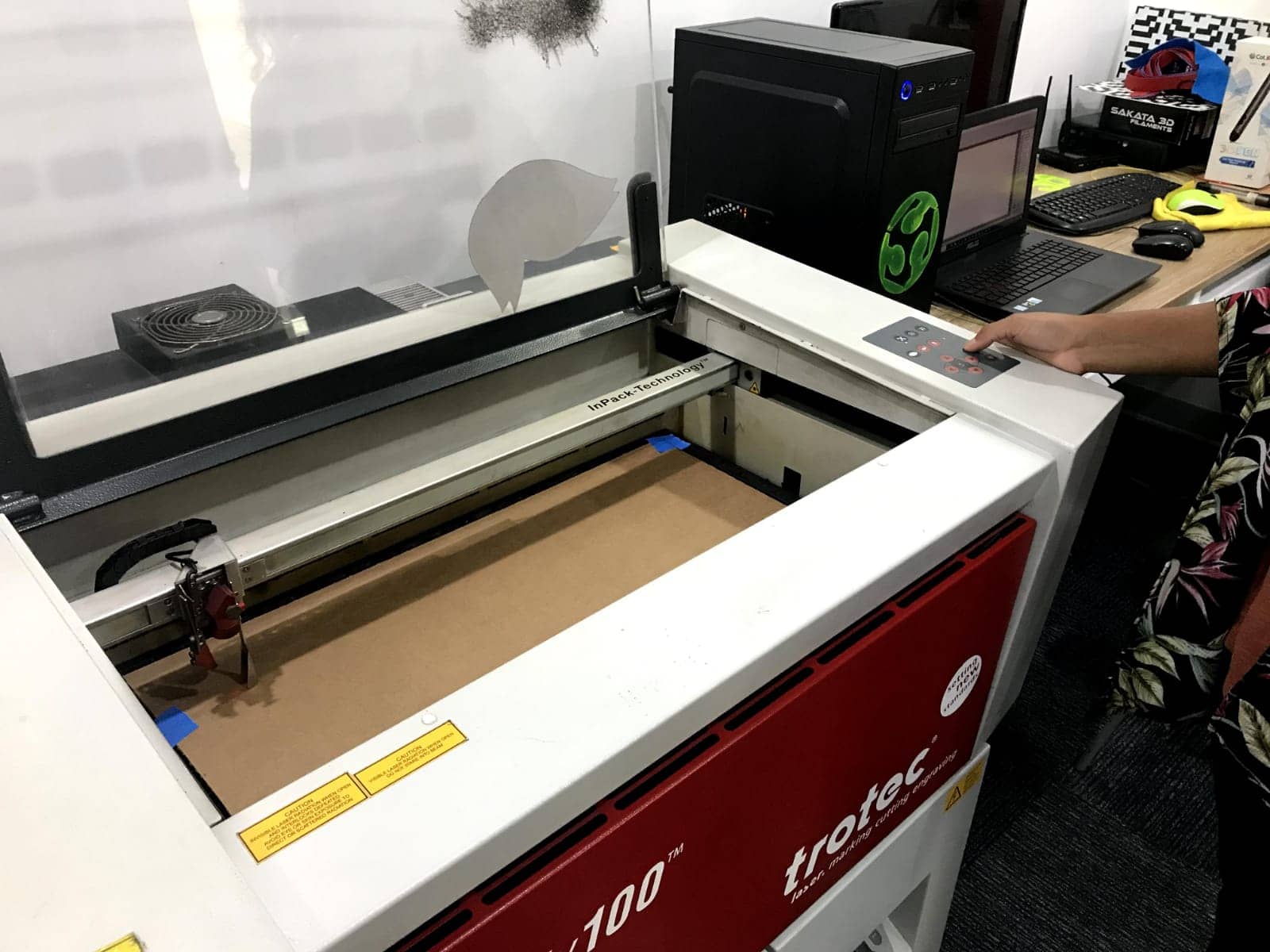
- Our machine is the
Speedy 100 Trotec Laser and has the following features:
MACHINE SIZE
974 mm width x 765 mm height x 457 mm depth
WORK SPACE
610 x 305 mm
LASER TUBE POWER
12 to 60 W
-
Font
- The
next step was to calibrate the machine and put our files into the computer. For this we had seen that there was a flaw in the lid, months ago a fire occurred due to a bad maneuver or lack of supervision of the cutting in development, fortunately it is only a superficial damage. 😫
- As a
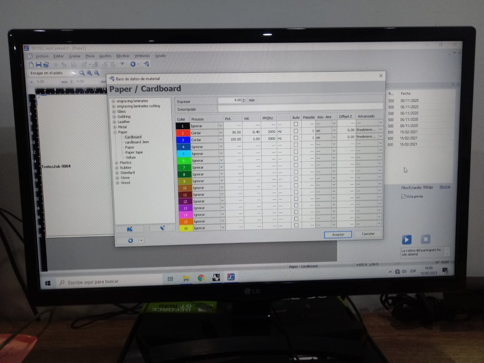
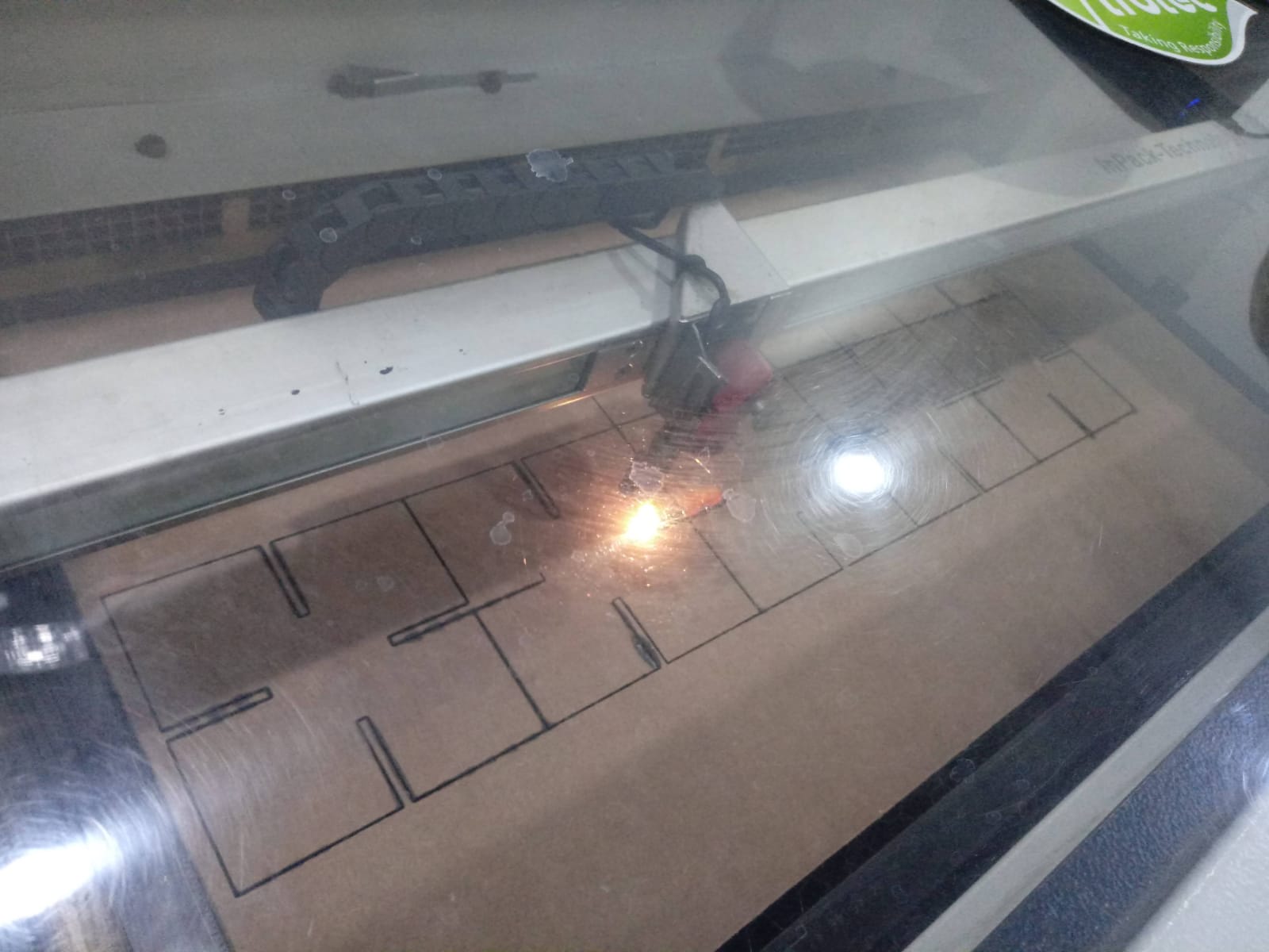
next step we did a test on 4mm cardboard because happily we got an open store that only had that material.
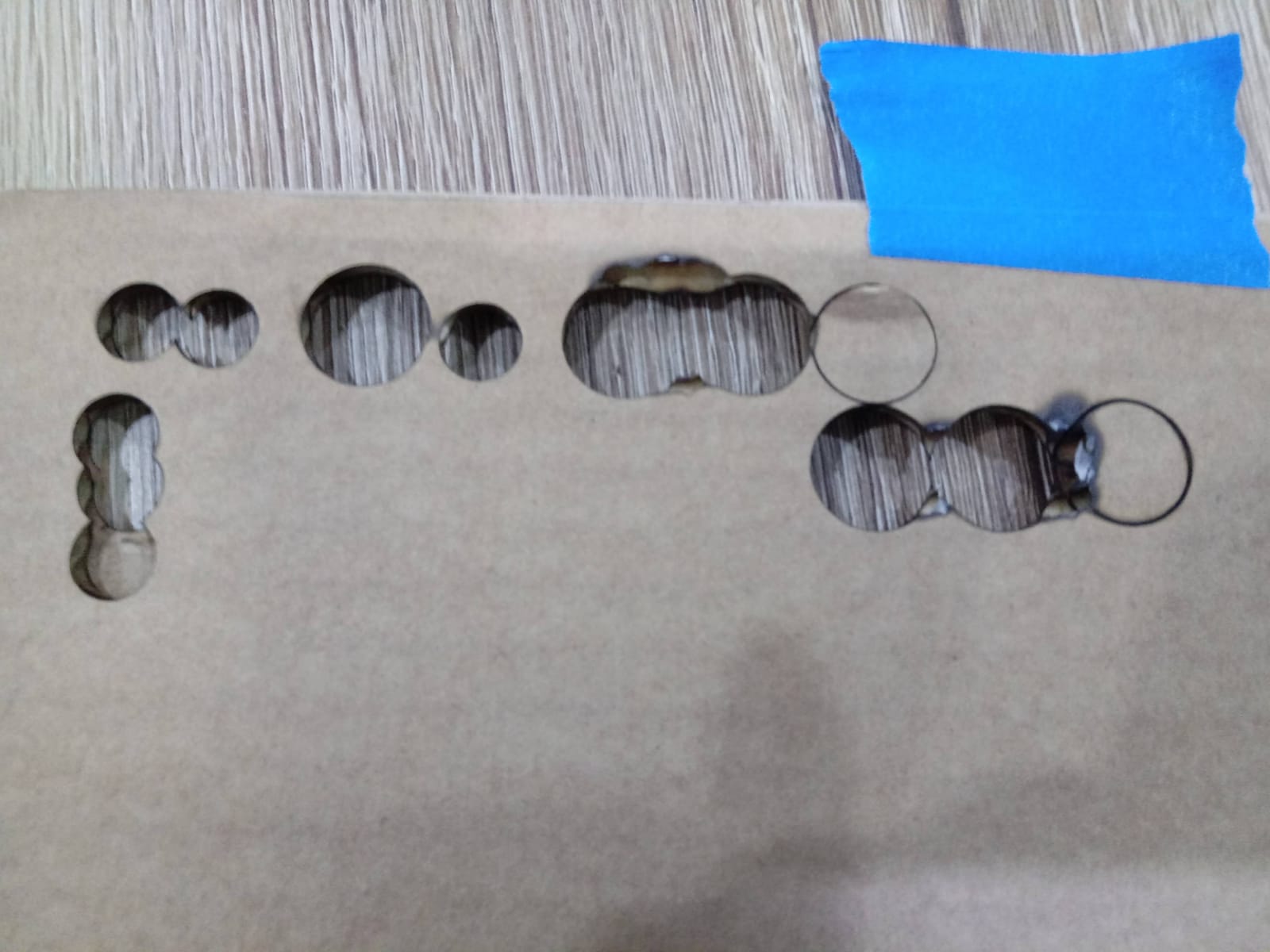
- Everything seemed to be
fine, however the parameters did not work when we had the larger pieces cut. 😩
The cardboard began to catch fire
- At first we thought that the reason why it was not working was because we got a message about the
filter, I remember that the laboratory team told us that it had to be changed some time ago. In the following picture I show the lower part of the machine with the message
"change filter". However, we talked to the
LEFO specialist and he told us that it could be two things, either the focus is bad or the lens is super dirty and needs cleaning, so far we have concluded that it is the lens, we have done many tests and we have not achieved a good calibration.

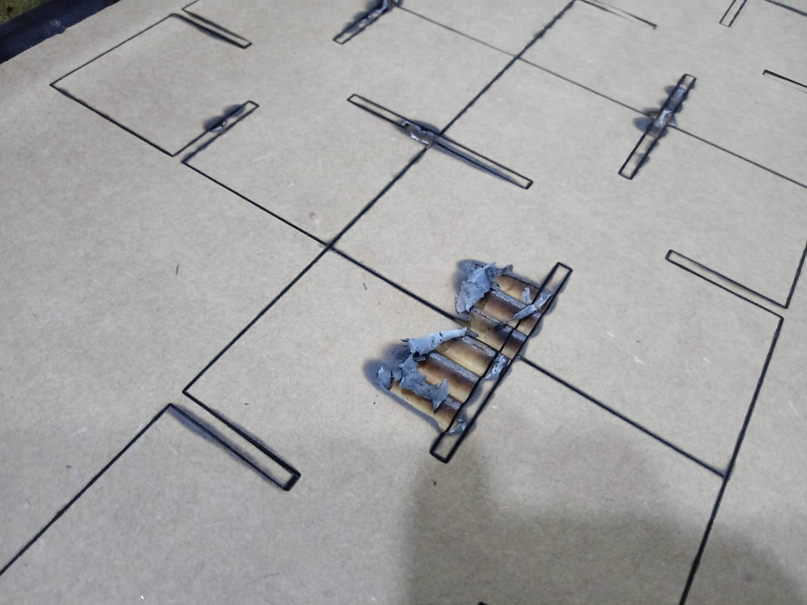
- As can be seen in the following
photograph, the tests did not change, when we increased the power a little and lowered the speed, fire came out and when we inverted the values, it did not cut very deep.
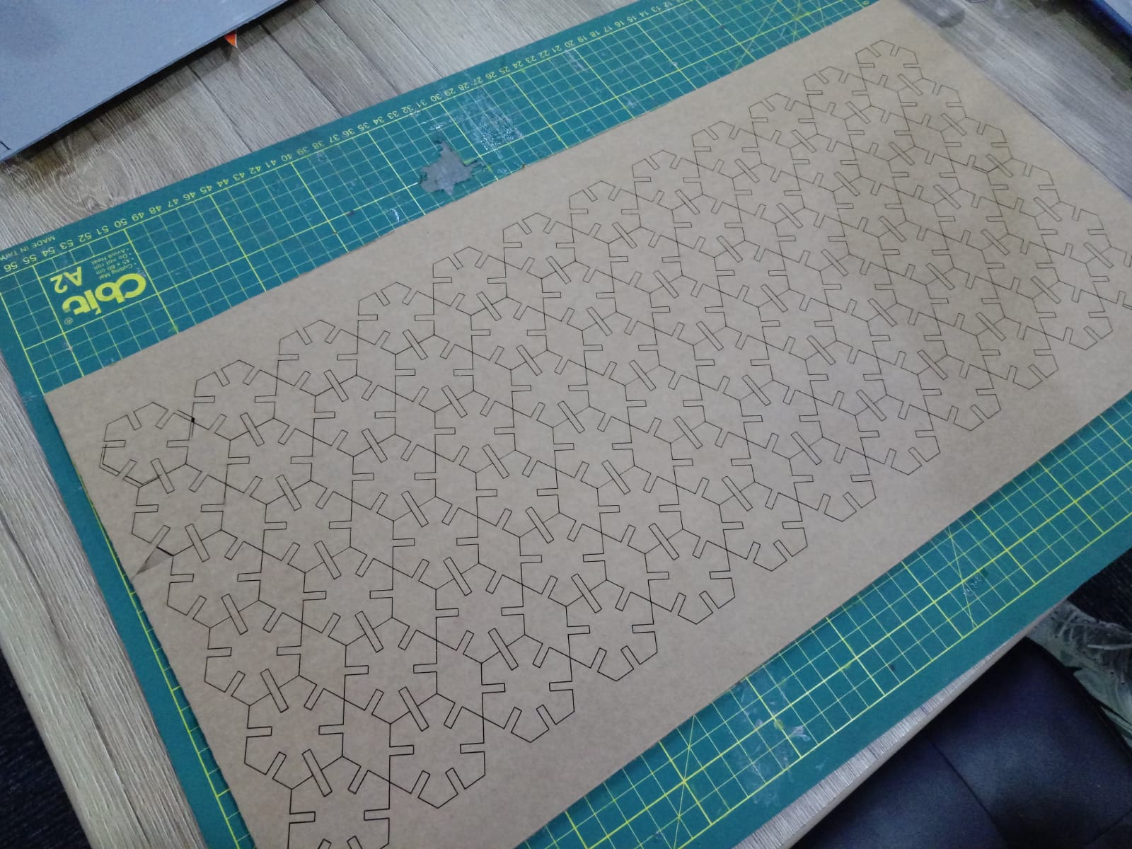
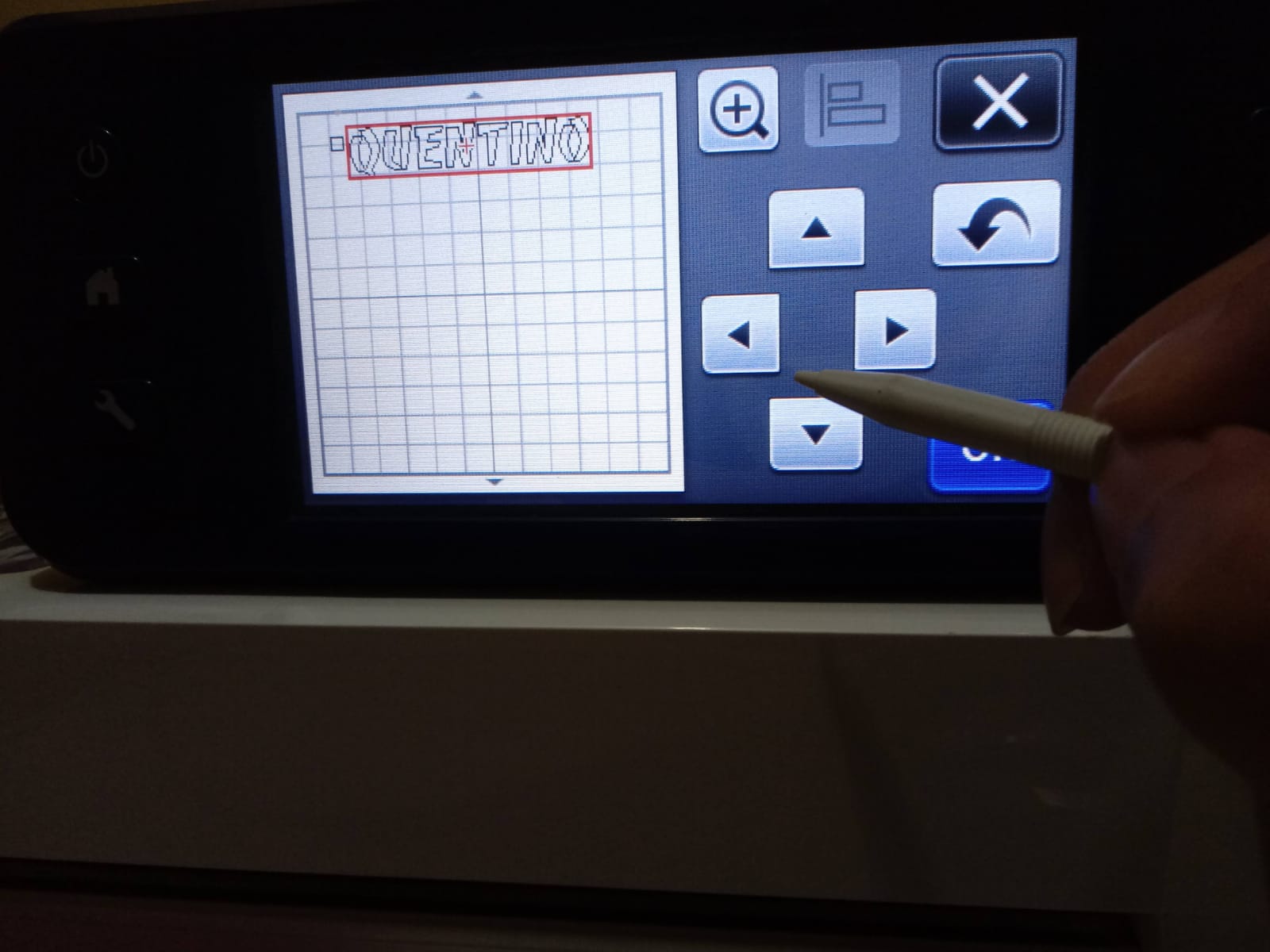
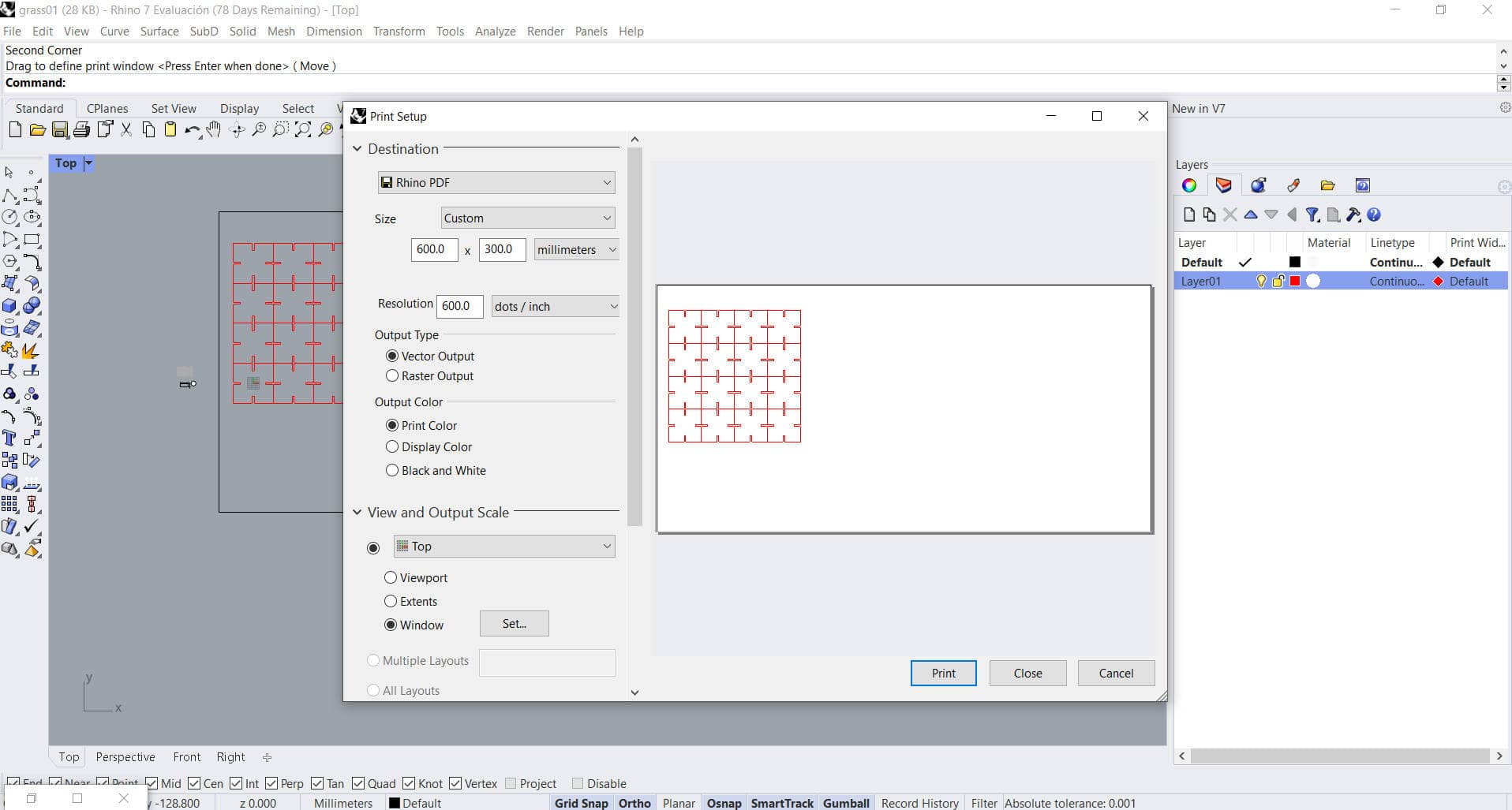
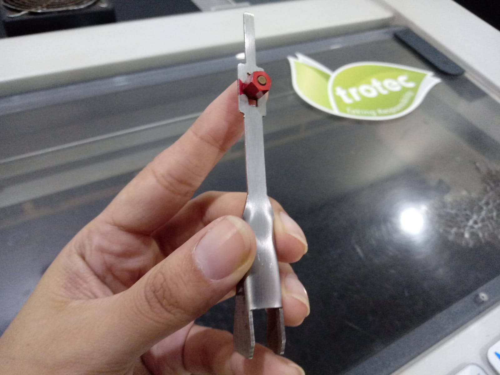
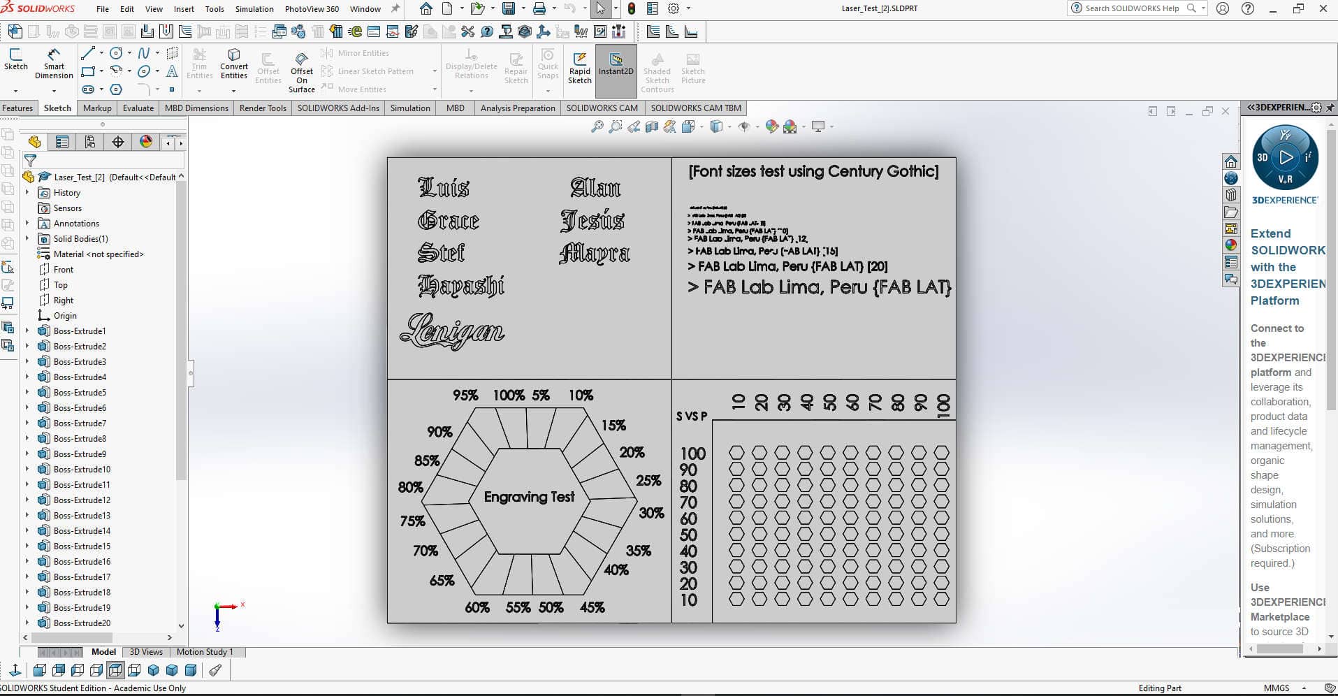
- Due to the inoperative machine and the short time available in the lab, we were not able to cut on the
Trotec Speedy 100 yet, but we had the file of our designs ready as you can see below.
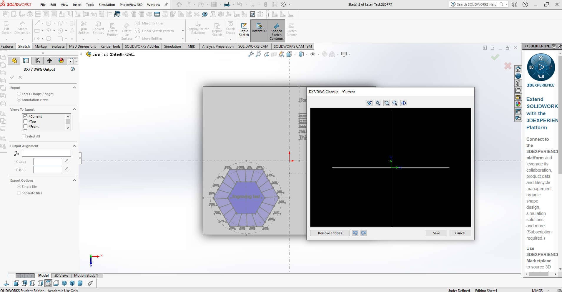
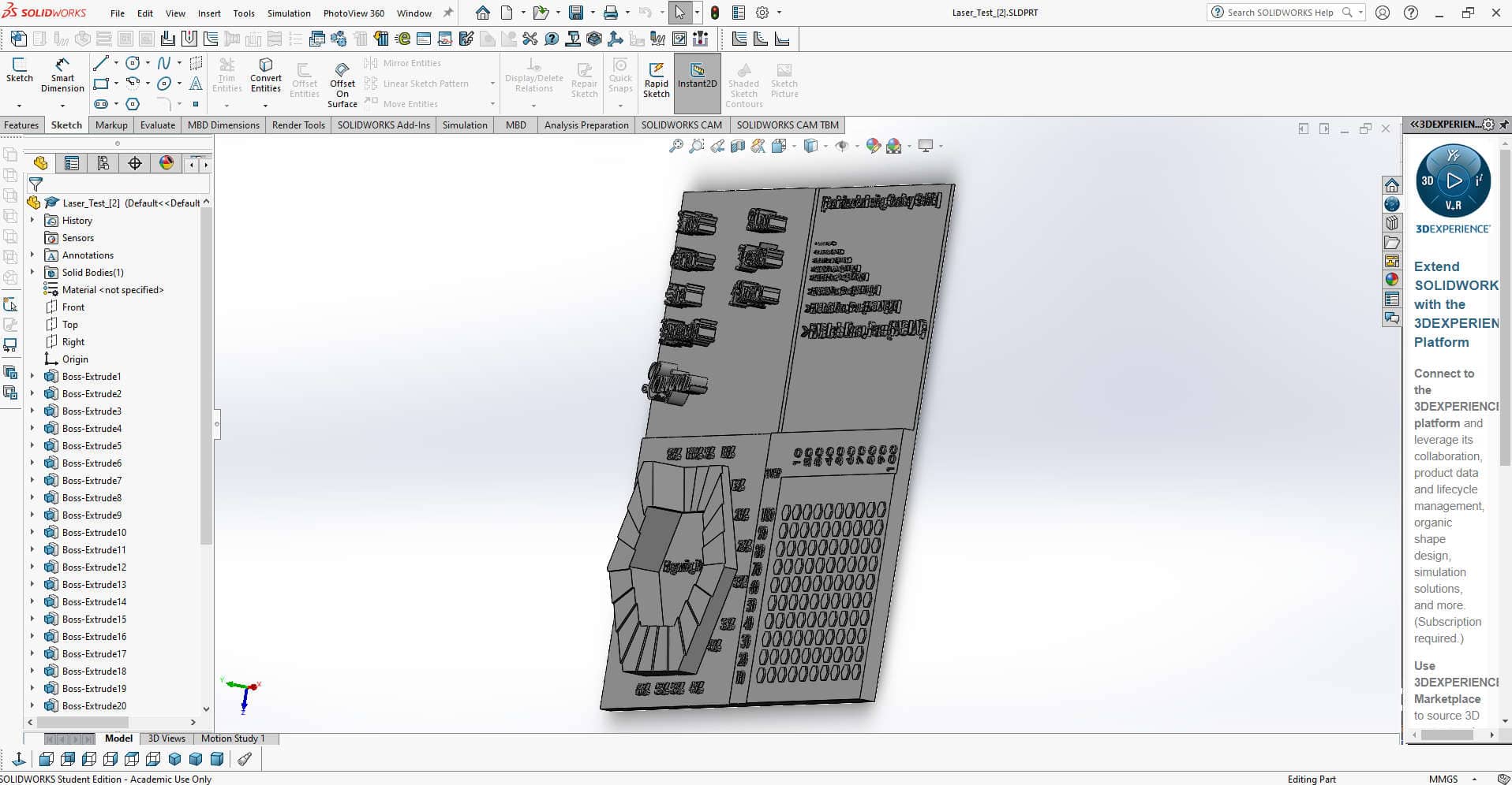
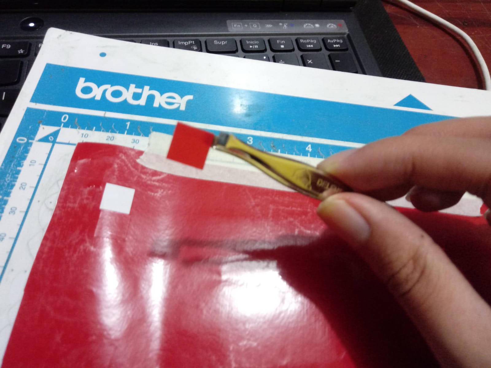
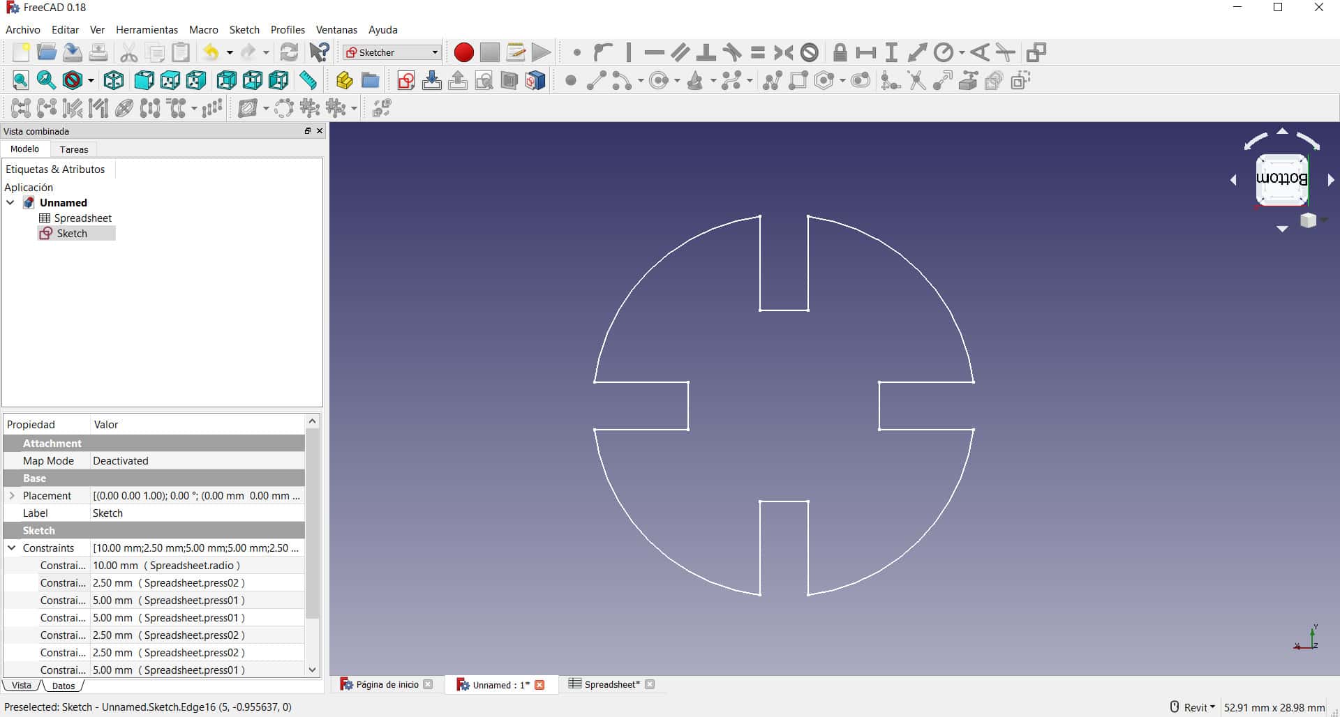
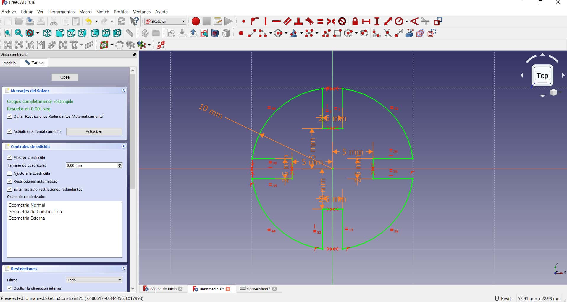
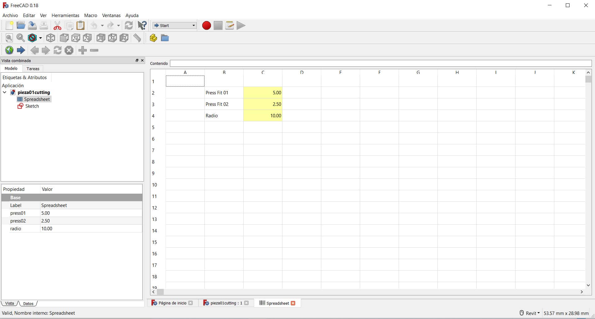
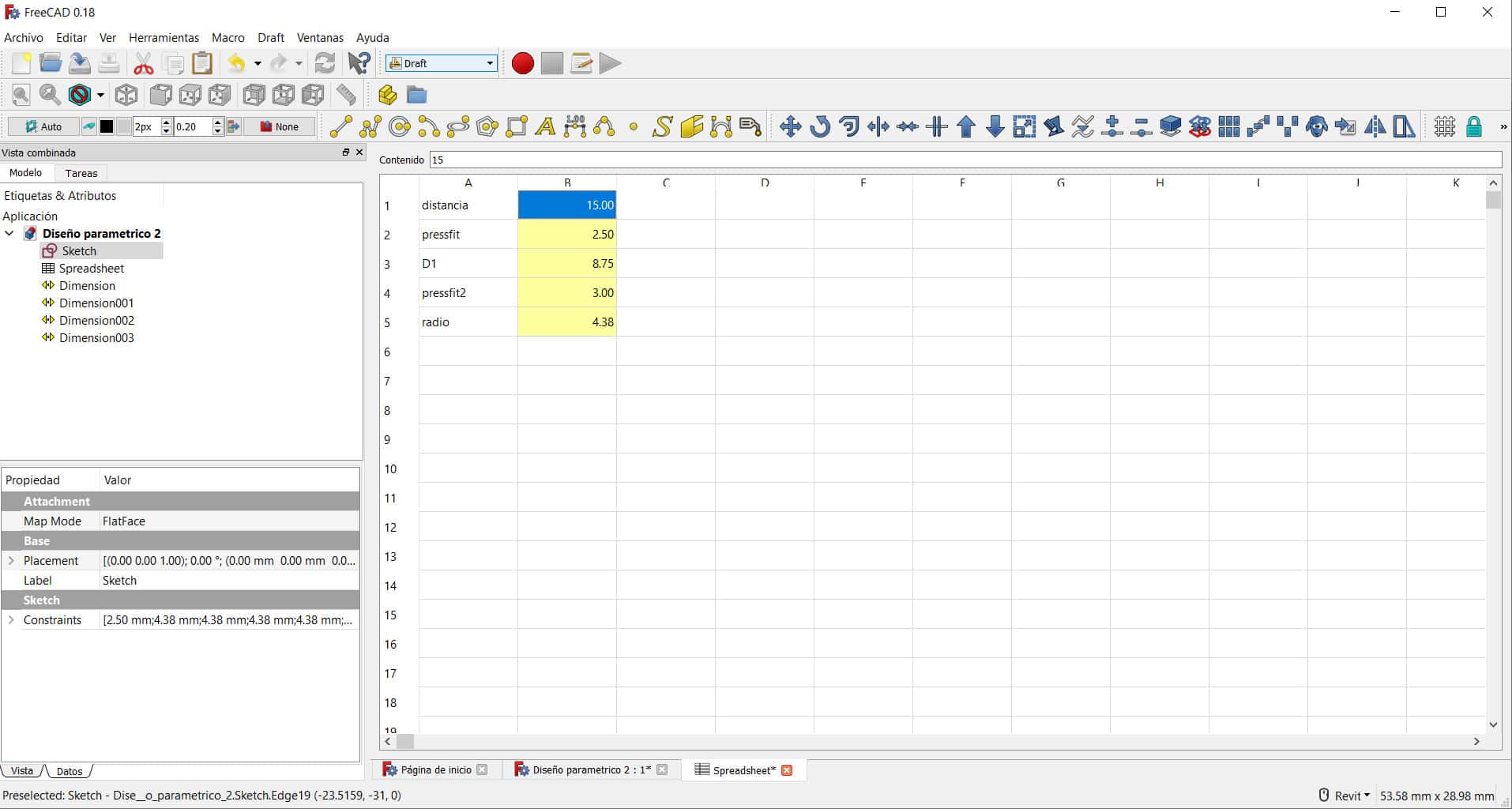
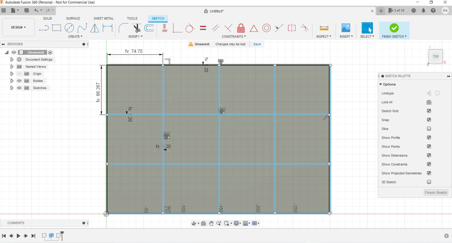
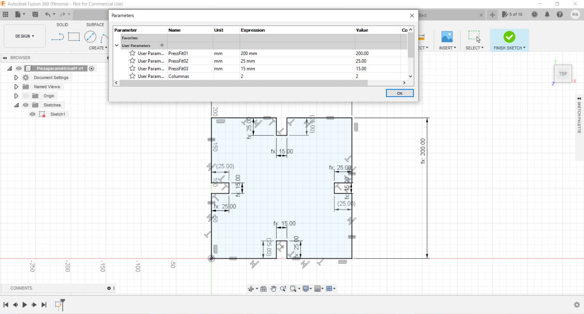
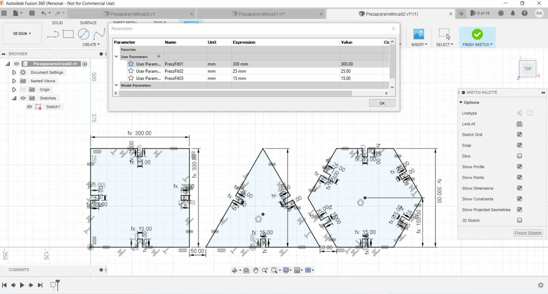
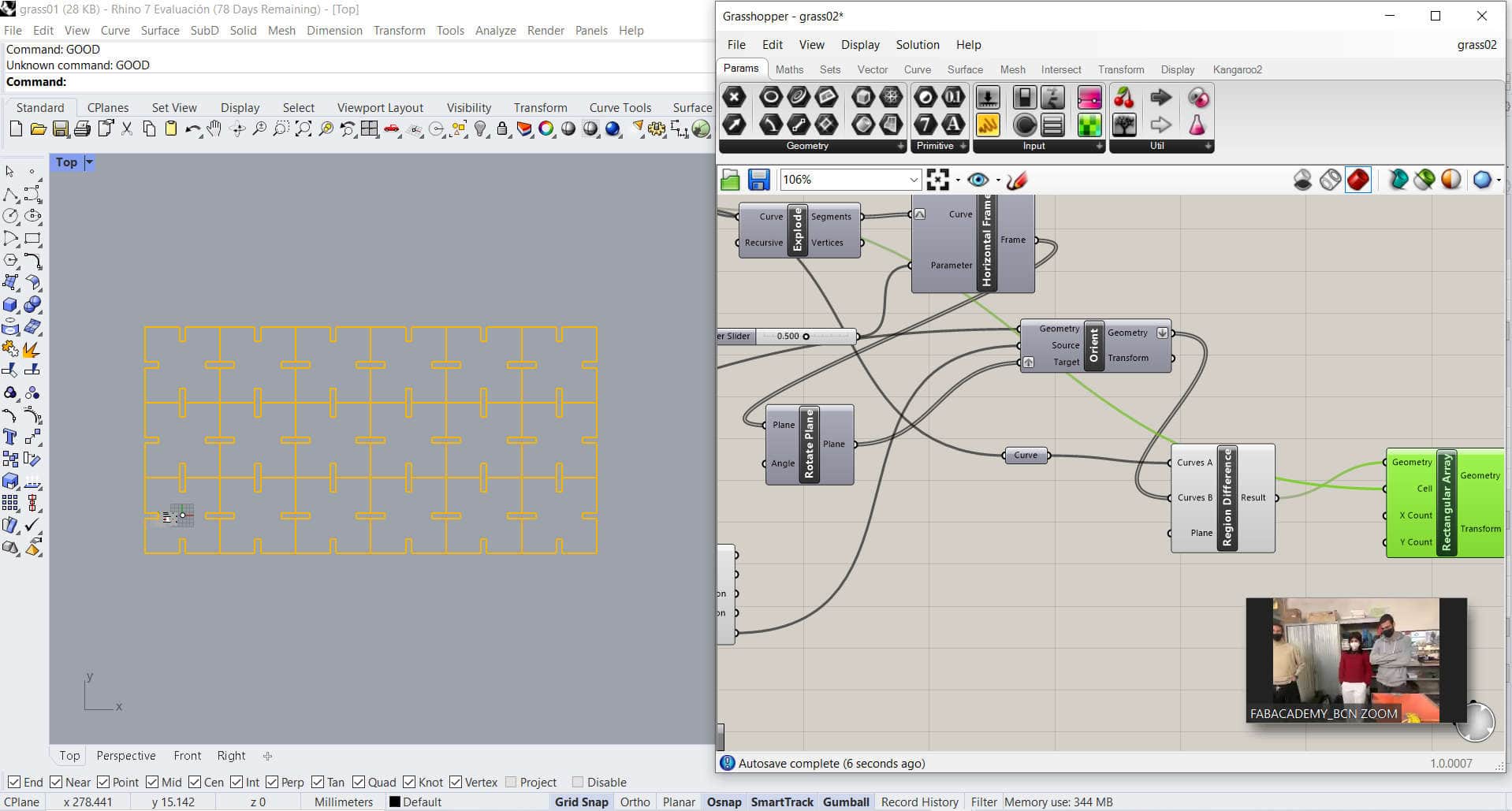
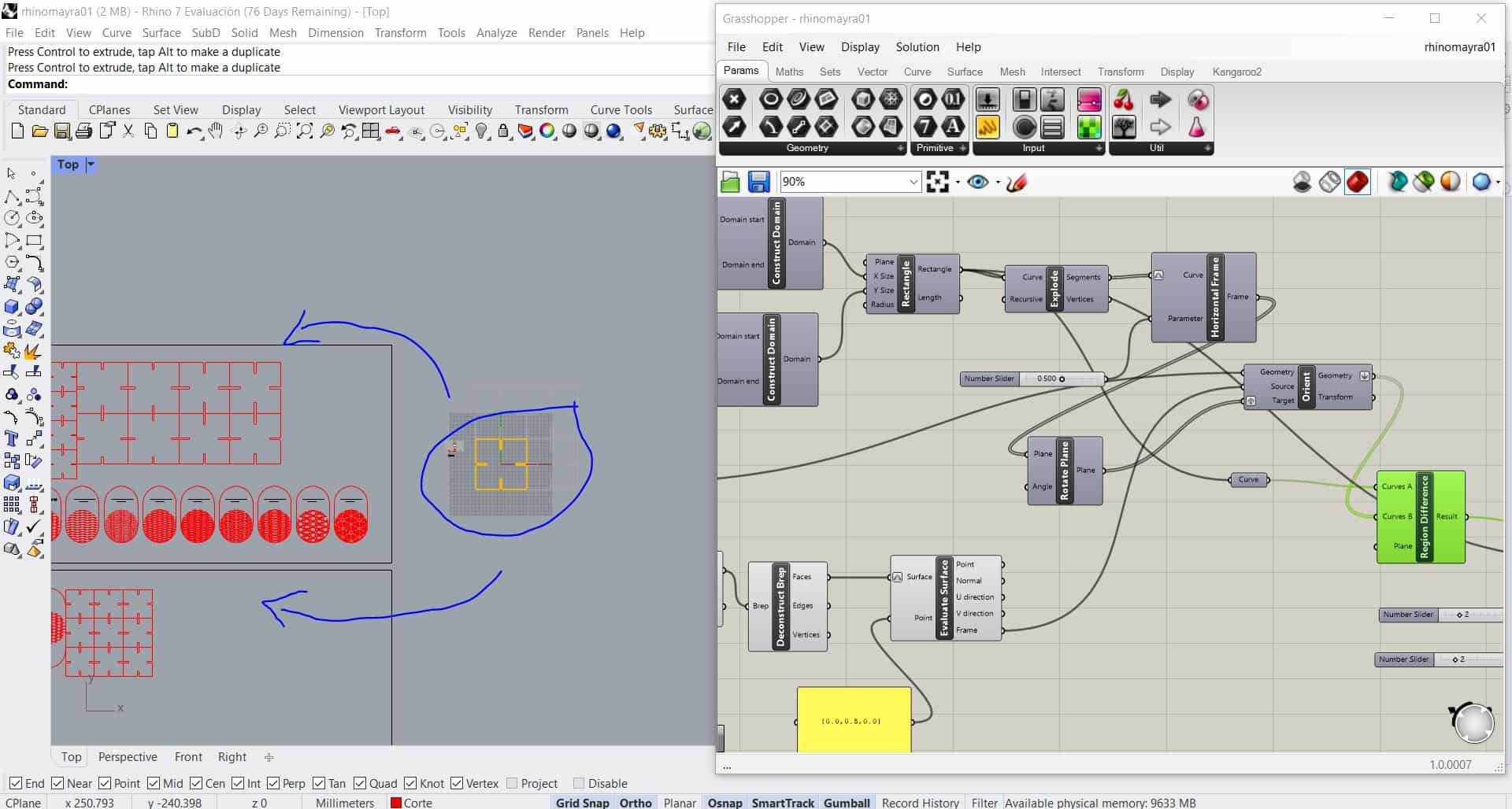
- The part can be designed in any program that has
2D/3D capabilities and that exports files in DXF (Drawing Interchange Format) format. We decided to create the laser tester in
SolidWorks. While we were working on the design, we notice a problem… For some reason we notice that SolidWorks wasn’t creating the DXF file correctly. We saw a preview of the DXF file that SolidWorks was creating and some vectors were missing. This anomaly didn’t happen with older version of SolidWorks so we assumed it could be a bug exclusive to the
2020 version. The best way to solve this problem was to create a 3D representation so that SolidWorks could have a better idea of what we wanted. After doing this SolidWorks was able to create the DXF file perfectly.
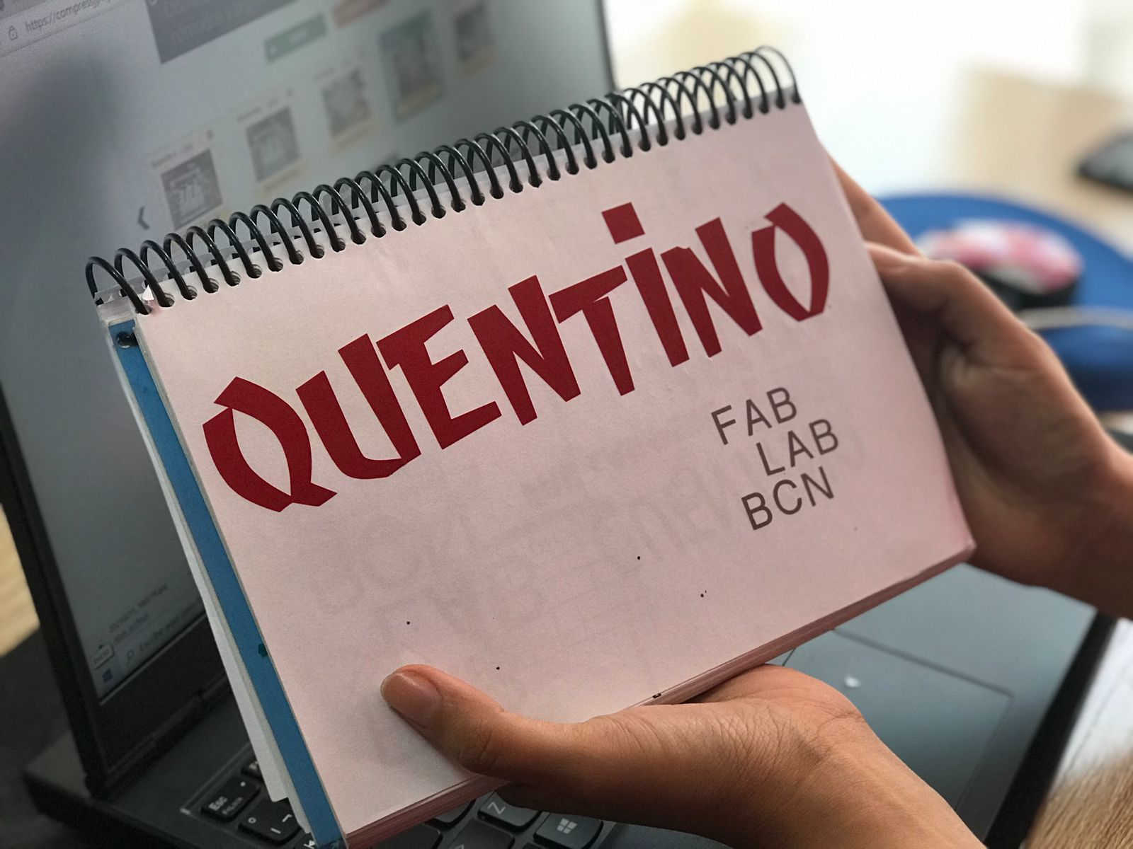
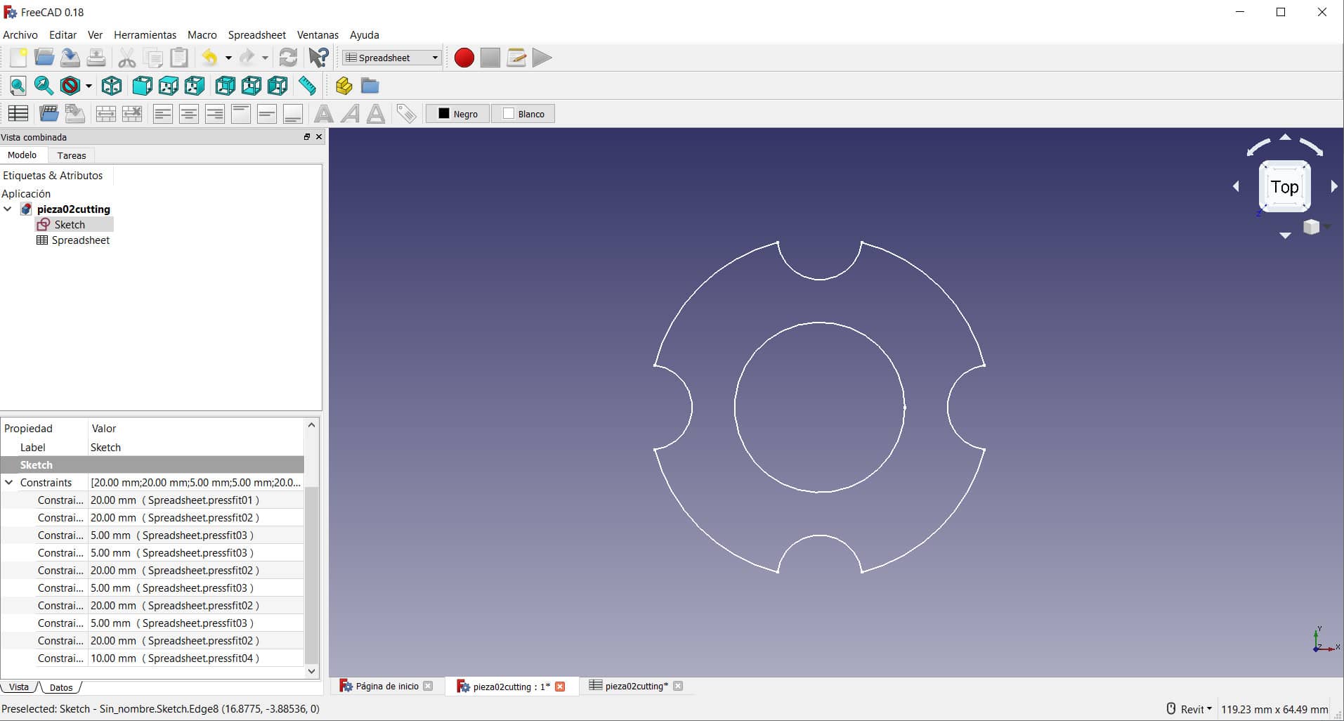
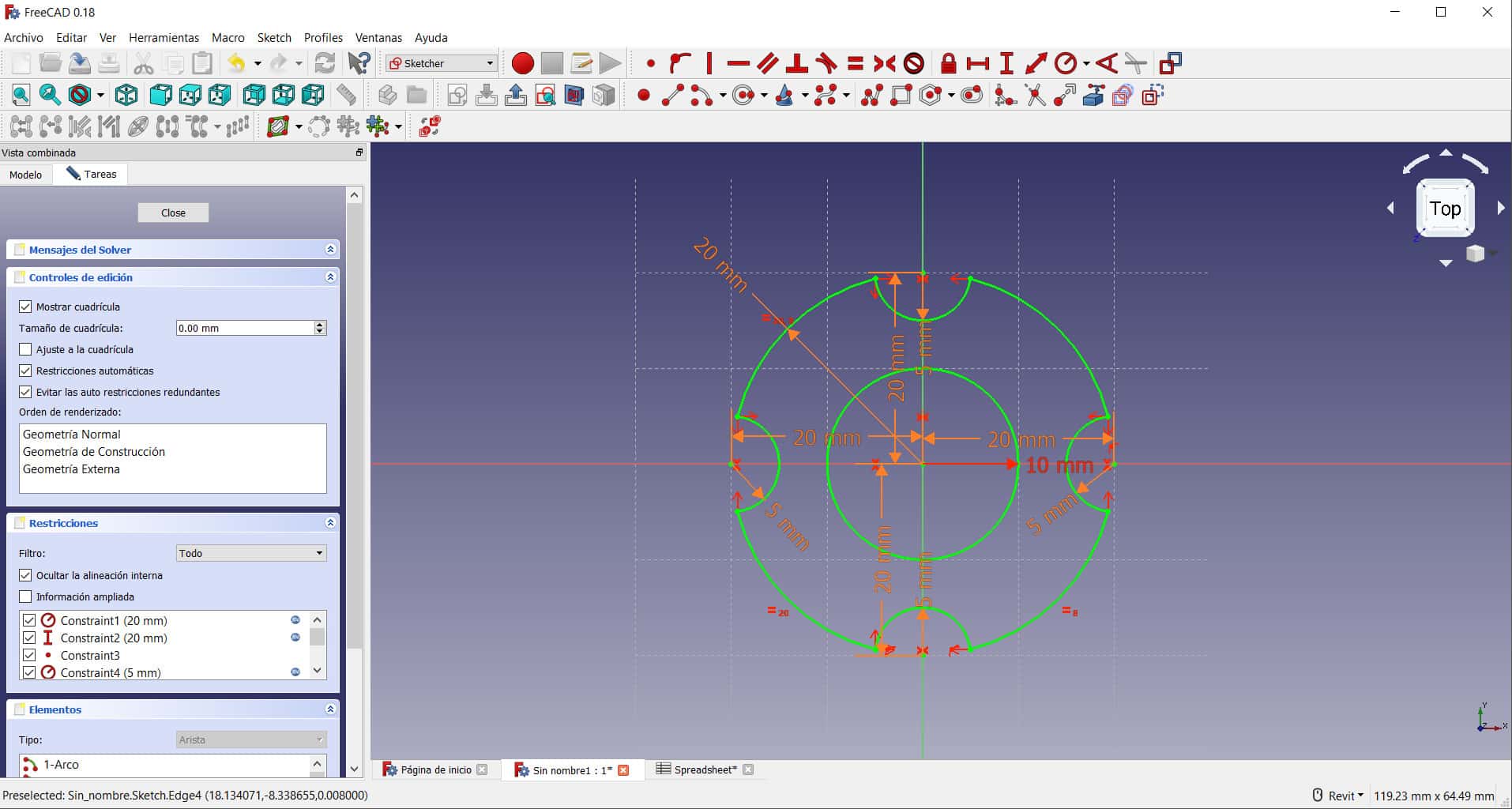
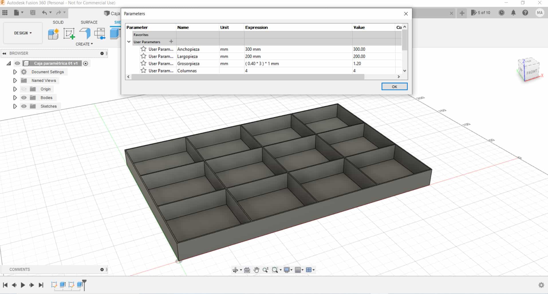
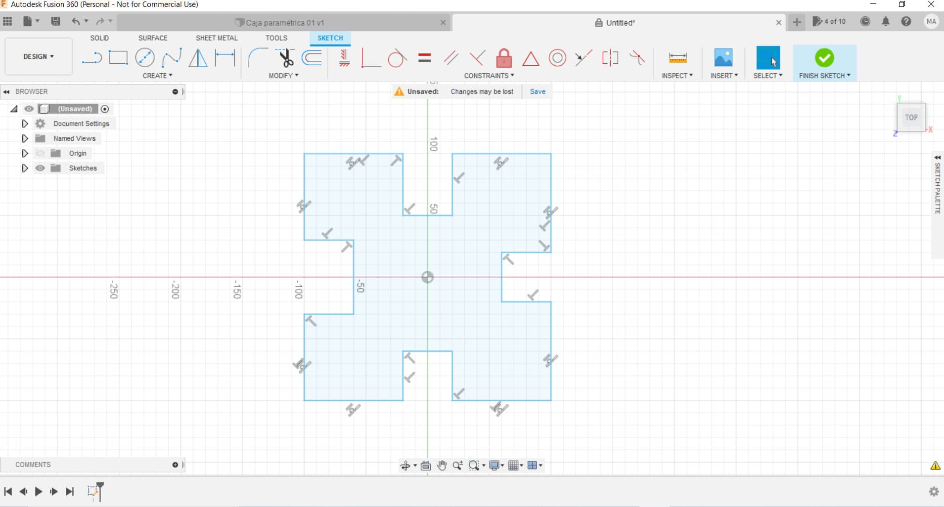
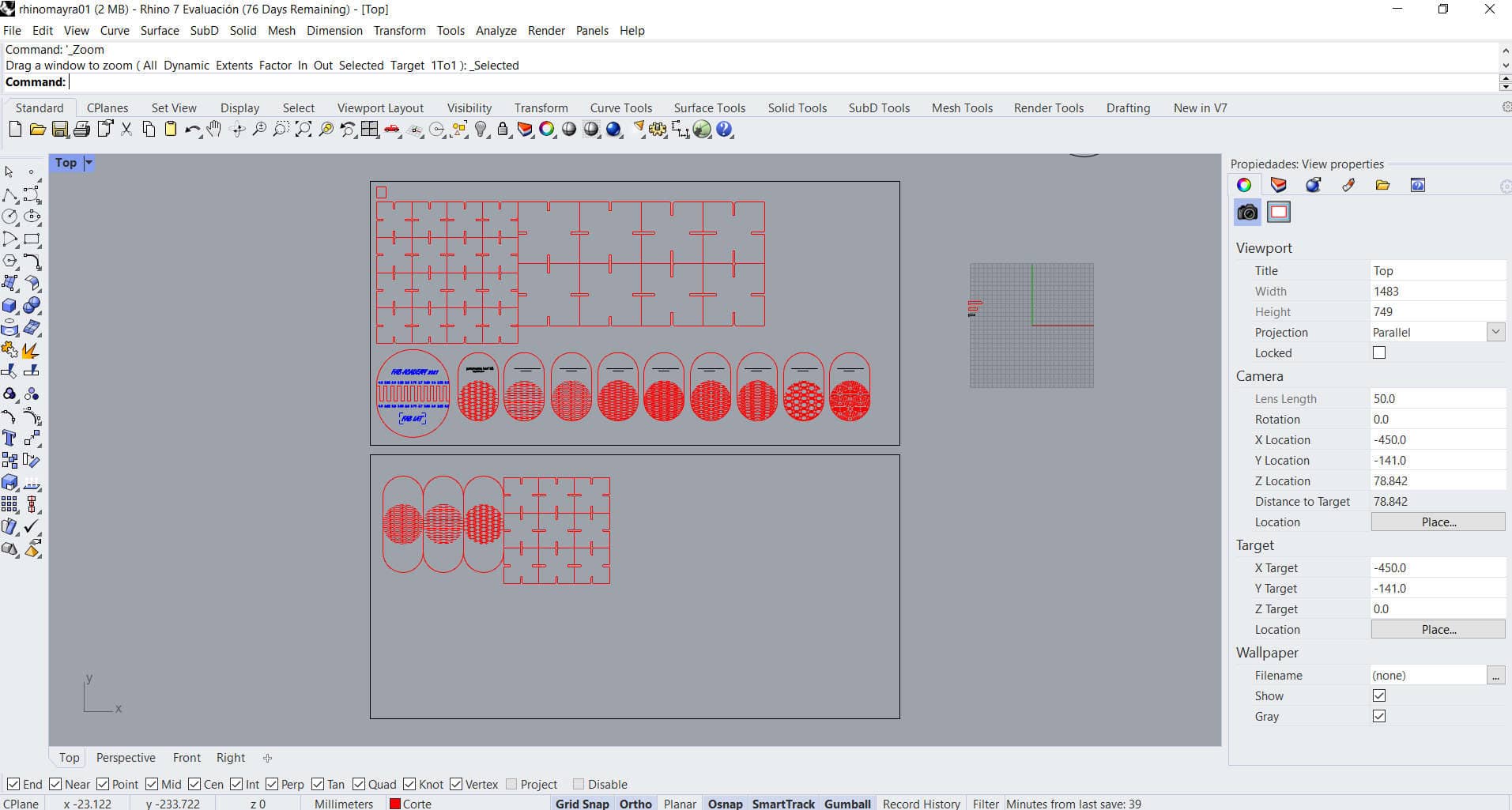
Final design
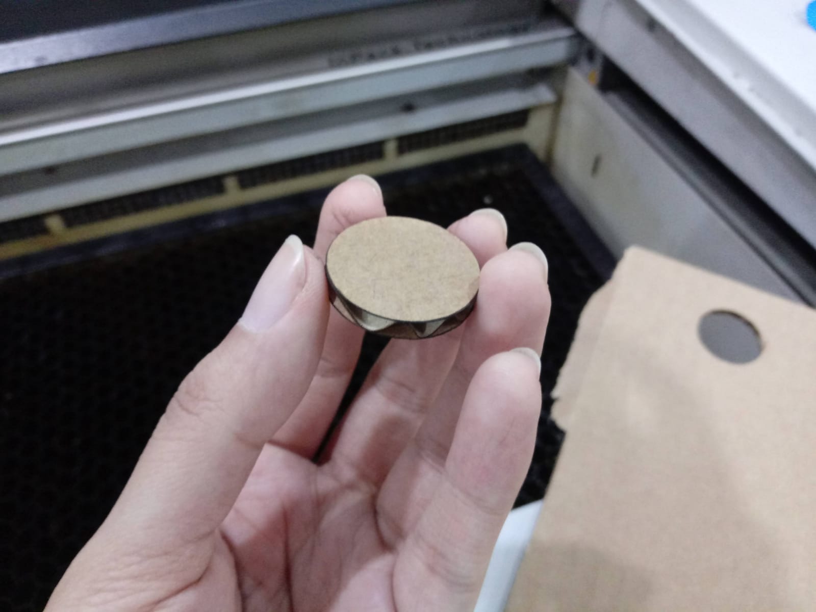
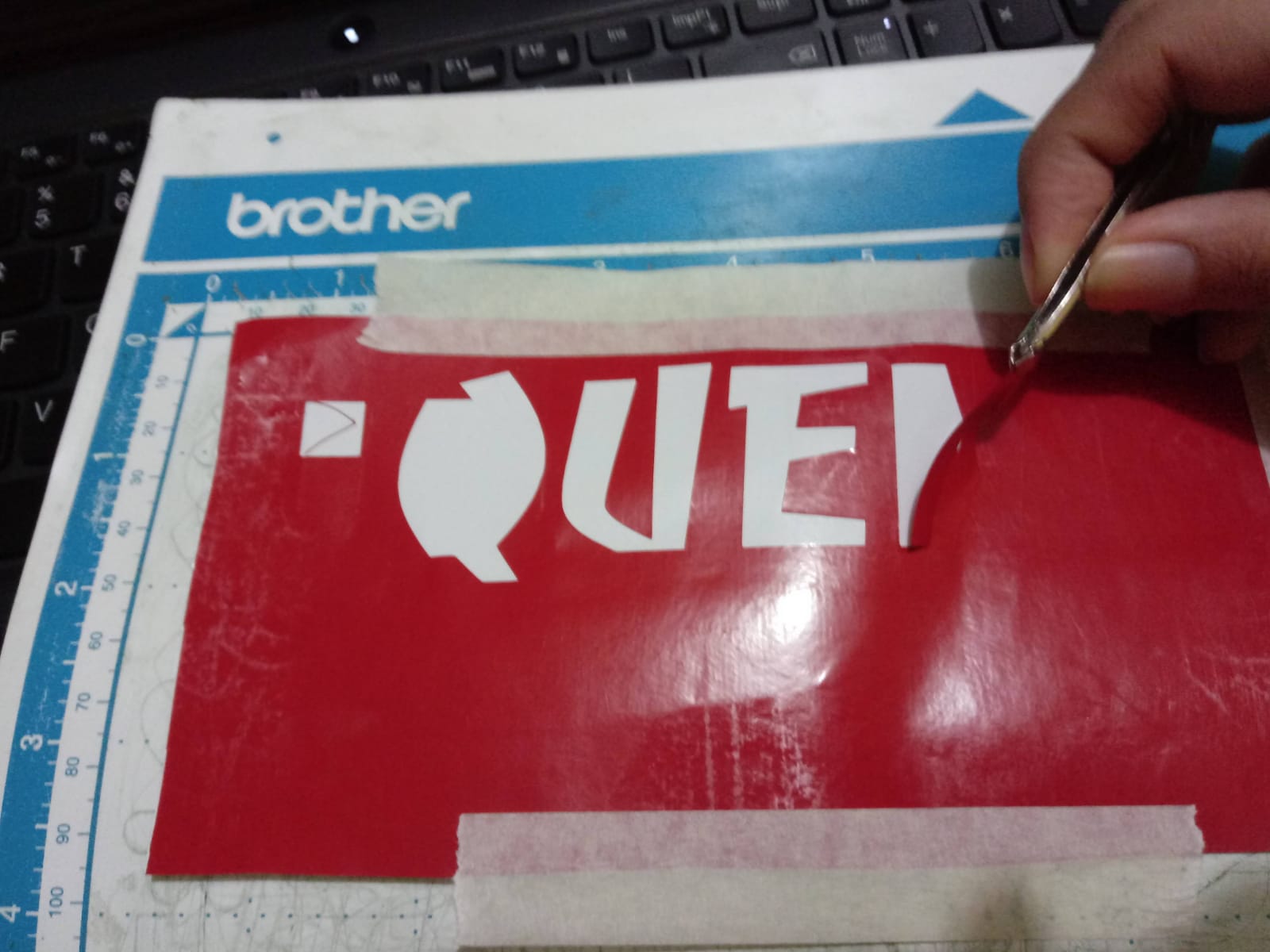
- Well,
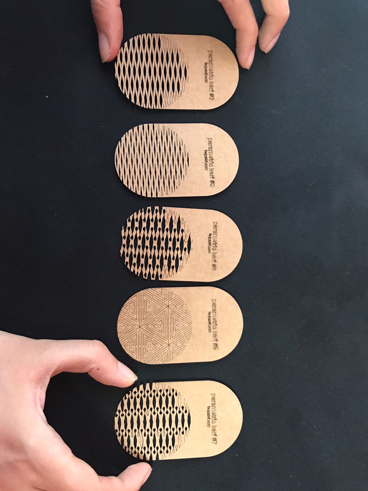
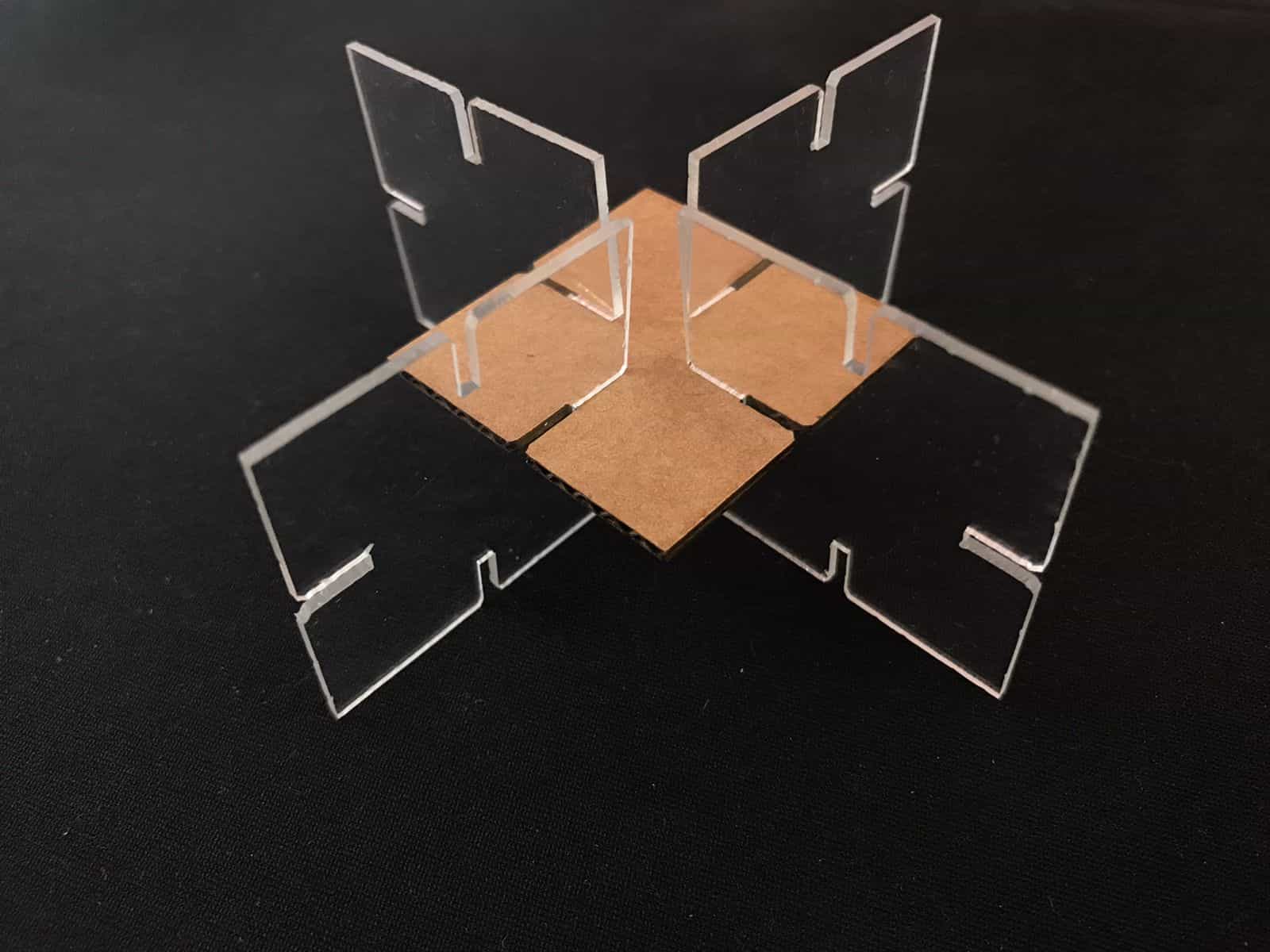
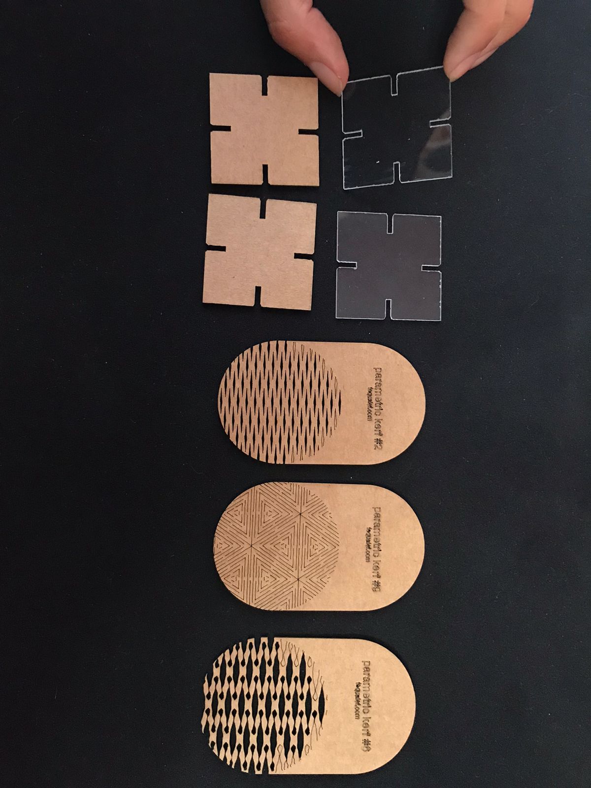
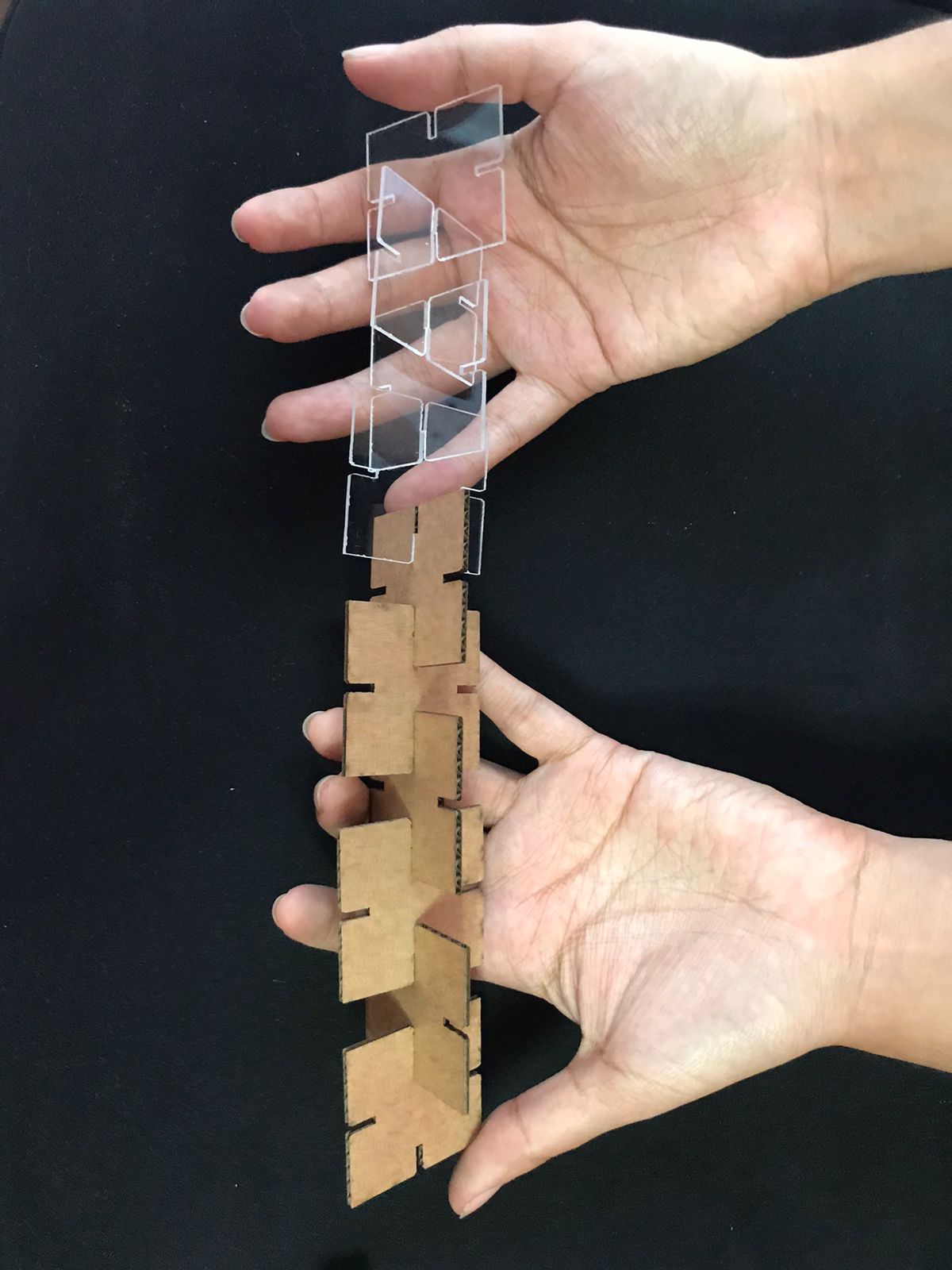
it wasn't all bad, we got a laser cutter outside the Fab Lab and were able to test some of our files. It was important to see the difference in behavior of at least
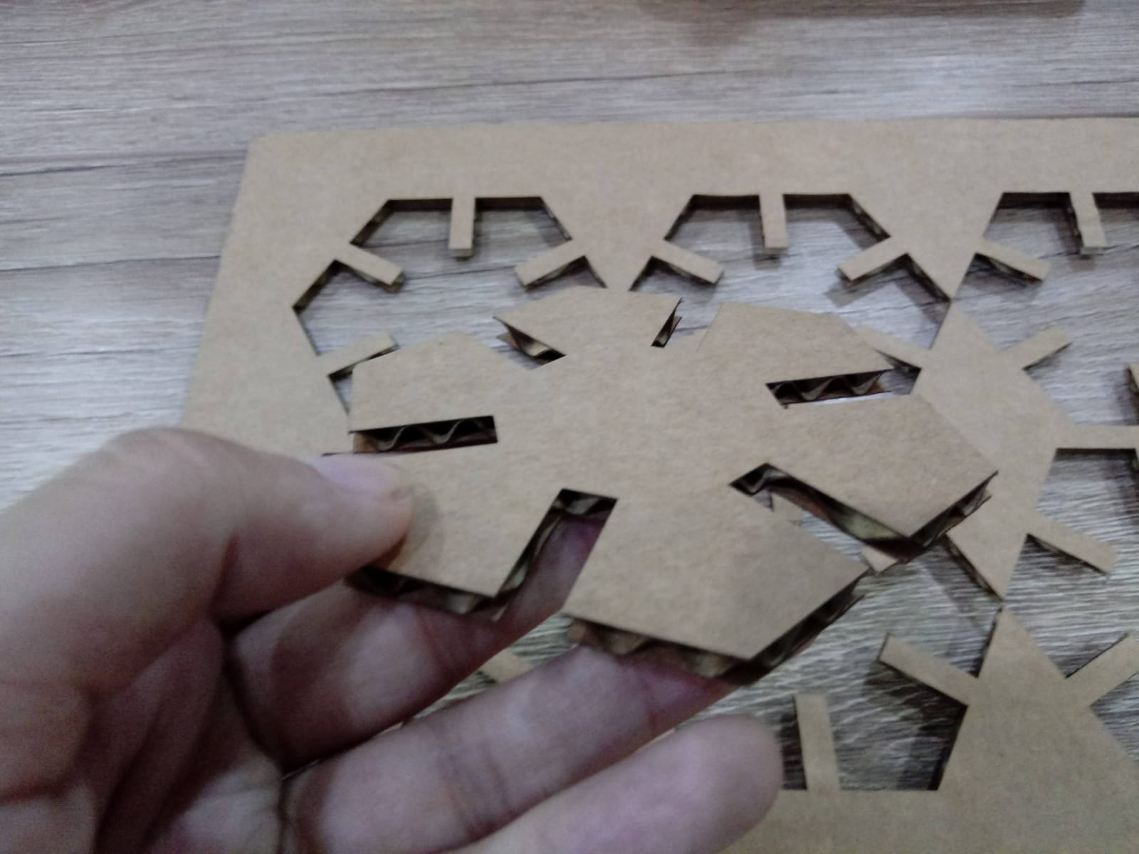
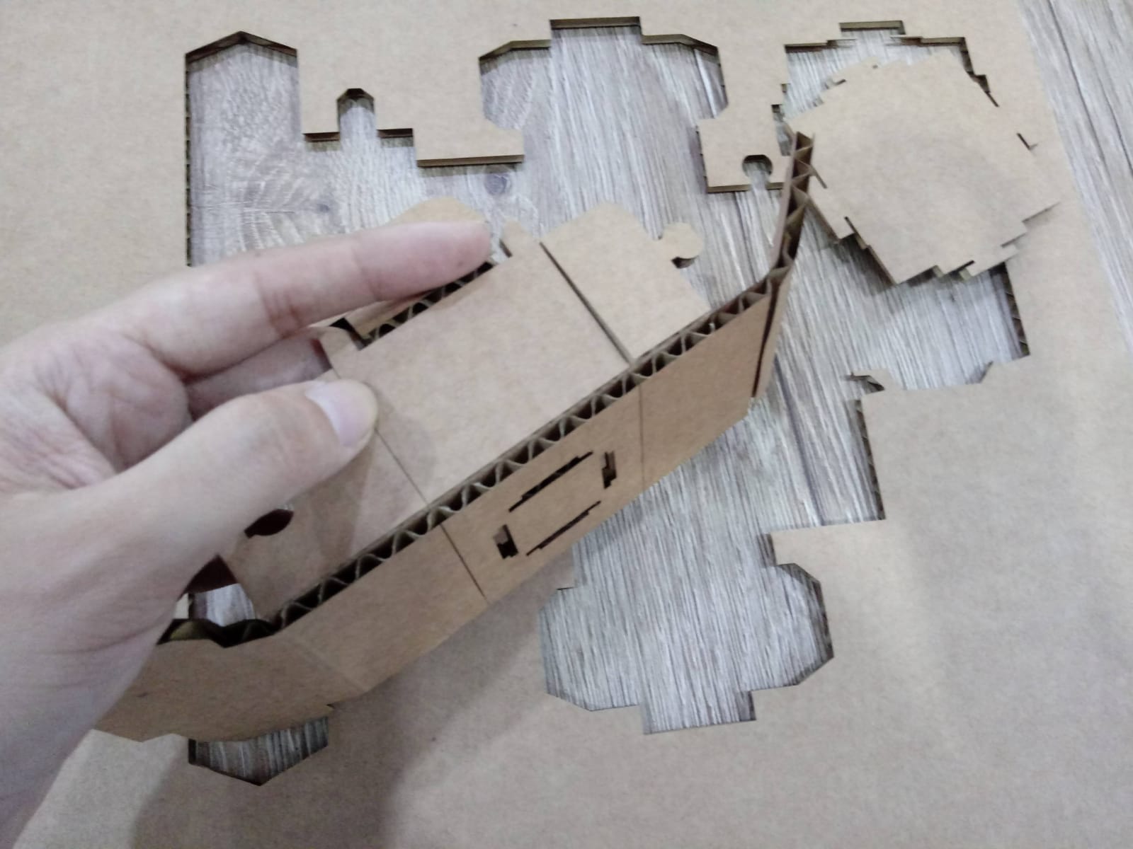
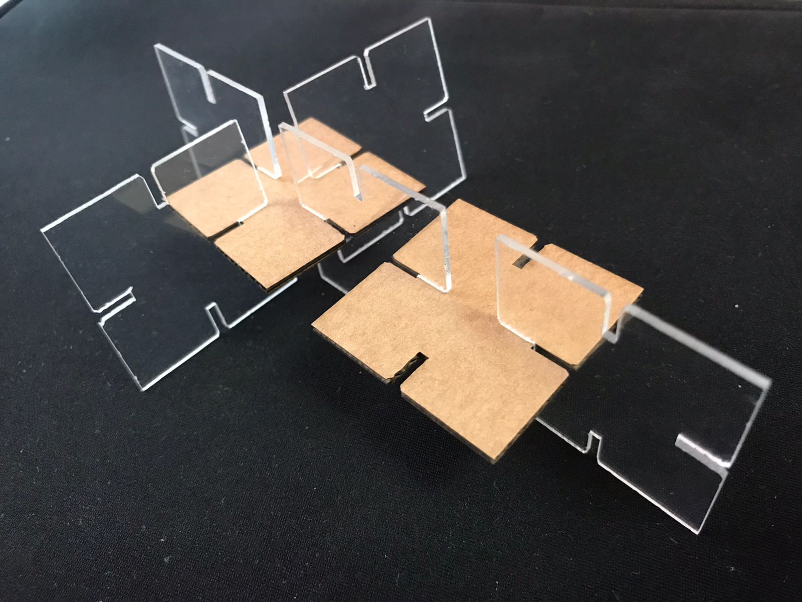
two different materials so we chose cardboard and clear acrylic. In order to be able to not only think in flat pieces we were also inspired by the
Instructables pieces and generated some variants to test our cuts.
Curved Laser Bent Cardboard - Acrilic
Curved Laser Bent Cardboard
- The parameters we used were:
Cut:
4mm Cardboard: 60 Power, 1 Speed, 1000 PPI
4mm Acrilic: 30 Power, 0,3 Speed, 5000 PPI
Engrave:
4mm Cardboard: 30 Power, 100 Speed, 1000 PPI
This is the
first experience we had as a team and we will come back to solve the Fab cutter system and also learn about the maintenance and cleaning of a laser cutter.💪
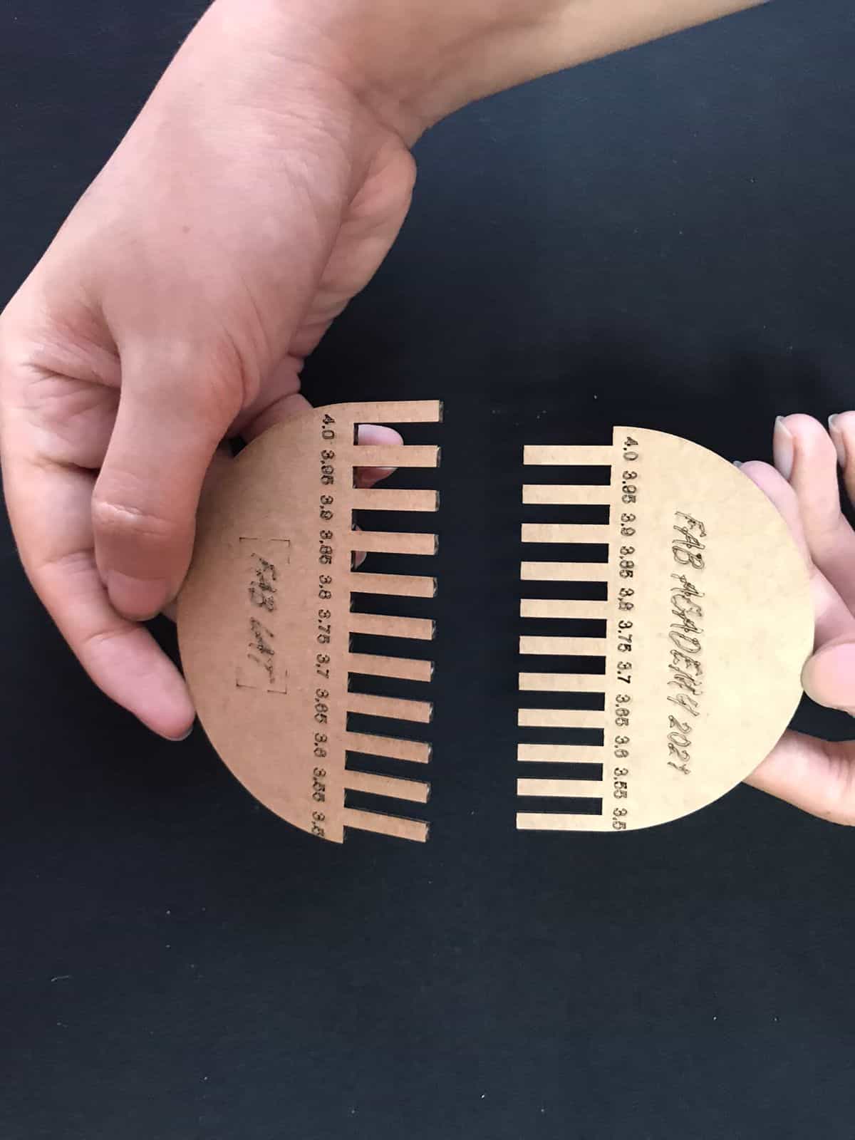
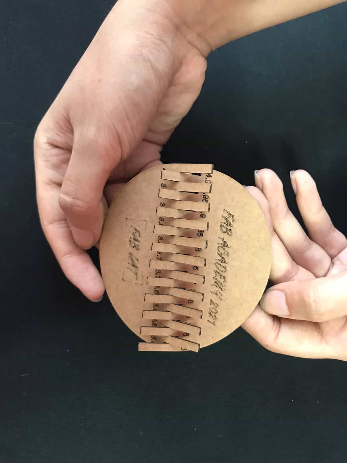
As additional information, after making the cuts we realized that the
tolerance had a measurement of
0.15 mm, that is to say that if the original dimension of our drawing is
10 cm, when we cut it we obtain
9.85 cm, this is an important point to consider before making a very precise work. ✋
Special moment
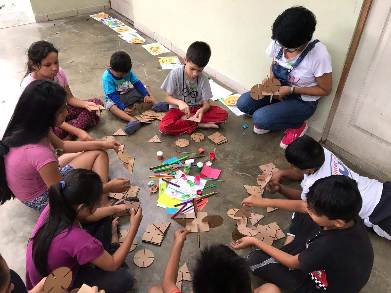
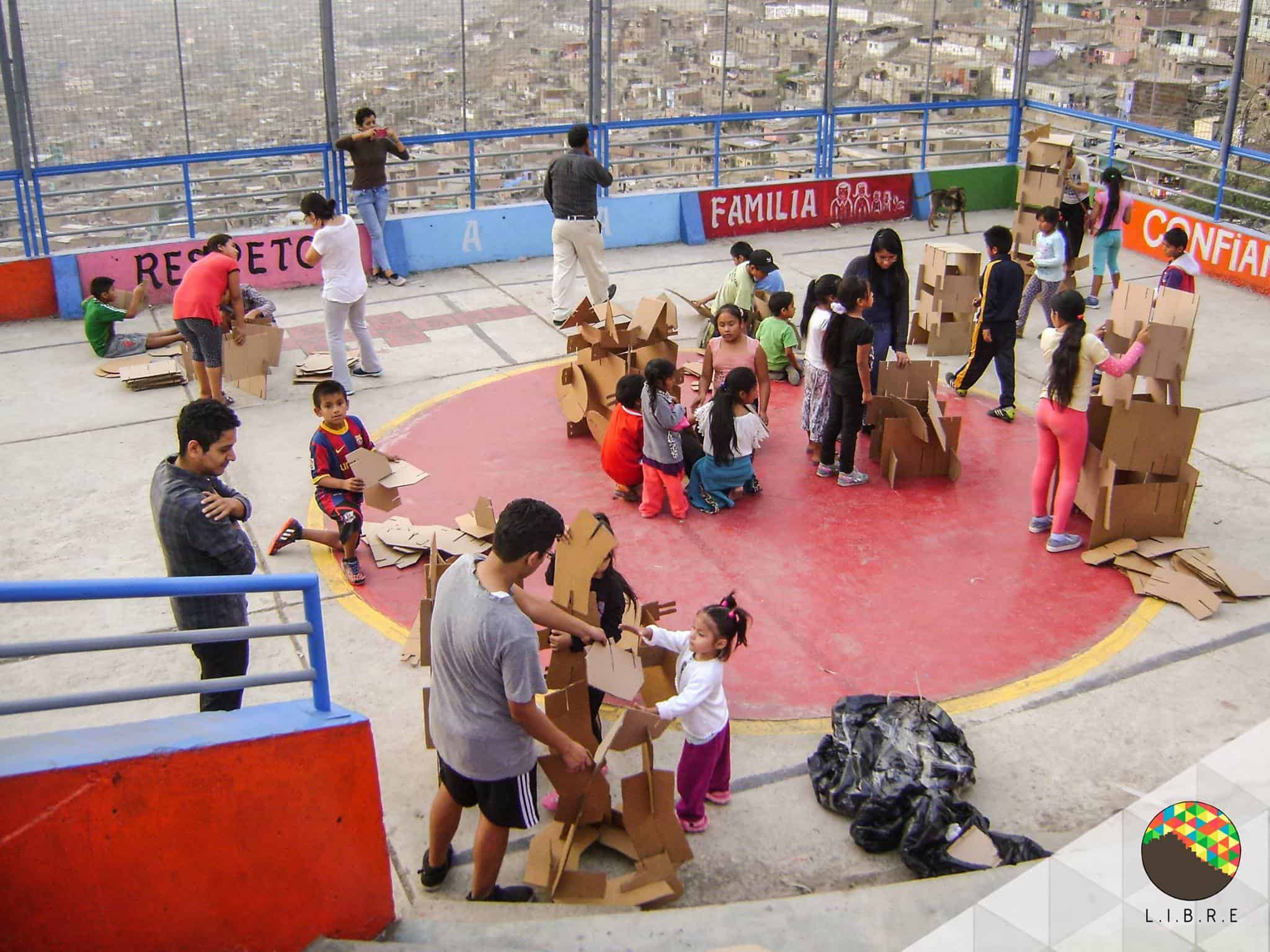
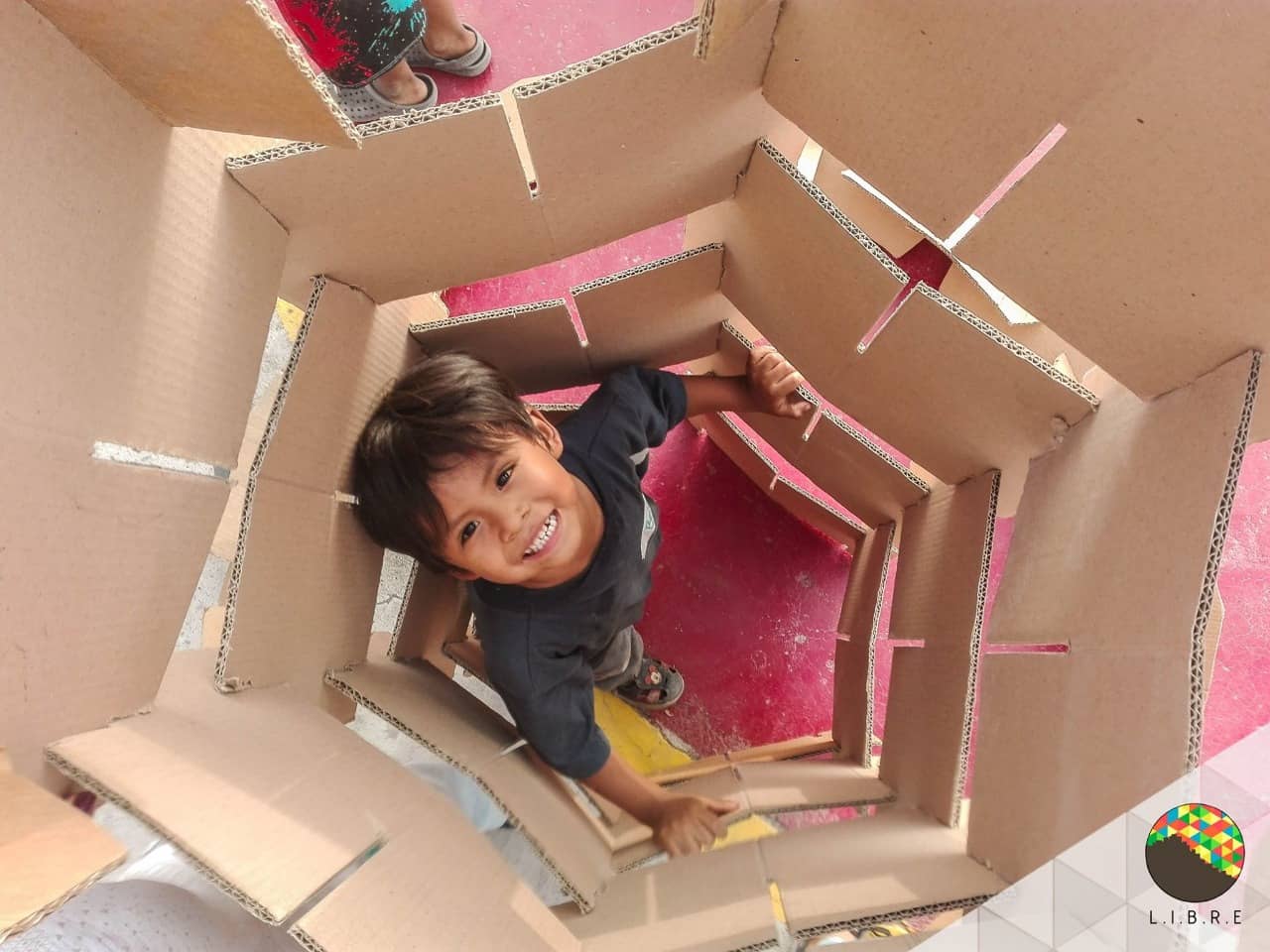
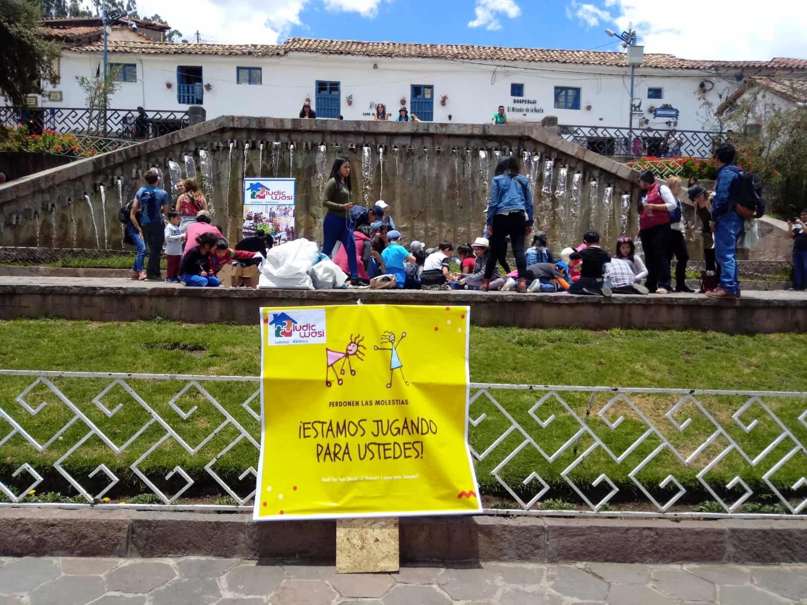
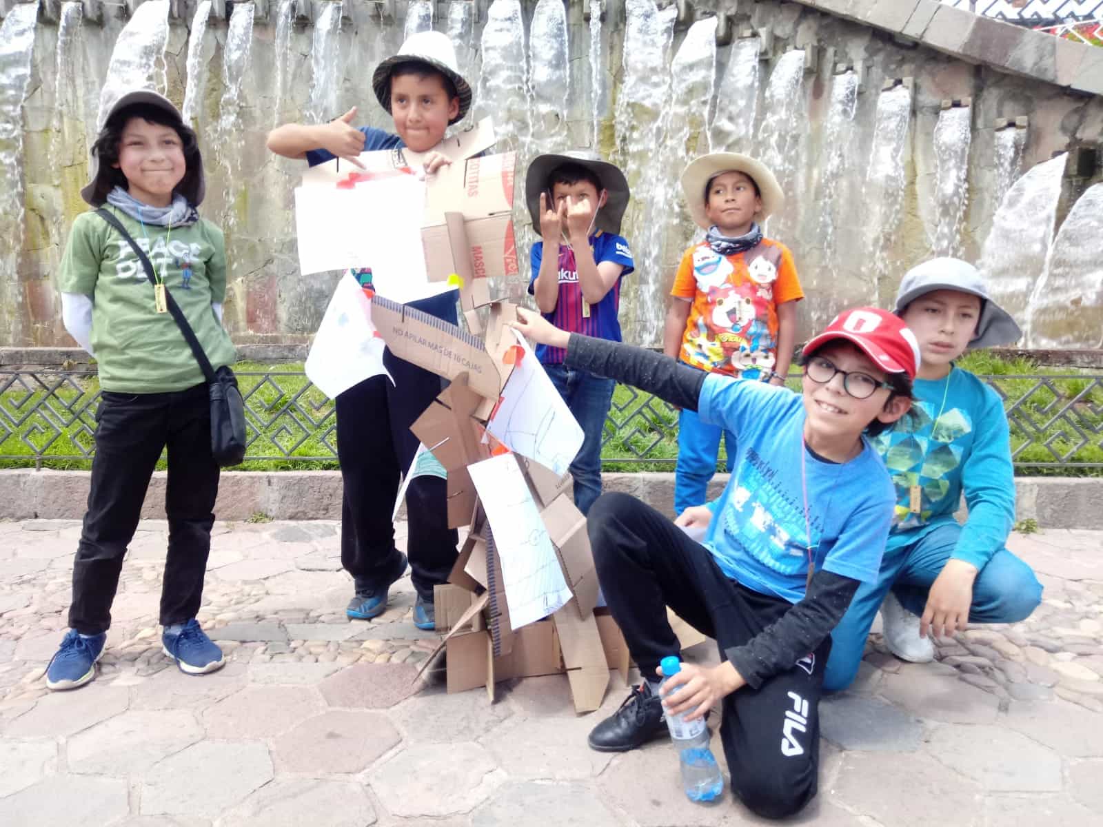
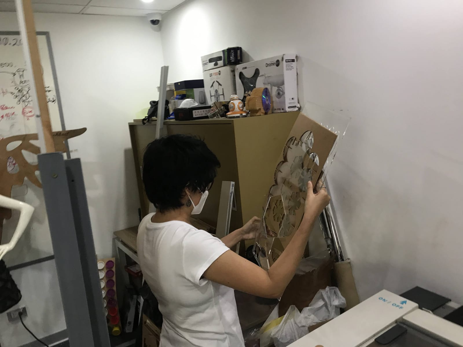
Another thing I got from returning to the
Fab Lab was to look at my previous work, when I was doing my
educational workshops I was using part formats for the children to build their own creations. 😍 These were a lot of fun for them and simple enough to get them to work on their imagination, so I started using the laser cutter, giving them a purpose to use the parts designed in Rhino. 💪 What I liked most about these formats was that I could make them to any scale, the bigger the kids got the
more fun they had. 😃
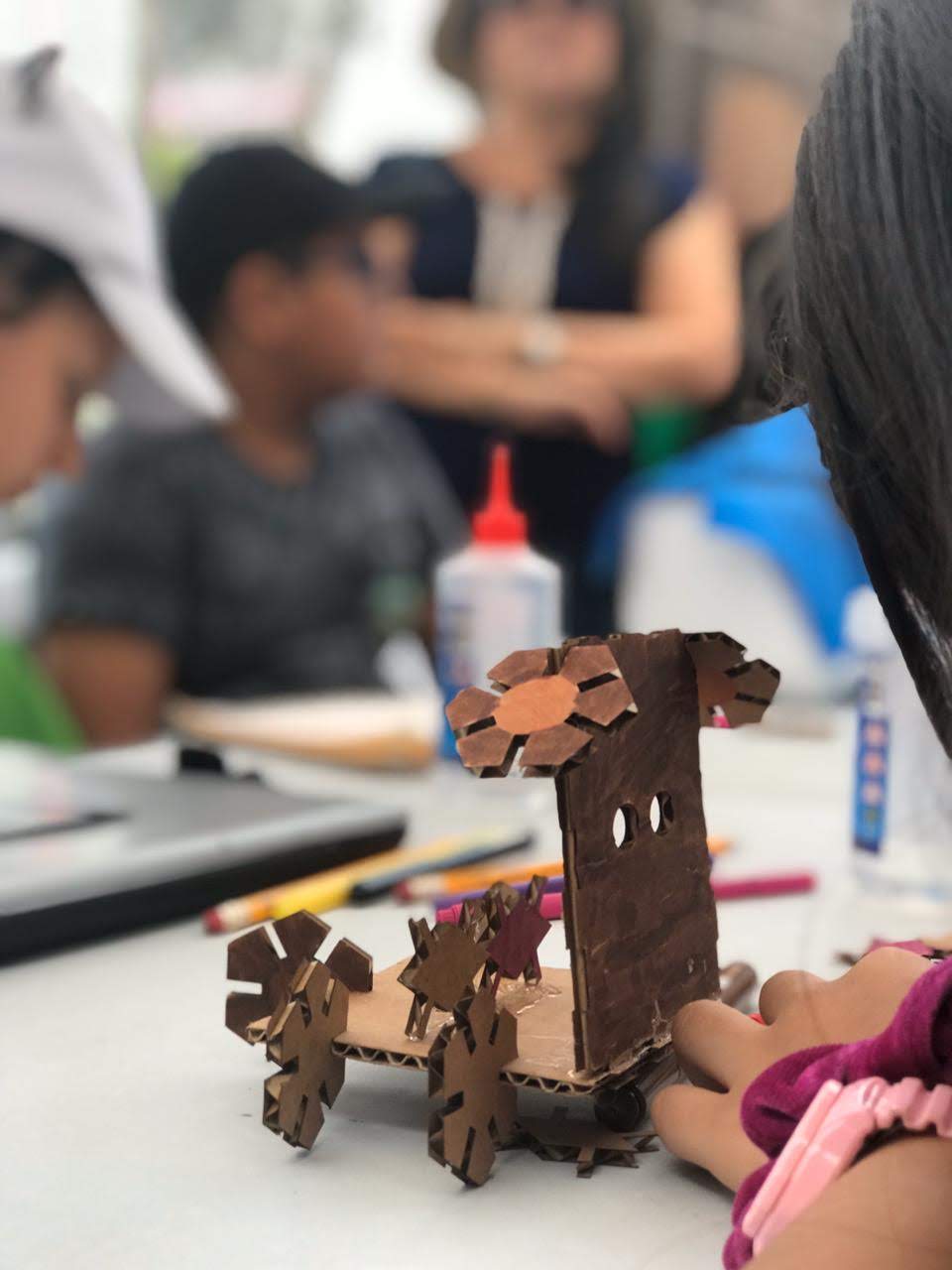
Pieces designed for my workshops
Pieces designed for my workshops
Pieces designed for my workshops
Workshop in Chorrillos - Lima
Workshop in El Agustino - Lima
Workshop in El Agustino - Lima
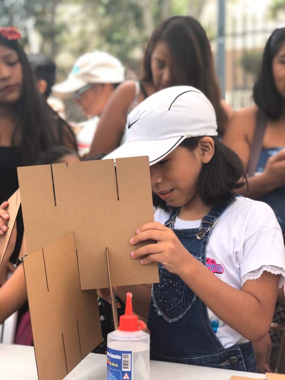
Workshop in "International day of girls and women in science"
Workshop in "International day of girls and women in science"