14. Networking and communications
Amsterdam, May 6, 2020
To do
| Description | status |
|---|---|
| Design ESP2866 | done |
| Mill, solder ESP2866 device | done unsuccessfully |
| Program board | board was dead on arrival |
| Mill and solder ESP32 Barduino board | done |
| Program ESP32 board Barduino | done |
| Design, mill and solder ESP32 board | done |
| Program ESP32 board | done |
| Make mesh network with my device + two other devices | done |
| Understand adding battery to devices | done |
| Understand I2C | done |
| Understand Painless Mesh | done |
| Connect OLED board with ESP2866 board | done |
| Connect OLED board with ESP32 board | done |
| Program ESP32 board to display on OLED monitor | done |
Source files
| Description | link |
|---|---|
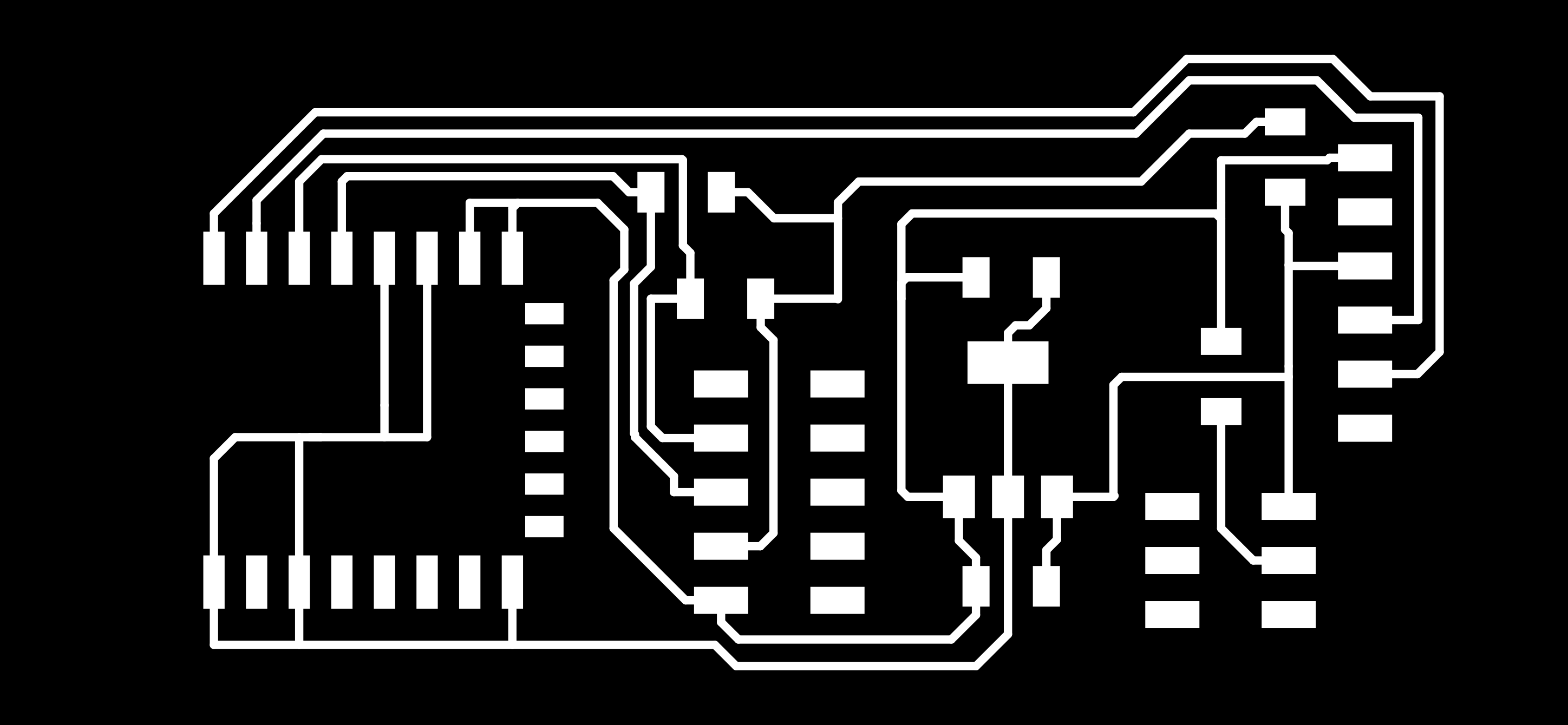
| ESP-12F version 1 with mistakes board traces | Downloadable PNG |
| ESP-12F version 1 with mistakes cuts | Downloadable PNG |
| KiCad ESP-12F version 1 with mistakes Eschema and PCBnew | Downloadable zip |
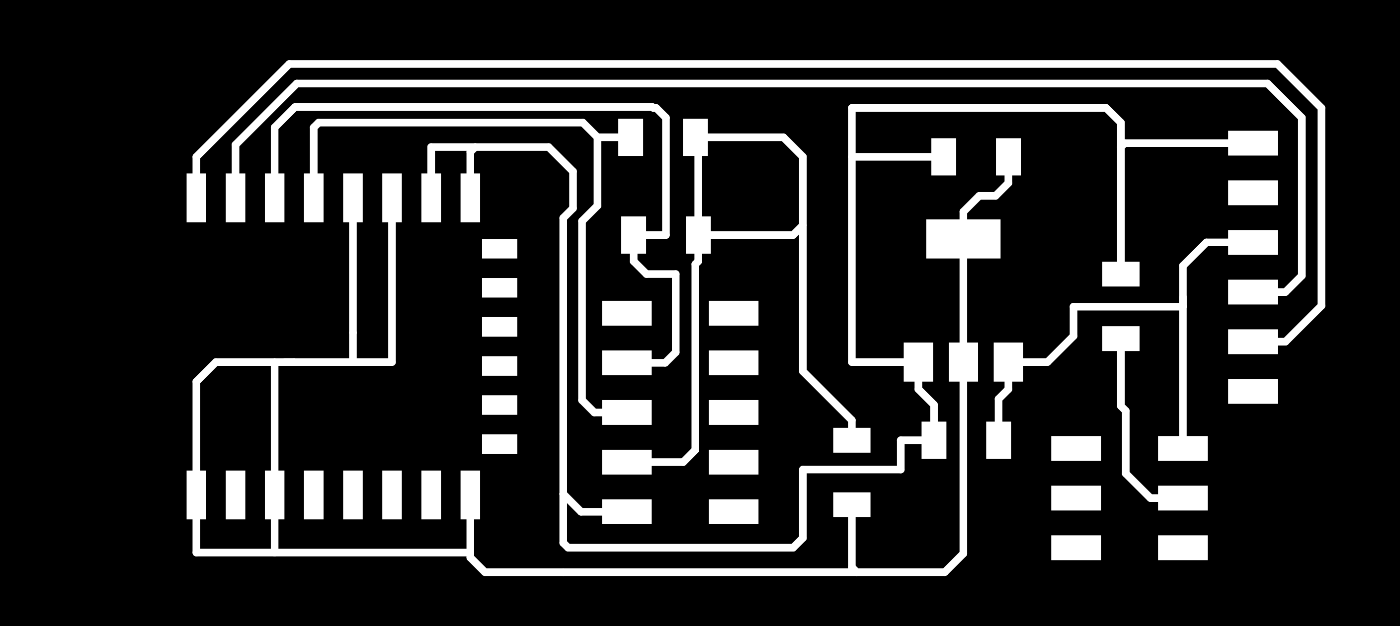
| ESP-12F version 2 board traces | Downloadable PNG |
| ESP-12F version 2 cuts | Downloadable PNG |
| KiCad ESP-12F version 2 Eschema and PCBnew | Downloadable zip |
| Barduino files original | Downloadable zip |
| Barduino files Hyejin’s adjustments | Downloadable zip |
| KiCad ESP32 project | Downloadable zip |
| KiCad fab library with ESP32 included | Downloadable zip |
| Code for ESP32 using touchpins and painlessMesh | Downloadable zip |
| Code for ESP32: mesh network, touchpins and oled monitor | Downloadable zip |
urls
| Description | link |
|---|---|
| Index of this week’s topic | http://academy.cba.mit.edu/classes/networking_communications/index.html |
| Global lecture video | https://vimeo.com/415632350 |
| Global review video | https://vimeo.com/418152082 |
| Group assignment | https://fabacademy.org/2020/labs/waag/groupAssignments/week14.html |
| Arduino ESP8266 library | https://github.com/esp8266/Arduino |
| Arduino ESP8266 forum | https://www.esp8266.com/viewforum.php?f=25 |
| ESP8266 core documentation | https://arduino-esp8266.readthedocs.io/en/latest/ |
| ESP family comparison table | https://www.esp8266.com/wiki/doku.php?id=esp8266-module-family |
Bread board set up
Henk gave me several ESP modules to try out.
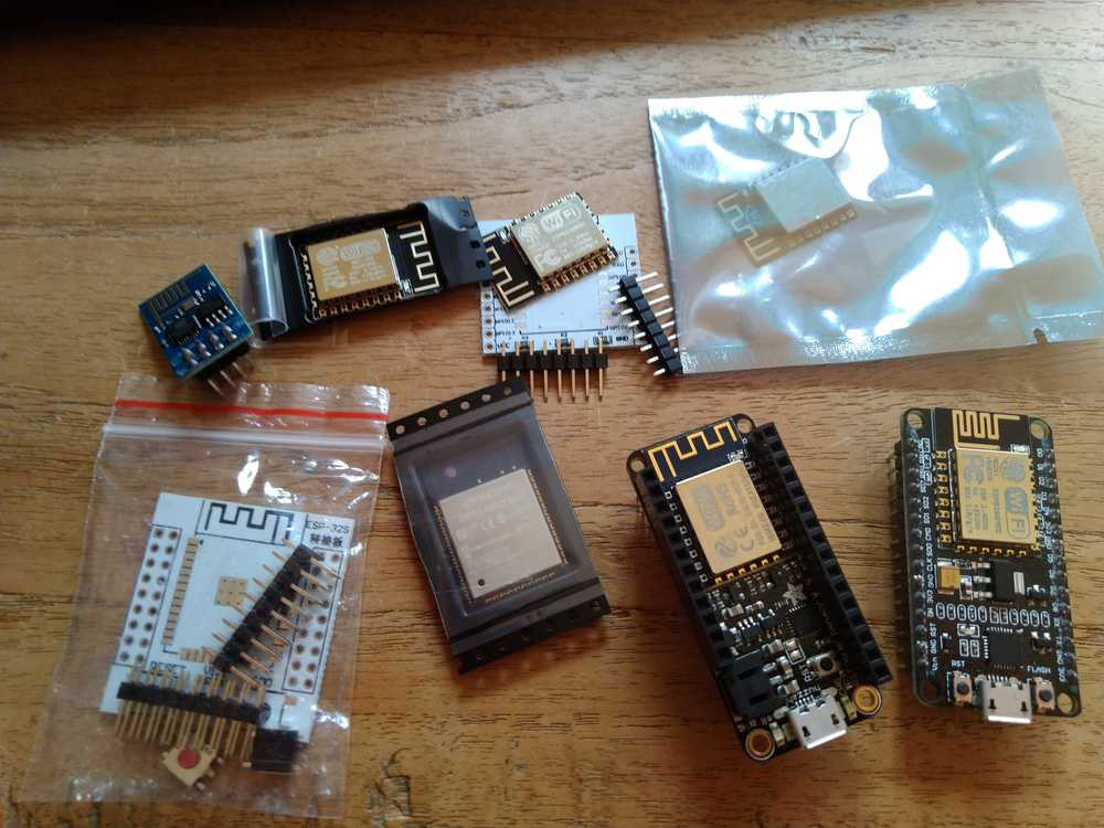
From left to right upper row: ESP8266-01, ESP-12F, ESP8266MOD & breadboard, ESP14.
Lower row: breadboard for the ESP32, ESP32, a Featherboard with a ESP-F module and a NodeMCU board with a ESP8266MOD module on it.
The ESP01 is the oldest and the simplest iteration of the ESP family. It has 8 pins sticking from the board. It is said it is really hard to program. The ESP-12F is a newer iteration, it is more powerful. I haven’t loked into the ESP-14. The ESP32 is a new generation ESP. It is more powerful, has more features like Bluetooth but it also consumes more power.
My initial plan was to make a breadboard setup and try the different modules. This is more labor intensive than I anticipated. It is not plug and play. Instead you need to solder the modules on the bread board and attach wires to them. Here are two tutorials showing how to do it. This is the better one: Solder breakout board and How to make your ESP12 breadboard friendly.
The problem is that the ESP modules need 3.3V. Both tutorials use a breadboard power supply that can be set to 3.3V. I don’t have that. There are ways to make your own regulated power supply for the breadboard as explained in this tutorial, this Instructables and another one. This is the simplest setup and used for the ESP01. I have all the components accept for the voltage regulators and the capacitors.
I made a list of components I would need to make the breadboard setup:
With breadboard power regulator
| component | quantity |
|---|---|
| Power supply AMS1117-5V & 3.3V, 800mA | 1 |
| USB-to-serial converter board 3.3V compatible | 1 |
Without power regulator
| component | quantity |
|---|---|
| USB-to-serial converter board 3.3V compatible | 1 |
| 3.3V power regulator with bread board compatible packaging | 1 |
| capacitors: different tutorials list different values for the capacitors. Mentioned are: 1uf, 10 uf, 100uf, 47 uf, 0.1 uf | quantity varies between 1 and 2 |
I don’t have these components at home, so I can’t do the breadboard setup. I was hoping to use the breadboard to test how the different modules compare with each other. Additionally, I wanted to test the circuit layout before finalizing the design for the board. Now that I can’t do the breadboard setup, I’ll go and do this theoretically rather than hands-on.
You could do a breadboard setup with the ESP-01 and an Arduino. See this student’s example.
So instead of breadboarding, I’ll go on to design the ESP-12F board. I’ll describe that below. But first I’ll look into voltage regulators and power supplies.
Voltage regulators
As I said,the ESPs all can’t handle 5V. They need 3.3V instead. When designing your own board you need to add a voltage regulator.
Am trying to find out how to regulate power on the board. There are voltage regulators. These regulate the voltage on the board. So you can input 5V but the regulator will regulate it to 3.3V before it flows to the ESP module.
A DroneBot workshop tutorial goes into voltage regulators and converters. Some takeaways:
Volt margin is stringent. For 5V project the marging is 4.75V - 5.25V. Too high can fry your components, too low can cause erratic operation.
6V 12V used for motors.
H-bridge on your circuit will make the voltage drop.
You may need different voltages in one project.
Power supplies:
AC comes from the wall outlet. Voltage needs to be brought down to level, for this level conversion is used: a transformer. After that AC is converted to DC, done with rectifyer or bridge rectifyer circuit. Finally voltage regulation makes sure to produce the correct outcome.
Battery is simpler. Linear voltage regulator: it takes a battery of a higher voltage level and passes it through a linear regulator.
Buck converter: battery of higher voltage is passed through buck converter to give regulated voltage at a lower level.
Boost converter: turns lower level battery output into higher level voltage.
Buck boost converter: can take its input voltage and make it both higher and lower.
Supplies to keep at hand:
3 pin linear voltage regulator. Different types.
Power supply unit: takes 220V in and outputs 5V.
USB breakouts: get 5V out of USB power supply.
Buck converter.
Bread board power supply.
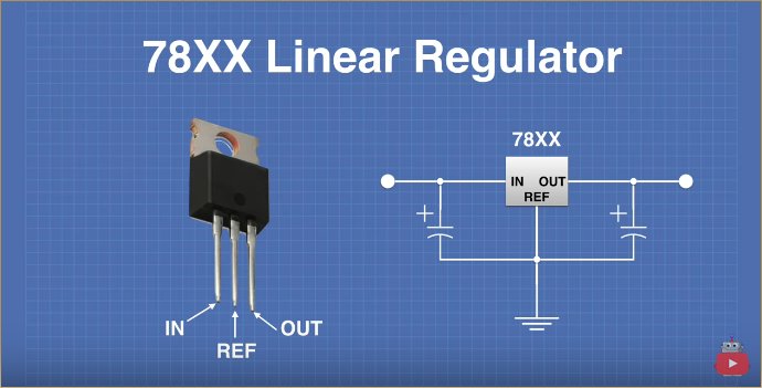
78xx series linear regulator
The 78xx series linear regulator. Three pin voltage regulator family. The ‘xx’ in the name indicates the output voltage. So 7805 = 5V. Available in different packages. Output capabilities of 1.5A.
Pinout is ismple: pin 1 = input. Pin 2 is reference pin, generally tied to GND. Pin 3 is the output. Easy to use, they require only two external components: small electrolytic capacitors. These are polarized. They do not need to have a specific value: tutor generally uses 2.2uF for input capcitor and 100uF for output capacitor.
Here is a picture of the schema:
Here is a picture of the setup in the tutorial:
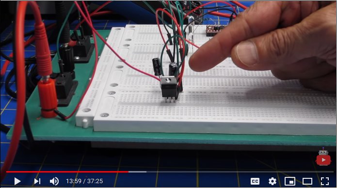
The input voltage is 9V, a multimeter measures the output at 5V. Left is pin 1, input. Right is pin 3, output. Pin 2 is grounded. 2.2uF capacitor at the input pin and 100uF capacitor on the output pin.
Top view:
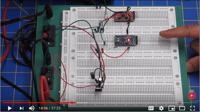
We see the voltage regulator powering up a little 3.3V Arduino pro mini.
LM317 linear regulator
The LM317 is a 3-pin Variable Positive Voltage Regulator. Output voltage can be set from 1.25V to 37V DC. You set the output voltage by setting two external resistors. Current up to 1.5A.
Pin out: pin 1 is the adjust pin, pin 2 is the putput, pin 3 is input. Resistors determine the voltage.
PSM-165 Linear module
This is a breakout board with a 3.3V linear regulator.
Input from 4.5V to 12V.
Up to 800mA of current.
Is used on the Arduino Uno.
It has 8 pins.
Trying ESP software with NodeMCU
I can’t make my board until Monday earliest, so I will try out software on the NodeMCU and the Feather, two dev boards with an integrated ESP. First just generally what works and then get the mesh networking to work.
I start with the NodeMCU which is an open-source IOT platform . developed for ESP8266 Wi-Fi Soc by Espressif Systems. Since it is open source the hardware designs are available. This could be interesting to get some ideas for my own ESP boards. ‘NodeMCU Dev Kit has Analog (i.e. A0) and Digital (D0-D8) pins on its board. It supports serial communication protocols i.e. UART, SPI, I2C etc.’ Source.
For development I am using the ArduinoIDE. I added the NodeMCU to the Arduino board manager during input week. There is package made by Ivan Grokhotkov that makes ESP8266 available for the Arduino IDE. The Arduino ESP2866 library does everything I want: using TCP, work with SD cards and SPI and I2C peripherals. And even there are more functionalities: ‘ESP8266 Arduino core comes with libraries to communicate over WiFi using TCP and UDP, set up HTTP, mDNS, SSDP, and DNS servers, do OTA updates, use a file system in flash memory, and work with SD cards, servos, SPI and I2C peripherals.’
- There is an ESP community forum and a ESP wiki, tutorials etc. can be found at everythingESP.
To add it to the IDE:
Open the Preferences window.
- Add https://arduino.esp8266.com/stable/package_esp8266com_index.json to the Additional Board Manager URLs field. You can add multiple URLs, separating them with commas.
- Open Boards Manager from Tools > Board menu and install esp8266 platform (and don’t forget to select your ESP8266 board from Tools > Board menu after installation).
- Open the boards manager under Tools.
- Type ESP and find the ESP library made by the ESP community.
- After installing the board go to Tool > Board and select NodeMCU 1.0 (ESP-12E module)
- Find the right port with python3 -m serial.tools.list_ports and select it under Tools > Port.
- Under Tools > Progammer ArduinoISP works
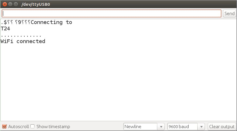
The first thing I do is a simple tutorial to connect the Node to a Wifi network and output it on the serial monitor.
#include <ESP8266WiFi.h>

const char *ssid =  "T24";     // replace with your wifi ssid and wpa2 key
const char *pass =  "Your_Password";

WiFiClient client;

void setup()
{
       Serial.begin(9600);
       delay(10);

       Serial.println("Connecting to ");
       Serial.println(ssid);

       WiFi.begin(ssid, pass);
       while (WiFi.status() != WL_CONNECTED)
          {
            delay(500);
            Serial.print(".");
          }
      Serial.println("");
      Serial.println("WiFi connected");
}

void loop()
{

}
Note that on the NodeMCU and I think ESP modules in general, you need to press the reset button after programming the board before the code will take effect. Arduino IDE warns of this as it prints Hard resetting via RTS pin... in the panel after programming.
I run the code and the serial monitor outputs:
I follow the great introduction on the NodeMCU from Electronicwings.com.
serial communication
A simple tutorial that has the Node output text to the serial port:
void setup()
{
Serial.begin(9600);  /* initialise serial communication */
}

void loop()
{
Serial.println("Post-collapse-networking"); /* print Electronic Wings at new line per second */
delay(1000);
}
Pins of the NodeMCU
Continuing the Electronicwings tutorial I look at the pinout of the NodeMCU. The General Purpose Input Output (GPIO) pins have different names on the Node than on the ESP-module. They correspond as follows:
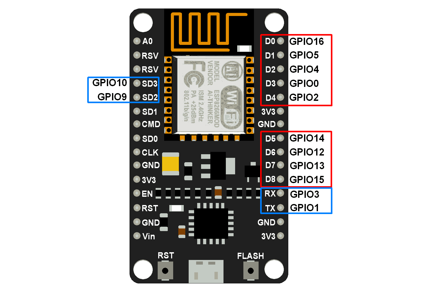
‘The GPIO’s shown in blue box (1, 3, 9, 10) are mostly not used for GPIO purpose on Dev Kit. The processor has around 16 GPIO lines, some of which are used internally to interface with other components of the SoC, like flash memory. Since several lines are used internally within the ESP8266 SoC, we have about 11 GPIO pins remaining for GPIO purpose. Now again 2 pins out of 11 are generally reserved for RX and TX in order to communicate with a host PC from which compiled object code is downloaded. Hence finally, this leaves just 9 general purpose I/O pins i.e. D0 to D8.’
Blink LED
uint8_t LED_Pin = D4;       // declare LED pin on NodeMCU Dev Kit

void setup() {
pinMode(LED_Pin, OUTPUT);   // Initialize the LED pin as an output
}

void loop() {
digitalWrite(LED_Pin, LOW); // Turn the LED on
delay(1000);                // Wait for a second
digitalWrite(LED_Pin, HIGH);// Turn the LED off
delay(1000);                // Wait for a second
}
Analog Digital Converter (ADC)
The ESP2866 has a 10-bit ADC with only one ADC channel. That means it only has one ADC input pin to read analog voltage from an external device. It ca measure onboard voltage or that of an external device. The range is 0 - 1.0V for reading external voltage.
ESP.getVcc() will read the internal voltage of the NodeMCU. The pin must be unconnected for it to work.
Tutorial: ‘Note that ADC mode should be changed to read system voltage before reading VCC supply voltage. To change ADC mode use ADC_MODE(mode) just after #include lines of your sketch. Modes are ADC_TOUT (for external voltage), ADC_VCC (for system voltage). By default, it reads external voltage.’
As per the example I hook up a potentiometer to the NodeMCU to adjust voltage and with the example code the serial monitor puts out the internal voltage.
void setup() {
  Serial.begin(9600);
}

void loop() {
  Serial.print("ADC Value: ");Serial.println(analogRead(A0));
  delay(300);
}
Pulse Width Modulation (PWM)
Still continuing the tutorial: ‘Pulse Width Modulation (PWM) is a technique by which width of a pulse is varied while keeping the frequency of the wave constant. A period of a pulse consists of an ON cycle (VCC) and an OFF cycle (GND). The fraction for which the signal is ON over a period is known as a duty cycle.
‘Duty cycle percentage formula: DutyCycle% = T on / TotalPerion * 100. E.g. A pulse with a period of 10ms will remain ON (high) for 2ms.Therefore, duty cycle will be: D = 2ms / 10ms = 20%.
‘Through PWM technique, we can control the power delivered to the load by using ON-OFF signal. The PWM signals can be used to control the speed of DC motors and to change the intensity of the LED. Moreover, it can also be used to generate sine signals. Pulse Width Modulated signals with different duty cycle are shown below.’
The NodeMCU has 9 pins that can do PWM.
GPIO Interrupts
Tutorial: ‘An interrupt is an event that occurs randomly in the flow of continuity. It is just like a call you have when you are busy with some work and depending upon call priority you decide whether to attend or neglect it.’ There is example code here should I need it.
I2C
I know I2C from working with the OLED monitor. I would like to add it to my board. Tutorial: ‘I2C is acknowledgment based communication protocol i.e. transmitter checks for an acknowledgment from the receiver after transmitting data to know whether data is received by receiver successfully. I2C works in two modes: parent mode and child mode. SDA (serial data) wire is used for data exchange in between parent and child device. SCL (serial clock) is used for the synchronous clock in between parent and child device.’ Henk explained about the clock this week, it regulates the timing of the bits so you don’t need to have a hardwared data rate protocol between devices.
The parent device requires an address from the child device to start communication. Not all pins on the NodeMCU can be used as SDA/SCL pins.
The tutorial gives a setup in which the Arduino Uno is the child device addressed and the NodeMCU the parent. The output on the serial monitor of the child device is Hello Arduino, on the port of the Node it’s Hello NodeMCU.
Code for the child device:
#include <Wire.h>

void setup() {
 Wire.begin(8);                /* join i2c bus with address 8 */
 Wire.onReceive(receiveEvent); /* register receive event */
 Wire.onRequest(requestEvent); /* register request event */
 Serial.begin(9600);           /* start serial for debug */
}

void loop() {
 delay(100);
}

// function that executes whenever data is received from parent
void receiveEvent(int howMany) {
 while (0 <Wire.available()) {
    char c = Wire.read();      /* receive byte as a character */
    Serial.print(c);           /* print the character */
  }
 Serial.println();             /* to newline */
}

// function that executes whenever data is requested from parent
void requestEvent() {
 Wire.write("Hello NodeMCU");  /*send string on request */
}
Code for parent device
#include <Wire.h>

void setup() {
 Serial.begin(9600); /* begin serial for debug */
 Wire.begin(D1, D2); /* join i2c bus with SDA=D1 and SCL=D2 of NodeMCU */
}

void loop() {
 Wire.beginTransmission(8); /* begin with device address 8 */
 Wire.write("Hello Arduino");  /* sends hello string */
 Wire.endTransmission();    /* stop transmitting */

 Wire.requestFrom(8, 13); /* request & read data of size 13 from child */
 while(Wire.available()){
    char c = Wire.read();
  Serial.print(c);
 }
 Serial.println();
 delay(1000);
}
It works. And this is very close to what I want to do on my final project. So I would like my ESP board to talk to my OLED board over I2C. Questions:
- How do I wire up the NodeMCU to my OLED board. It does not have a GND pin sticking out.
- The OLED board needs to be conected to USB port via FTDI to get power. It should get its own power supply.
I might need to make a new OLED board with more capabilities like an GND pin you can connect to.
Mesh network: painlessMesh
Trying to create a mesh network with the NodeMCU and the Feather. I use the painless mesh library. Here is the GitLab home of painlessMesh. This library takes care of mesh networking. It is actively being developed. It uses JSON to handle data transfer. Important to know is that you can’t use the delay function in your code because that will disrupt the mesh networking processes.
Sketch > Include library > manage libraries search for painless mesh. It’ll tell you additional libraries need to be installed. Install all.
I had to add the ESPAsynTCP.h library by adding library by zip.
From the example code in the Painlesh Mesh library I make the two nodes talk to each other. Don’t forget to press the reset button after installation.
For all PainlessMesh code the WiFi credentials must be the same for all nodes in the network. The standard WiFi credentials in all the example code is like this.
#define   MESH_PREFIX     "whateverYouLike"
#define   MESH_PASSWORD   "somethingSneaky"
#define   MESH_PORT       5555
//************************************************************
// this is a simple example that uses the painlessMesh library
//
// 1. sends a silly message to every node on the mesh at a random time between 1 and 5 seconds
// 2. prints anything it receives to Serial.print
//
//
//************************************************************
#include "painlessMesh.h"
#define MESH_PREFIX "post-collapse"
#define MESH_PASSWORD "networking"
#define MESH_PORT 5555
Scheduler userScheduler; // to control your personal task
painlessMesh mesh;
// User stub
void sendMessage() ; // Prototype so PlatformIO doesn't complain
Task taskSendMessage( TASK_SECOND * 1 , TASK_FOREVER, &sendMessage );
void sendMessage() {
String msg = "Hello from node ";
msg += mesh.getNodeId();
mesh.sendBroadcast( msg );
taskSendMessage.setInterval( random( TASK_SECOND * 1, TASK_SECOND * 5 ));
}
// Needed for painless library
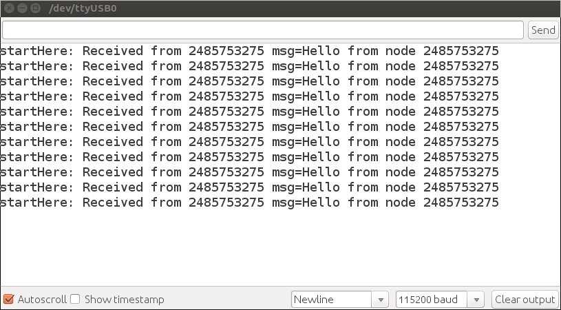
void receivedCallback( uint32_t from, String &msg ) {
Serial.printf("startHere: Received from %u msg=%s\n", from, msg.c_str());
}
void newConnectionCallback(uint32_t nodeId) {
Serial.printf("--> startHere: New Connection, nodeId = %u\n", nodeId);
}
void changedConnectionCallback() {
Serial.printf("Changed connections\n");
}
void nodeTimeAdjustedCallback(int32_t offset) {
Serial.printf("Adjusted time %u. Offset = %d\n", mesh.getNodeTime(),offset);
}
void setup() {
Serial.begin(115200);
//mesh.setDebugMsgTypes( ERROR | MESH_STATUS | CONNECTION | SYNC | COMMUNICATION | GENERAL | MSG_TYPES | REMOTE ); // all types on
mesh.setDebugMsgTypes( ERROR | STARTUP ); // set before init() so that you can see startup messages
mesh.init( MESH_PREFIX, MESH_PASSWORD, &userScheduler, MESH_PORT );
mesh.onReceive(&receivedCallback);
mesh.onNewConnection(&newConnectionCallback);
mesh.onChangedConnections(&changedConnectionCallback);
mesh.onNodeTimeAdjusted(&nodeTimeAdjustedCallback);
userScheduler.addTask( taskSendMessage );
taskSendMessage.enable();
}
void loop() {
// it will run the user scheduler as well
mesh.update();
}
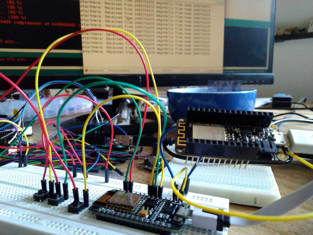
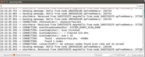
Front NodeMCU, back Feather, way in the back the output on the serial monitor.
Output on serial monitor
NodeMCU & monitor
I look at this Instructables tutorial. And from here I use the wiring setup and code to make the OLED monitor display something. It works, kinda.
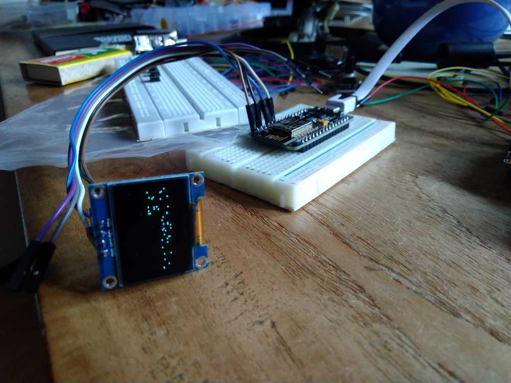
The pinout is:
| Oled pin | NodeMCU pin | ESP8266 pin |
|---|---|---|
| VCC | 3.3V | VCC |
| GND | GND | GND |
| SDA | D2 | GPIO5 |
| SCL | D1 | GPIO 4 |
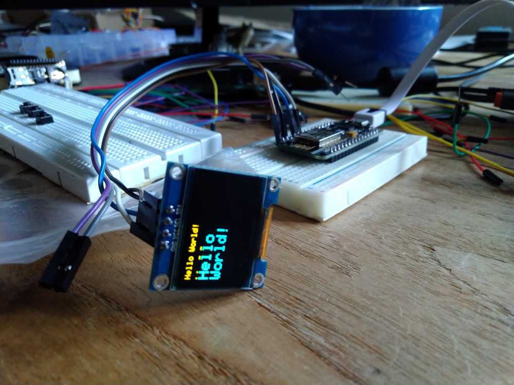
This code works better
//For more hardware details, visit https://iotforgeeks.com/interface-i2c-oled-display-ssd1306-with-nodemcu

#include <Wire.h>
#include <Adafruit_GFX.h>
#include <Adafruit_SSD1306.h>

#define SCREEN_WIDTH 128 // OLED display width, in pixels
#define SCREEN_HEIGHT 64 // OLED display height, in pixels
#define OLED_ADDR 0x3C   // Address may be different for your module, also try with 0x3D if this doesn't work

// Declaration for an SSD1306 display connected to I2C (SDA, SCL pins)
#define OLED_RESET -1 // Reset pin # (or -1 if sharing Arduino reset pin)
Adafruit_SSD1306 display(SCREEN_WIDTH, SCREEN_HEIGHT, &Wire, OLED_RESET);
//For more hardware details, visit https://iotforgeeks.com/interface-i2c-oled-display-ssd1306-with-nodemcu

void setup() {
  Serial.begin(9600);
  display.begin(SSD1306_SWITCHCAPVCC, OLED_ADDR);
  display.clearDisplay();           // Required to clear display
  display.display();

  display.setTextColor(WHITE);
  display.setTextSize(1);           // Set text size
  display.print("Hello World!");

  display.setTextSize(2);
  display.setCursor(0, 15);         // Set cursor
  display.print("Hello");
  display.setCursor(0, 32);
  display.print("World!");


  display.display();                // Always required when changes are made and when you have to display them
  while(1) delay(50);

}

void loop() {
}
I want the NodeMCU to output the messages from the other node to the monitor instead of the serial monitor.
I combine the OLED code and the NodeEcho code. At least the code isn’t broken. It compiles and it uploads. The Feather is still outputting messages on the serial monitor, so it appears the mesh networking is still working on both nodes. However, the oled displays ‘hello world’ and not the incoming messages from the Feather node.
//************************************************************
// this is a simple example that uses the painlessMesh library
//
// 1. sends a silly message to every node on the mesh at a random time between 1 and 5 seconds
// 2. prints anything it receives to Serial.print
//
//
//************************************************************

#include "painlessMesh.h"
#include <Wire.h>
#include <Adafruit_GFX.h>
#include <Adafruit_SSD1306.h>

#define   MESH_PREFIX     "post-collapse"
#define   MESH_PASSWORD   "networking"
#define   MESH_PORT       5555

#define SCREEN_WIDTH 128 // OLED display width, in pixels
#define SCREEN_HEIGHT 64 // OLED display height, in pixels
#define OLED_ADDR 0x3C   // Address may be different for your module, also try with 0x3D if this doesn't work
#define OLED_RESET -1 // Reset pin # (or -1 if sharing Arduino reset pin)
Adafruit_SSD1306 display(SCREEN_WIDTH, SCREEN_HEIGHT, &Wire, OLED_RESET);

Scheduler userScheduler; // to control your personal task
painlessMesh  mesh;

// User stub
void sendMessage() ; // Prototype so PlatformIO doesn't complain

Task taskSendMessage( TASK_SECOND * 1 , TASK_FOREVER, &sendMessage );

void sendMessage() {
  String msg = "Hello from node ";
  msg += mesh.getNodeId();
  mesh.sendBroadcast( msg );
  taskSendMessage.setInterval( random( TASK_SECOND * 1, TASK_SECOND * 5 ));
}

// Needed for painless library
void receivedCallback( uint32_t from, String &msg ) {
  Serial.printf("startHere: Received from %u msg=%s\n", from, msg.c_str());
}

void newConnectionCallback(uint32_t nodeId) {
    Serial.printf("--> startHere: New Connection, nodeId = %u\n", nodeId);
}

void changedConnectionCallback() {
  Serial.printf("Changed connections\n");
}

void nodeTimeAdjustedCallback(int32_t offset) {
    display.printf("Adjusted time %u. Offset = %d\n", mesh.getNodeTime(),offset);
}

void setup() {
    display.begin(SSD1306_SWITCHCAPVCC, OLED_ADDR);
  display.clearDisplay();           // Required to clear display
  display.display();

  display.setTextColor(WHITE);
  display.setTextSize(1);           // Set text size
  display.print("Hello World!");
   display.display();

//mesh.setDebugMsgTypes( ERROR | MESH_STATUS | CONNECTION | SYNC | COMMUNICATION | GENERAL | MSG_TYPES | REMOTE ); // all types on
  mesh.setDebugMsgTypes( ERROR | STARTUP );  // set before init() so that you can see startup messages

  mesh.init( MESH_PREFIX, MESH_PASSWORD, &userScheduler, MESH_PORT );
  mesh.onReceive(&receivedCallback);
  mesh.onNewConnection(&newConnectionCallback);
  mesh.onChangedConnections(&changedConnectionCallback);
  mesh.onNodeTimeAdjusted(&nodeTimeAdjustedCallback);

  userScheduler.addTask( taskSendMessage );
  taskSendMessage.enable();


}

void loop() {
  // it will run the user scheduler as well
  mesh.update();
}
Arduino coding
I started a Tutorial from Derek Banas. Here are some takeaways:
const = constant, valid for all functions. Global value, accessible to all code in the program. Don’t use to many
void setup / void loop = functions
const int = constant integer. Integer because we store a value inside of it.
const int ledPin = 13; = define ledpin is 13.
void setup = to initialize.
Serial.begin(9600) talk to serial monitor at 9600 baudrate.
pinMode(ledPin) Here you are referencing the pin
pinMode(ledPin, OUTPUT); Use it for output.
void loop() { //loops forever
int // create local variable. define another integer.
}
Sparkfun integer is a datatype. Computer does not know what you mean by numbers. You must tell the compiler that. There are different datatypes. Signed variables allow both positive and negative numbers, while unsigned variables allow only positive values.
Integer is a signed number
Designing the ESP-12F board
Here are Neil’s example of the ESP-12E board and components. And an example of fabstudent 2017 Cesar Mariscal and another with polarized capacitors from Moath Momani from 2018.
I will add two 4-header 10-header pins because I want to add two I2C capabilities. I am going to use the 10-header pin because I want the I2C pins to be in a need row and not in a square. Because that will probably cause confusion down the line. There need to be resistors between SDA and SCL pins of peripheral an chip.
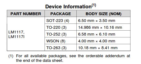
Footprint LM1117
Finding footprint for the voltage regulator LM1117. The Kicad forum refered to a specific footprint library. It should be one of these: SOT-223, TO-220, TO-252, TO-263.
If you want to see the footprints without having to load them into PCB new go to the general workbench, open footprint editor, double click on a library, double click on a footprint.
I don’t know which voltage regulator we have at the lab, so I do not know which footprint to use. There are four types of footprints according to the datasheet
In the FabLab inventory list I see under regulators:
LM3480IM3-3.3/NOPBCT-ND IC 3.3V100MA LDO VREG SOT23-
576-1259-1-ND IC REG LINEAR 3.3V 150MA SOT23-5
So I’ll assume I need the SOT23 or the SOT23-5 footprint. The -5 has 5 pads, the SOT23 is too small.
I try the next regulators on the list:
ZLDO1117G33DICT-ND IC REG LDO 3.3V 1A SOT223-3
NCP1117ST50T3GOSCT-ND IC REG LDO 5V 1A SOT223-3
SOT223-3 isn’t the same size as the examples either but it is the closest I have gotten. Without access to the lab and actually knowing which regulators we use, I can’t be sure.
Pinout
Here is a great explanantion of randomnerdtutorials about the pinout of the ESP-E. Here is their pinout schematic:
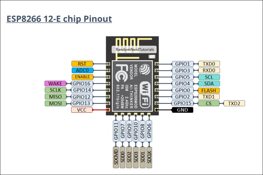
I2C
- So my I2C traces have to go to the GPIO4 and GPIO5 pins. I am reading up on learningaboutelectronics a bit on how to wire them up:
- ‘In order to work, the 2 lines of the I2C, the clock and data lines, need pull-up resistors to the positive voltage source.’
- I know this by now but I still going to note it down for my own reference.
- ‘When a command or request is sent out by the master device, it is received by all slave devices on the bus. Each I2C device has a unique 7-bit address, or ID number. When communication is initiated by the master device, a device ID is transmitted. I2C slave devices react to data on the bus only when it is drected at their ID number. Since all the devices are receiving all the data transmitted by the master device, each device has to have a unique ID number so that the master can speak to a particular slave device.’
There is also info here about the case in which two devices have the same hardwired I2C address. May need that later.
Also for reference: the code in this example use the wire.h library and the Serial.begin command to get communication going. In this example an Arduino talks to two sensors.
There need to be resistors between the SDA and SCL pins of the peripheral and the chip. In week11 I used 10k ohm resistors, in the above example they use 4.7k. Since one of the I2C capabilities is an open line for future purposes I could assign 2 different values.
Here is a datasheet on pullup resistors with I2C communications from Texas Instruments. It states that yes, the correct value is important. A wrong value can cause signal loss. But there is some serious math going on on that data sheet… Note to self, I can put a 4.7k resistor in my design now and always desolder and put in another one. Trial and error baby!
Later I read at Sparkfun ‘Resistor selection varies with devices on the bus, but a good rule of thumb is to start with 4.7k and adjust down if necessary. I2C is a fairly robust protocol, and can be used with short runs of wire (2-3m). For long runs, or systems with lots of devices, smaller resistors are better.’
Hmm, in the comments of this tutorial people say the resistor needs to be in between VCC and the SDA & SCL lines. Another explainers does it like that as well.
Here is the schematic of the tutorial above:
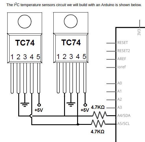
As you can see, VCC runs straight into the I2C peripheral. Then there is a resistor between SCL pin of the peripheral & of the chip. (Same for SDA.)
But this tutorial does something different: the resistor is placed between VCC and SCL line.
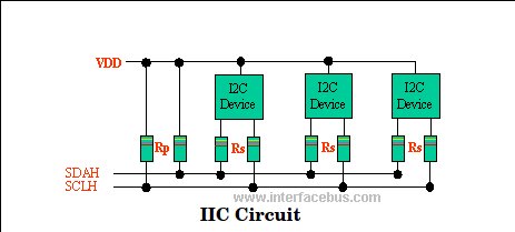
It states: ‘Both lines are pulled high via a resistor [Rp]. Resistor Rs is optional, and used for ESD protection for ‘Hot-Swap’ devices.’
I read in the datasheet that pullups are used to keep a device from floating. That is, if it is not in use it can have different currents flowing through it and device can’t decide whether it is HIGH or LOW. The pull resistor makes sure the device does not float but is either pulled to VCC with a pullup resistor, or pulled to GND with a pull down resistor.
- And again Sparkfun is very clear in its explanantions:
-
‘Unlike UART or SPI connections, the I2C bus drivers are “open drain”, meaning that they can pull the corresponding signal line low, but cannot drive it high. Thus, there can be no bus contention where one device is trying to drive the line high while another tries to pull it low, eliminating the potential for damage to the drivers or excessive power dissipation in the system. Each signal line has a pull-up resistor on it, to restore the signal to high when no device is asserting it low.’
Pullup pin: Still Sparkfun
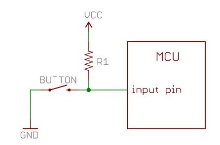
-
‘With a pull-up resistor, the input pin will read a high state when the button is not pressed. In other words, a small amount of current is flowing between VCC and the input pin (not to ground), thus the input pin reads close to VCC. When the button is pressed, it connects the input pin directly to ground. The current flows through the resistor to ground, thus the input pin reads a low state. Keep in mind, if the resistor wasn’t there, your button would connect VCC to ground, which is very bad and is also known as a short.’
So a pullup pin makes sure that in ‘normal state’ the peripheral reads HIGH. As Sparkfun explains, the I2C peripherals are ‘open drain’. They can not drive a line HIGH. They can only pull it LOW. If the peripherals want some attention from the parent, they pull the line LOW. Once that is done the pullup resistor pulls the line HIGH again. So line is HIGH unless a peripheral asserts otherwise.
Therefore I assume the pullup resistor must be between VCC and the peripheral. It makes sure the device stays HIGH, unless a specific event happens.
(June 10, 2020: I now know that this is indeed correct and the one from the contested tutorial notcorrect. I have now seen many schematics of I2C and the all place the pull-up resistors like.)
Independent power supply
I want to have the board be able to operate independently power-wise. So next to the FTDI that powers this board I also want to add a power supply. Here is a Sparkfun tutorial on adding batteries to your project. It prefer to go with AA batteries (2500 mAh NiMH Battery - AA) because they are ubiquitous and this project is about making things from stuff that is readily available.
I could use those little black battery holder boxes. You can just solder the wires on the board. But I prefer to have a proper connection. You can use a Barreljack adapter: female and male.
Connectors
Sparkfun tutorial on power connectors.
Terminology:
gender: (this terminology is jarring) pins or holes.
polarity: most connectors can only be connected in one orientation.
Contact: the conducing pins.
pitch: ‘Many connectors consist of an array of contacts in a repeated pattern. The pitch of the connector is the distance from the center of one contact to the center of the next. This is important, because there are many families of contacts which look very similar but may differ in pitch, making it difficult to know that you are purchasing the right mating connector.’‘
Mating cycles: (this terminology is really jarring). How often you can connect and disconnect.
Mount: ‘This one has the potential for being confusing. The term “mount” can refer to several things: how the connector is mounted in use (panel mount, free-hanging, board mount), what the angle of the connector is relative to its attachment (straight or right-angle), or how it is mechanically attached (solder tab, surface mount, through hole). We’ll discuss this more in the examples section for each individual connector.’
Barrel connectors
‘are typically found on low-cost consumer electronics which can be plugged into wall power via bulky AC wall adaptors. Wall adaptors are widely available, in a variety of power ratings and voltages, making barrel connectors a common means for connecting power to small projects.’
Molex Connectors
Often used in computers, designed to transfer a lot of current.
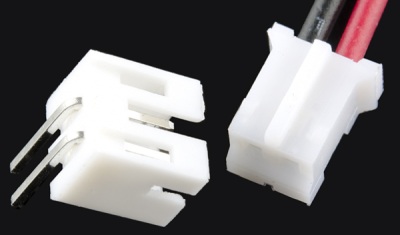
JST Connector
The well-known white plugs that are hard to disengage. Lithium-polymer ion batteries often come with these. Can they also be used for AA batteries? Yes you can! Adafruit sells AA batery packages with this connector and they probably know what they are doing.
Which battery to use Battery life or capacity is the measure of total charge the battery contains. It is measured in Ampere-hours (Ah) or milliampere-hours (mAh). It is the amount of amps a fully charged battery supplies for an hour. For example, a 2000mAh battery can supply up to 2A (2000mA) for one hour.
Source.
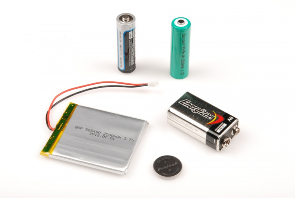
Starting at the top and going clockwise: AA Alkaline, AA Nickel Metal Hydride (NiMH), 9V Alkaline battery, Lithium coin cell battery, Lithium Polymer (LiPO).
Terminology: Source Sprakfun.
capacity: amount of power the battery can store.
nominal cell voltage: The average voltage a cell outputs when charged. Decreases when discharged.
Shape: the shape the battery comes in.
Primary vs secondary: disposable vs rechargeable.
Energy density: Lithium is more dense.
internal discharge rate: rate at which battery discharges when you don’t use it.
Lithium Polymer
Often used in DIY projects. Have a long life time. Require special charging so be aware. Only go up to 4.3V and 3.7V under normal use. So your project must be able to handle different voltages. If you need 5V you have to combine two LiPo’s and regulate 7.4V down to 5V. Uses JST connector.
Nickel Metal Hydride (NiMH)
Rechargable batteries. ‘Each cell outputs nominally 1.2V. This is very similar to alkaline batteries of the same size that output 1.5V. Combining four AA NiMH will get you a 4.8V pack which should run most 5V systems but will drop in voltage as the pack discharges.’
Alkaline These are the batteries we are all most familiar with. AAs and AAAs are the most common alkaline batteries and output 1.2V nominally (but are around 1.5V when first used). Because AAs output 1.2V, you will need to combine them in packs of 3 or 4 to run your 3.3V or 5V system. 9V batteries are obviously 9V nominally.
Batteries in Series and Parallel
Series: Source
Two components are in series if they share a common node (the wire between two components) and if the same current flows through them. Current flows from high (VCC) to low (GND) if it runs through the circuit in series, it can only flow in one way.
Parallel: If components share two common nodes, they are in parallel. The current meets a split in the road and can go two directions. If all bifurcations have the same resistor value, all paths result in the same drop voltage. But if resistors have different values, voltage drop will vary. So if we have 2mA flowing through the circuit and a biforcation that each has a 10k resistor, each path will have 1mA.
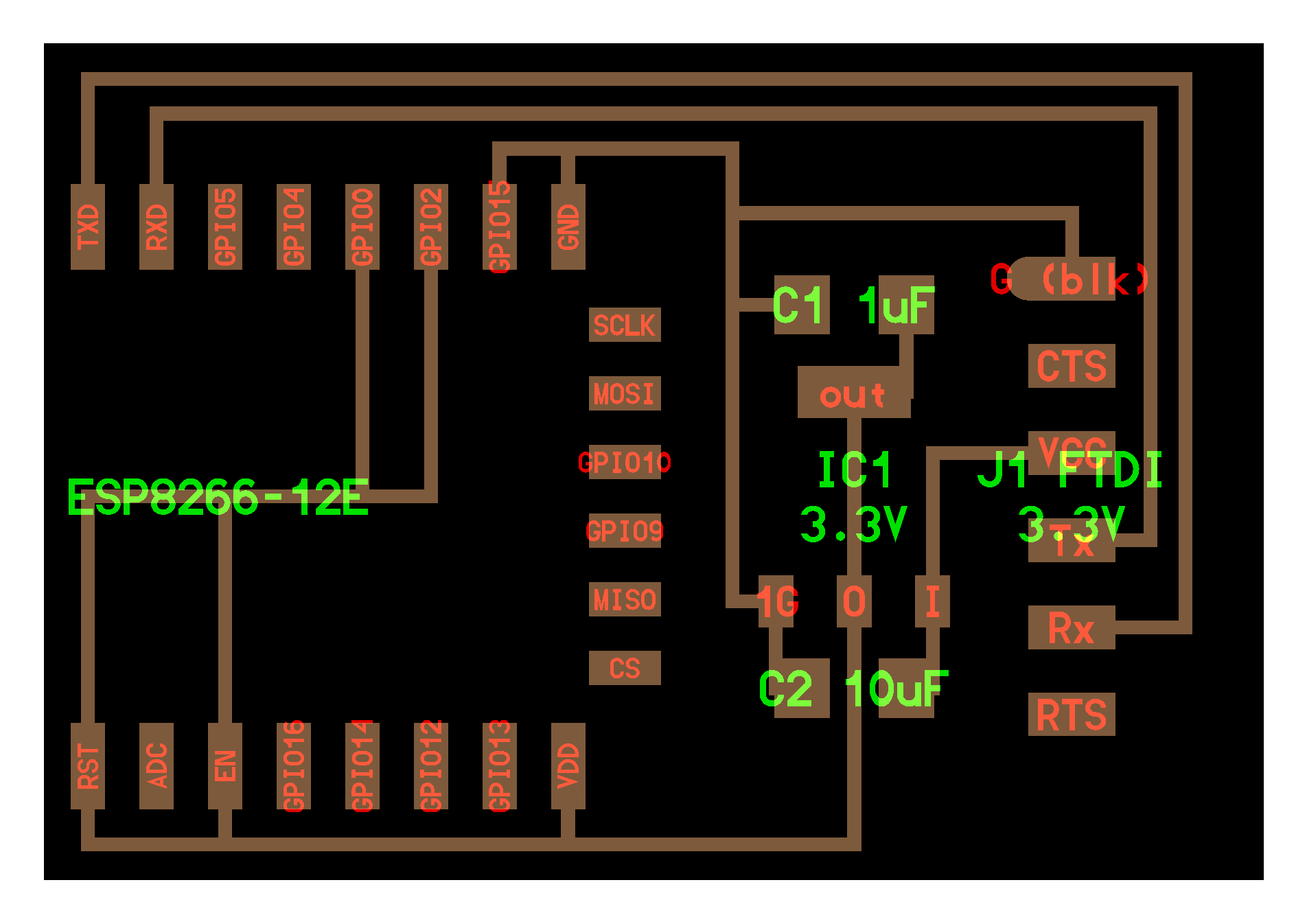
Adding battery to the schematic
My last question is how to add the battery to the schematic. Do I just add a JST connector and run traces from VCC to GND?
And what about the FTDI? It also supplies power. How do I combine these two? (Obviously you must unplug the FTDI when using the battery and vice versa. But how do I route this in my schematic?)
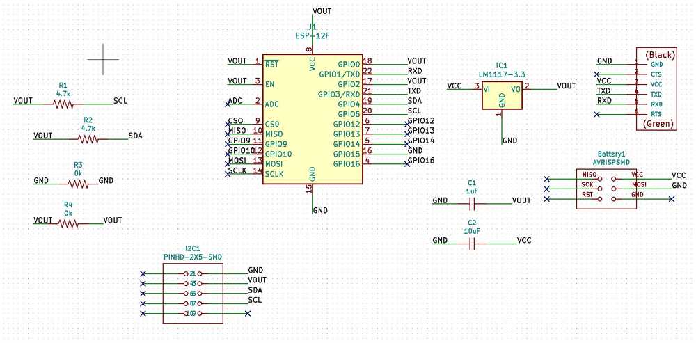
In my schematic I labeled VCC and VOUT. VCC is the 5V, VOUT is the current that has flown through the voltage regulator and is thus 3.3V. The battery must also start at VCC and must be routed through the voltage regulator.
I also now see that the I2C pinheaders have VCC. That seems correct as they must receive 5V. So they must come before the voltage regulator.
(June 10, 2020. This is in fact incorrect. I2C can run on different voltages.)
I check with Henk to see about routing the battery. He confirms that you must give the battery routing the same VCC start point and the same GND endpoint as the FTDI. We discuss whether it should be placed before or after the FTDI. Since you will not use the FTDI when using the battery it need not be included in the current flow. So I will place the battery GND and VCC just after the FTDI.
I also learn from Henk we don’t have JST connectors in stock. He says you can use just any two pins. I’ll add a 6-pin header. Yes overkill, but I hope to be able to use the rainbow colored mribbon cables, rather then two wires with a female connector. They have more grip and I don’t want my current influx to be shaky.
Conclusion
So I think I can use 4AA batteries to power this and my other modules. I’d prefer the NiHM as you can recharge them. But they are less powerfull than Alkaline so I may need to use those. But this I can test.
I’ll use a 6-pin header for the battery.
Battery will run in series.
(On a later date I learned new things about batteries from Henk. For the ESP32 board I will implement what I learned. The description of that part on batteries is under the segment about designing the ESP32 board.)
Component list
| component | quantity |
|---|---|
| ESP-12F | 1 |
| 6-pin FTDI header | 1 |
| 10-pin 2x5 header male | 1 |
| 6 pin header 2x3 male | 1 |
| Voltage regulator 3.3V | 1 |
| capacitor polarized 1uF | 1 |
| capacitor polarized 10uF | 1 |
| 10-header pin (I2C): PINHD-2X5-SMD | 1 |
| 4.7k ohm resistors | 2 |
| 0k ohm resistors | 2 |
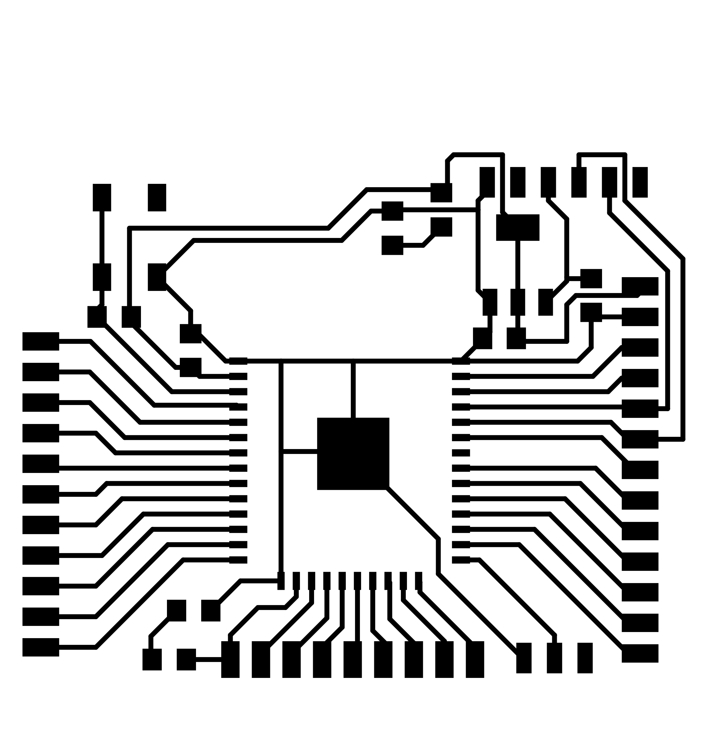
Kicad Eschema and PCB
My final Eschema:
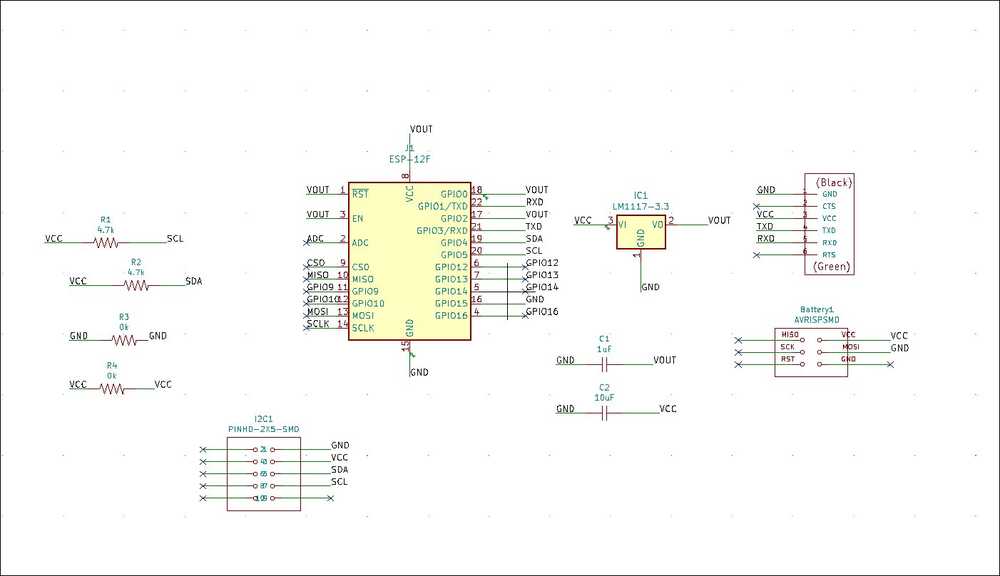
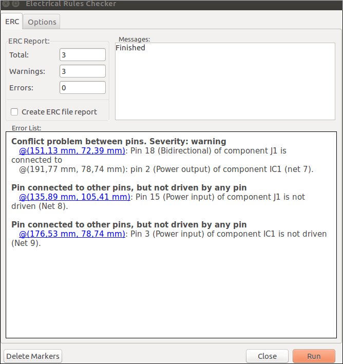
I did get this error in the ERC. But this setup is based on Neil’s board and I have checked many of the boards on the Fab archive and it is a much used wiring.
Mistake
After I finalized the board I went to bed. Sleep brought me insight. When I woke up I realized I made a mistake. I have 3.3V and 5V running in the same circuit. That probably is not a good idea. I’ll reroute so that all components are behind the voltage regulator.
This will give me a problem down the line. For my final project I want different modules talking over I2C. But I may have 5V and 3.3V modules. There are two solutions. Either I run all my modules over 3.3V. I’ll have to see if all can run on 3.3V. Or have an I2C bus with different volatges. This is possible. I read that when researching I2C. But I’ll have to figure out how. I quickly searched and saw the problem discussed on this forum for instance. But that is for later. First reroute the board.
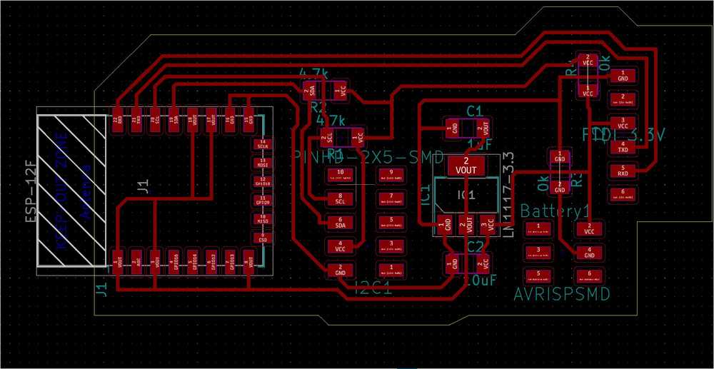
So, as you can see in the PCB outline above, 5V comes in from the power source. It goes through the voltage regulator to be brought down to 3.3V (VOUT) because the ESP pops at 5V. But the I2C component is wired to 5V (VCC). So now I have to rerout so the I2C components are also hooked to VOUT instead of VCC.
Second version
Rerouted schematic.
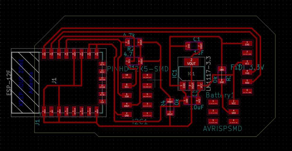
Rerouted PCB.
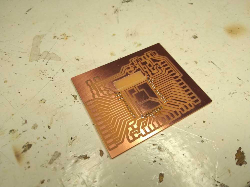
Milling the board: changes and mistakes
New milling setting. Henk milled the board. Thus far we have always used .004 inch cut depth. Now he has changed it to .003 inch (0.0762mm). He told us not once, but twice to put that in our documentation. So here it is! ;).
Henk showed me that Mods did not like my cutout. It showed extra lines. Later he found out what was wrong. I had drawn a cutout line of 0.1mm. But the drill is 0.8 mm. My cutout could be done anyway by inverting the cutout.jpg so the cutout was on both sides of the line. But that was how those extra lines came into existence. So for the future make sure when drawing a cutout in in KiCad to set it to 0.8 mm.
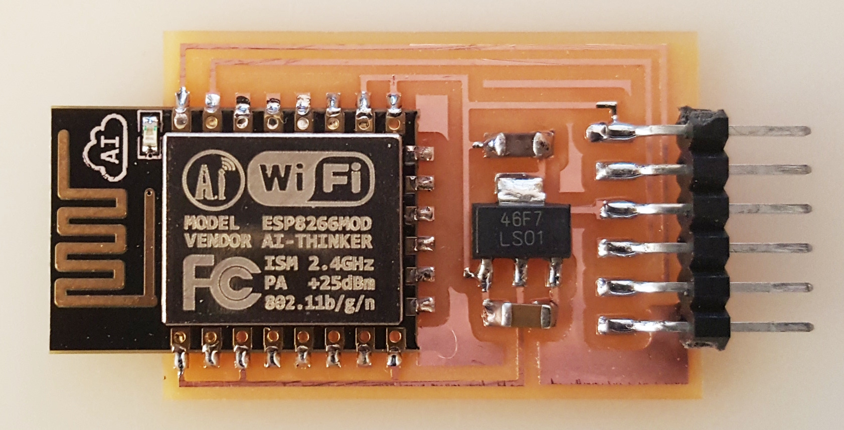
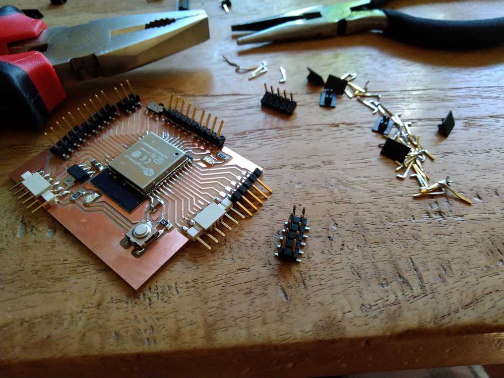
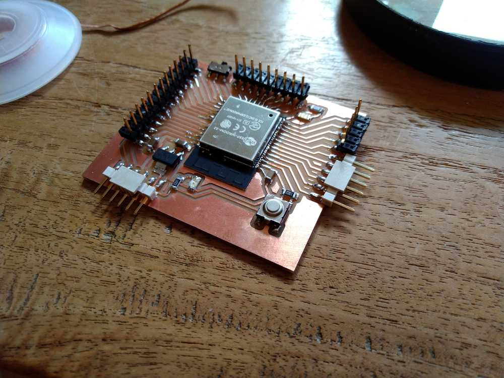
Soldering
My final board after milling and soldering.
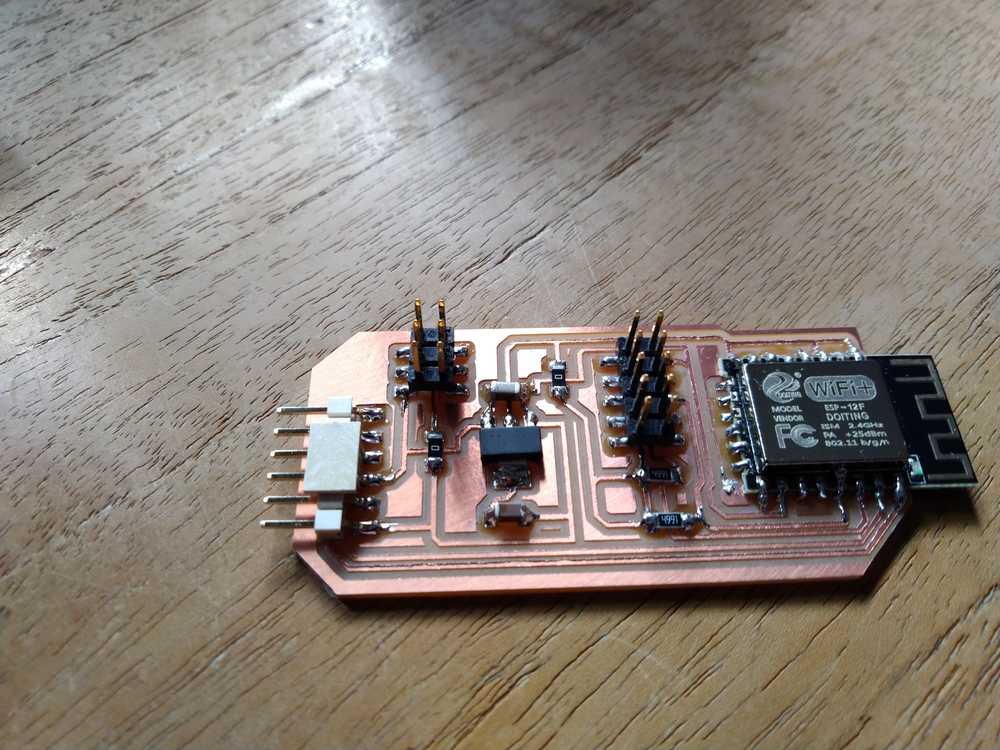
Programming
Board is dead on arrival. Does not even blink. Spend the evening trying to figure out. Did not document while working as I usually do, so here is a short summary of possible reasons:
- GPIO0 pin must be pulled to LOW when flashing firmware. In my schematic it is pulled HIGH. You need a button to pull LOW. Often described on the fora you need to push the button while Arduino IDE is uploading and then let go of button as it states: ‘connecting’.
This is one possibility. I considered Frankensteining a button to my board (scratch trace away solder wires connected to button instead). But exactly the trace that pulls the GPIO0 HIGH runs under the ESP module. No way to reach it without desoldering. - Some people flash the board with the custom firmware of Esspressif. But that is only provided for Windows.
- The battery addition I made to Neil’s board messed things up.
- The I2C addition I made messed things up.
- 3.3V I am using the FTDI plugged to computer to power the board. People warn against that. I am stubborn, that is why I added that voltage regulator right! That should work! But maybe it doesn’t.
- Settings in Arduino IDE are wrong.
- One million other options.
Oh yes, one funny thing. My class mate Harm also made the ESP board. He documents two weeks of trying and failing. Then he says: ‘I have found the solution! Follow this link!’. So I eagerly click the link only to land land on a 404. Today I asked Harm for the correct link and here it is: http://fabacademy.org/2020/labs/waag/students/harm-vanvugt/archive/2020/01/01/ESP12Fboard.html.
Breadboard: waking up this morning I returned to the idea I dimissed at the beginning of the week: the breadboard. I’d really just like to try out configuration before going through the whole KiCad thing. But I run into the same problem: don’t have a 3.3V input. I am considering buying power input for bread boards.
Another idea: rebuild a NodeMCU. Node is open source and schematics are available. Here is a datasheet for NodeMCU hardware overview and schematic. The schematics are Altium and can be viewed here.
Local and regional review - many many great tips & insights
During both local and regional review many important insights were shared. More than usual many of us worked on the same thing: I2C and ESP modules. And so we could learn from each other’s insights.
- ESP board needs buttons: Harm found out through trial and error that there is no way around it. So I’ll have to redesign my board to include to buttons. There is one but though. Neil made a board without buttons, many students made it and got it to work. They just never explain how they got it to work. It is something with AT commands. But never mind that. I’ll remake the board with buttons. Harm’s page.
- I2C slave bug in ESP. Florent found out that there is a bug for Arduino ESP and NodeMCU. It prevents the ESP module from acting as a slave in a I2C setup. It can only be a master. Here is Florent’s page for this week with the bug described. I wanted to use I2C for my final project with the ESP as slave. So thanks to Florent for figuring this out. It will save a lot of time.
- Henk ran into a problem with I2C in his time. He added pullup resistors. But then found out that many I2C devices already have pullup resistors build in. So with double pullups, I2C would not work. So this is also something to take into consideration.
- Nathan added a battery to his schematic so I will check if my solution looks like his.
Here is a collection of links I gathered yesterday evening. They are for my own reference.
Here is a 2016 student who also had issues programming.
Fab tutorial on ESP8266
Python and 8266
Flash boot mode
Flashing from firmware
My error described: not connecting: ‘Hold down boot flash buttton. Press upload. When you see ‘connecting’ release button.’
Yeah so the GPIO0 pin needs to be pulled low to upload a sketch. But I did not add a button to my schematic…
Neil’s python script to check the connection.
Explains a lot but for esp01
Netconcept: great info: On Linux:
At first you should have installed 2 components :
minterm.py
python serial
Connect the Electronic you constructed with the FTDI cable with your computer. Verify that your Linux recognize your serial device with the : lsusb command. Check the /dev subdirectory. Search for the ttyUSB devices: ls -la ttyUSB*. You will receive something like : ttyUSB0 or ttyUSB1. Use the info you get with the command: sudo miniterm.py /dev/ttyUSB1 112500
On using a LCD with the ESP.
Also link to Neil’s design with two buttons.
Wifi library.
ESP12F datasheet
Pivoting to ESP32
I am coming back to this assignment June 10, 2020. Since then I considered pivoting from the ESP8266 to the ESP32. For one, the ESP32 does not seem to have the I2C bug (Described above: the ESP8266 can only be a master in the I2C scheme but not a slave). This is quite relevant for my purposes as I want to have the ESP board in a chain of boards with another board being the I2C master.
Here is a link to official documentation on the ESP32 and I2C.
Here is a link to the official development environment for the ESP32.
The ESP32 can also do mesh networking: ESP32 mesh.
It is a bit of a shame to let o of the ESP8266. I am still curious if I can get this board to work if I applied the things I learned since first discovering it does not work. But I will do this in another spiral.
My class mate Hyejin pointed out the Barduino. It is a development board for the ESP32 developed by the Barcelona FabLab. What I like about it is that it breaks out all the pins. I can use this for prototyping and then make my own board. I can then take away all the components and/or pins I do not need.
There multiple Barduino versions. I did not look into the Barduino 1.0. But I compared the 2.0, 2.1 and 2.2. I want to go with the 2.0 because it has an external FTDI. The other versions have an onboard FTDI module. But that means an extra component. And I still want to make as simple a board as possible for the Post-collapse Network. Plus, a separate FTDI board can be used for multiple boards. Whereas an on-board FTDI module can only be used for that specific board. So it is less modular.
The KiCad design that is provided on the Barduino site does not work entirely correctly. The 2.1 and 2.2 KiCad files work but the 2.0 give some errors.
But that does not really matter as I can easily redraw it.
Here is the Eagle files of the Barduino loaded into the altrium.com viewer.
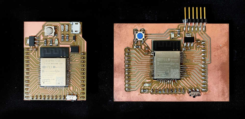
Here is a comparison picture between the Barduino 2.0 and 2.2.Source. On the left the 2.2 with an on-board FTDI module. On the right the 2.0 with its distinctive FTDI header.
Here is the components file for the Barduino 2.0
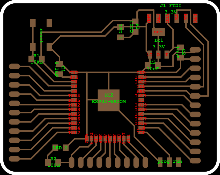
This is the original traces file from the Barduino site. Hyejin ran into some trouble with that design during soldering. She made some changes to the design and she was kind enough to share it with me.

This is the original cut-out for the antenna. You can have the antenna above the copper board because it will interfere with signals. Neil usuallu let’s the antenna hang outside the board. Like I did with my ESP8266 design. The Barduino folks have chosen to place the ESP32 in the middle of the board and mill away the copper underneath the antenna.
During milling I used the 0.8mm drill to do this to spare the 0.4 drill bit. I put the offset number to 0 which is the setting to drill all the copper away. (See week04)

The original Barduino has through holes to fasten the pins. I did not use this. Instead I to 2x5 pin headers and removed 1 row of pins. Leaving me with non-through-hole SMD 1x5 header pins that I can solder to the board.

The original outline of the Barduino.
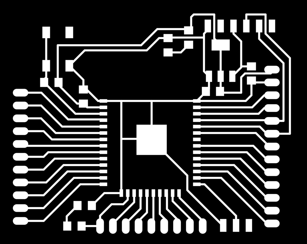
This is Hyejin’s design. The difference is that she made the pads for soldering on the pads for the ESP32 bigger. Also she replaced the holes for the pins with SMD pads. This way you do not need through-hole pins but instead can solder SMD pins on the pads.
The antenna and the outline file are the same in Hyejin’s redesign. The through-hole file is no longer necessary obviously.
Milling
The 0.4mm drill broke during milling and I had to start over. But then it came out pretty nice.
Soldering
BOM
1 x WIFI MODULE 32MBITS SPI FLASH
1 x RES 10.0K OHM 1/4W 1% 1206 SMD
1x SWITCH TACT SMD W-GND 160GF
2 x CAP CER 10UF 35V Y5V 1206
1 x IC REG LDO 3.3V 1A SOT223-3
2 x LED RED CLEAR 1206 SMD
2 x RES 100 OHM 1/4W 1% 1206 SMD
1 x SWITCH SLIDE SPDT 12V 100MA GW-
1 x CAP CERAMIC .1UF 250V X7R 1206
6 x 1x5 row SMD pin header.
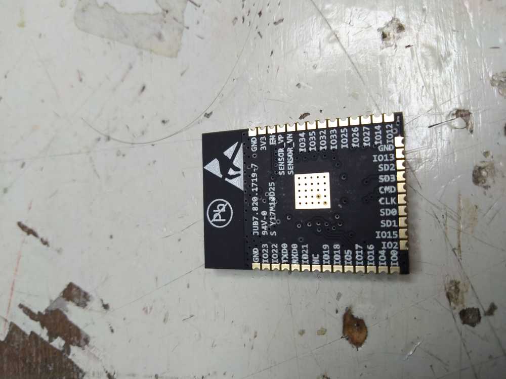
Before soldering it onto the board I took a picture of the back of the ESP32. It has teh pin-out information on it.
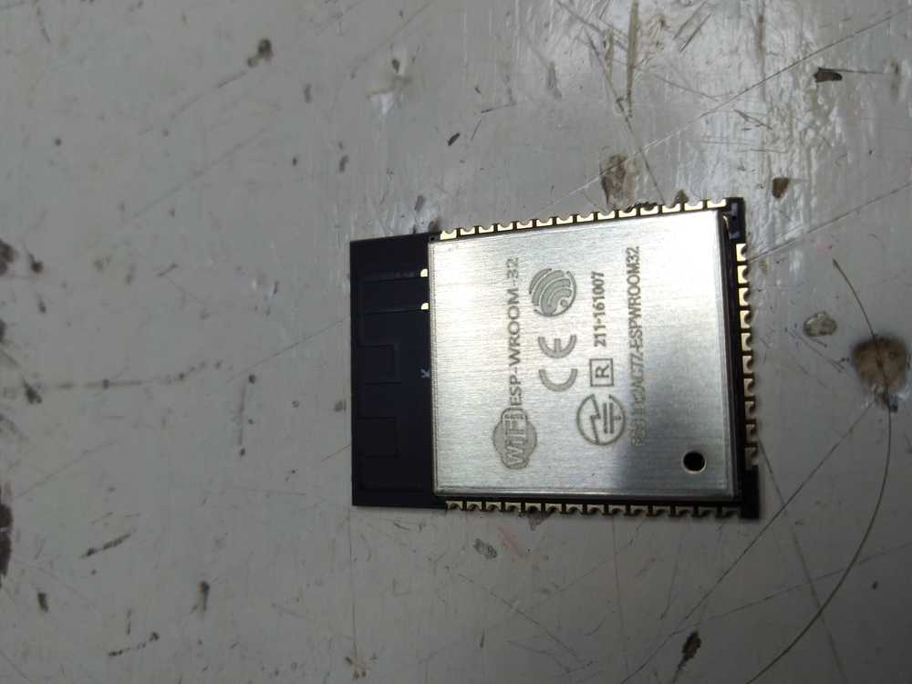
And for good measure the front:
Soldering went pretty well. The only thing I ran into is the 100Ohm resistor. I took the box that was labeled 100Ohm resistor but the resistors inside had the number 1000 written on them. I asked Harm and he pointed me to this site that explains the coding on SMD resistors. The code is 1000 because the last zero indicates how much zero’s you must add. So 10kOhm is 1002. 100Ohm is 100 plus zero zero’s.
As described above, instead of using through-holes, I made SMD pads. That meant turning 2x5 SMD pin-headers into 1x5 SMD pinheaders using plyers.
I wasn’t yet done soldering when the lab closed. I thought I only needed to add the headers. But than I saw that I had forgotten a capacitor next to the voltage regulator. I canibalized my ESP8266 board, desoldered the 10uF capacitor and added it to the ESP32.
Finished board.
Voltage regulator
What I noticed is that in the Barduino the two capacitors around the voltage regulator are both 10uF. Whereas in my ESP8266 board the two capacitors have different values. I looked up voltage regulators. Appearantly the capacitor that comes after the voltage regulator is less important. The first one makes sure a clean signal goes into the regulator. In that it does not fluctuate. The one after the voltage regulator also cleans up the signal. If you have a simple design with LEDs for instance, you need not clean up the signal because LEDs can handle a little noise. But if you do more delicate stuff like the ESP32 it too wants a clean signal, hence the second capacitor. It did not say anything about the values of the capacitors. In the linked example, the two capacitors also have different values.
StackExchange further explains that you need to check the datasheet to see what capacitor value you need. It also said that you can go up in capacitor value if you want.
Here is the datasheet for the voltage regulator. And it says indeed to use 2x 10uF.
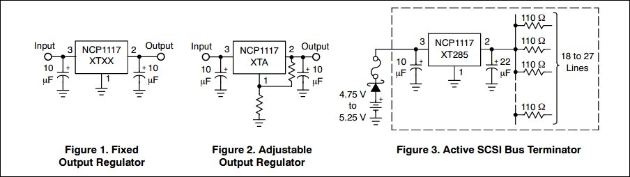
image taken from the voltage regulator datasheet
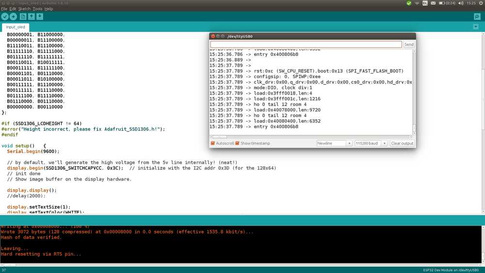
Programming the ESP32
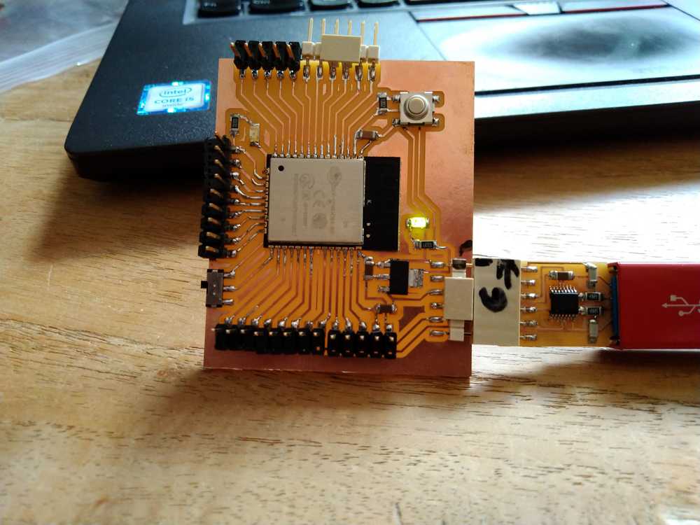
First plug-in into the computer’s USB port. LED is HIGH. Yay! Board is not dead on arrival!
Important settings are: Board (ESP32DevModule) & Port. The other settings I left to default. The Programmer setting is irrelevant for the ESP32, any setting will do.
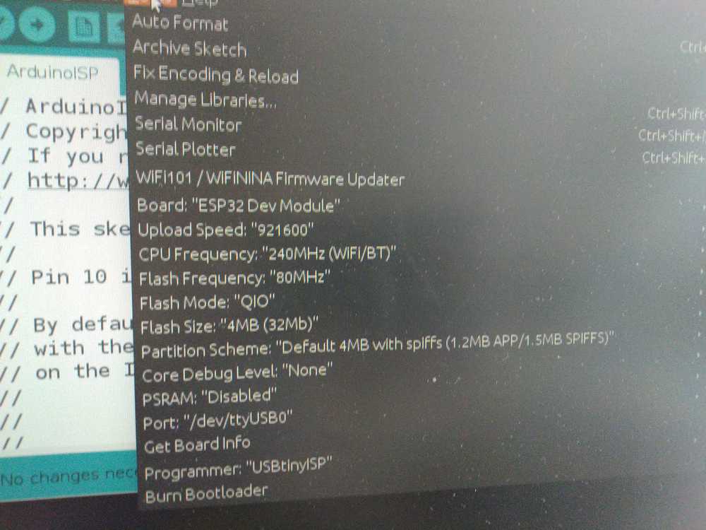
Settings on Arduino. The board is seen by Arduino
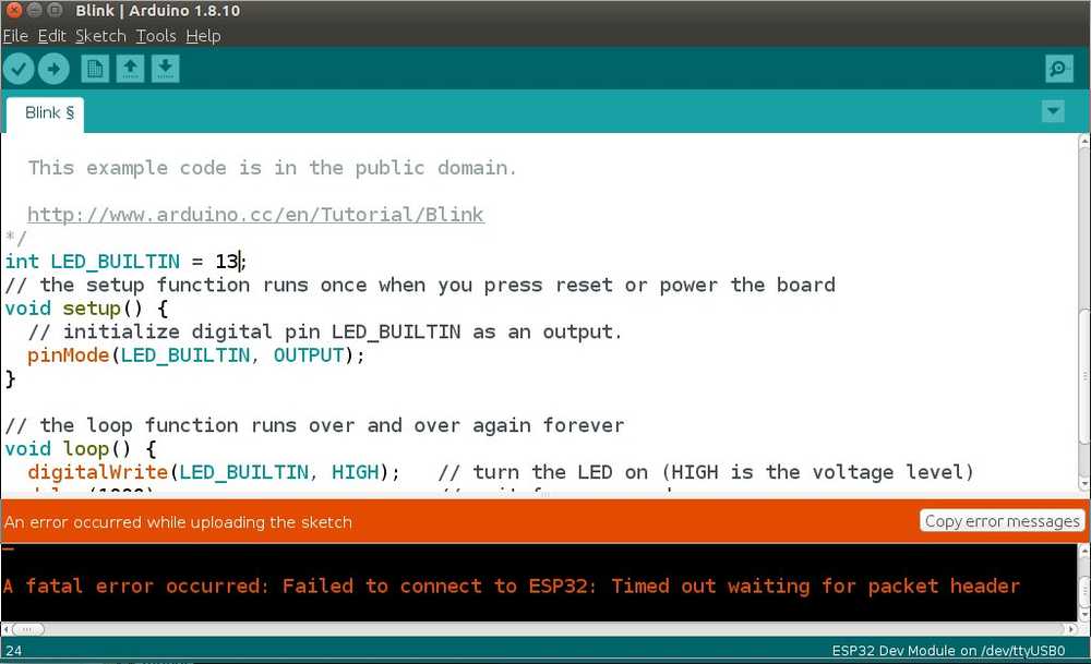
But it does not work. Fatal error time out.
Looking up if I need to do something with the switch and push button.
Found people had the same thing on Github.
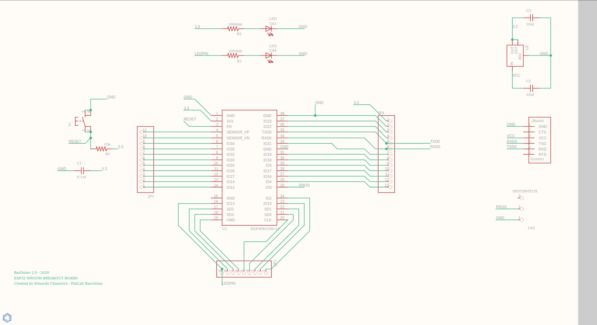
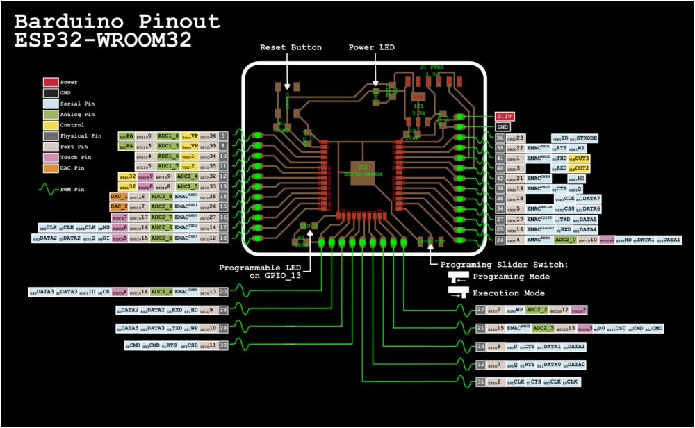
What you need to do is place the switch in programming mode. Here is the Barduino schematic provided on the Barduino website. At the bottom right you see the switch. It has a programming mode and an execute mode.
Then as Arduino IDE is uploading, the panel states connecting.... As this happens you press the RST button. Hold down for about a second. Don’t wait for the Arduino to start programming. Then you’ll get a fatal error. Press down and let go up again during the time connecting is displayed. After the dots appear I wait till the dots turn into a line, then I press the button.
Then when the code is uploaded, you need to place the switch in execution mode. Then press the RST button again. And it should work.
Note that sometimes you don’t have to press the RST button. For the example code TouchRead from the ESP32 library. The RST button killed the upload whereas leaving it alone led to a successfull upload.
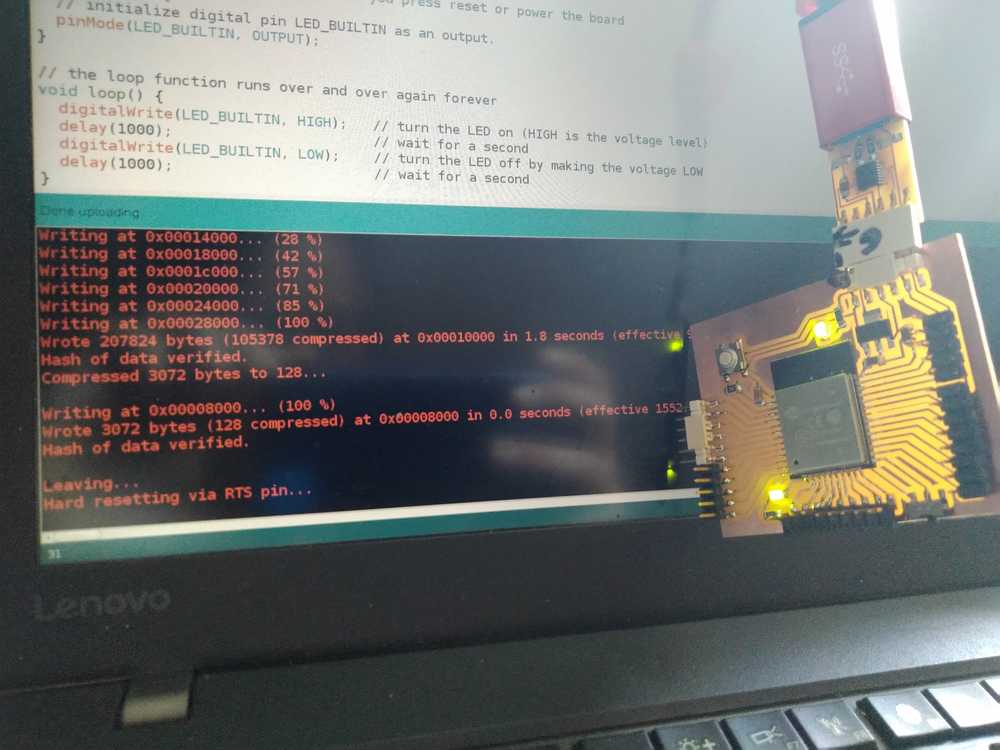
Succesfully uploaded Blink code.
Video working Blink.
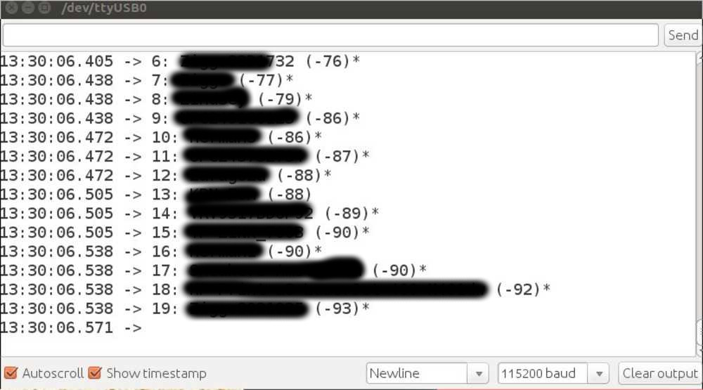
I then upload a WiFi scan that is provided under the Arduino examples. And it works. Output on the serial monitor. (Wifi names obscured for privacy.)
Mesh networking on the ESP32
I tried to upload the same painlessMesh Library examples on the ESP32 as I did on the NodeMCU and the Feather. But I get the error Error compiling for board ESP32 Dev Module. I find that for painlessMesh to work on the ESP32 I need an extra library AsyncTCP
It was a bit confusing because a similar library is necessary for the ESP8266 and they both have the same name. So it seemed as if I already had installed the library. But when I compared the README files the one said it was for the ESP8266 and the other for the ESP32. I want to keep the ESP8266 library as well. So I renamed the ESP32 library to AsyncTCP-master2. I wondered if that would work. Perhaps naming is relevant in the Arduino scheme. But when I verified the sketch it worked.
Note: when the ESP32 is online and you power up another node, the new node will not show anything on the serial monitor. You need to reset the new node. In most cases it will still not see the ESP32. Reset the ESP32 too and then the two nodes will see each other. The other way around works better. When the ESP32 is already running and a new node is powered up, after some delay the ESP32 will post a message on the serial monitor that a new node is detected. So no resetting needed.
It works and the ESP32 sees the NodeMCU.
This is the code used. It is the Basic example from the painlessMesh library.
//************************************************************
// this is a simple example that uses the painlessMesh library
//
// 1. sends a silly message to every node on the mesh at a random time between 1 and 5 seconds
// 2. prints anything it receives to Serial.print
//
//
//************************************************************
#include "painlessMesh.h"

#define   MESH_PREFIX     "whateverYouLike"
#define   MESH_PASSWORD   "somethingSneaky"
#define   MESH_PORT       5555

Scheduler userScheduler; // to control your personal task
painlessMesh  mesh;

// User stub
void sendMessage() ; // Prototype so PlatformIO doesn't complain

Task taskSendMessage( TASK_SECOND * 1 , TASK_FOREVER, &sendMessage );

void sendMessage() {
  String msg = "Hello from node ";
  msg += mesh.getNodeId();
  mesh.sendBroadcast( msg );
  taskSendMessage.setInterval( random( TASK_SECOND * 1, TASK_SECOND * 5 ));
}

// Needed for painless library
void receivedCallback( uint32_t from, String &msg ) {
  Serial.printf("startHere: Received from %u msg=%s\n", from, msg.c_str());
}

void newConnectionCallback(uint32_t nodeId) {
    Serial.printf("--> startHere: New Connection, nodeId = %u\n", nodeId);
}

void changedConnectionCallback() {
  Serial.printf("Changed connections\n");
}

void nodeTimeAdjustedCallback(int32_t offset) {
    Serial.printf("Adjusted time %u. Offset = %d\n", mesh.getNodeTime(),offset);
}

void setup() {
  Serial.begin(115200);

//mesh.setDebugMsgTypes( ERROR | MESH_STATUS | CONNECTION | SYNC | COMMUNICATION | GENERAL | MSG_TYPES | REMOTE ); // all types on
  mesh.setDebugMsgTypes( ERROR | STARTUP );  // set before init() so that you can see startup messages

  mesh.init( MESH_PREFIX, MESH_PASSWORD, &userScheduler, MESH_PORT );
  mesh.onReceive(&receivedCallback);
  mesh.onNewConnection(&newConnectionCallback);
  mesh.onChangedConnections(&changedConnectionCallback);
  mesh.onNodeTimeAdjusted(&nodeTimeAdjustedCallback);

  userScheduler.addTask( taskSendMessage );
  taskSendMessage.enable();
}

void loop() {
  // it will run the user scheduler as well
  mesh.update();
}
Next I tried another example code from the painlessMesh library called StartHere:
//************************************************************
// this is a simple example that uses the easyMesh library
//
// 1. blinks led once for every node on the mesh
// 2. blink cycle repeats every BLINK_PERIOD
// 3. sends a silly message to every node on the mesh at a random time between 1 and 5 seconds
// 4. prints anything it receives to Serial.print
//
//
//************************************************************
#include <painlessMesh.h>

// some gpio pin that is connected to an LED...
// on my rig, this is 5, change to the right number of your LED.
#define   LED             2       // GPIO number of connected LED, ON ESP-12 IS GPIO2

#define   BLINK_PERIOD    3000 // milliseconds until cycle repeat
#define   BLINK_DURATION  100  // milliseconds LED is on for

#define   MESH_SSID       "whateverYouLike"
#define   MESH_PASSWORD   "somethingSneaky"
#define   MESH_PORT       5555

// Prototypes
void sendMessage();
void receivedCallback(uint32_t from, String & msg);
void newConnectionCallback(uint32_t nodeId);
void changedConnectionCallback();
void nodeTimeAdjustedCallback(int32_t offset);
void delayReceivedCallback(uint32_t from, int32_t delay);

Scheduler     userScheduler; // to control your personal task
painlessMesh  mesh;

bool calc_delay = false;
SimpleList<uint32_t> nodes;

void sendMessage() ; // Prototype
Task taskSendMessage( TASK_SECOND * 1, TASK_FOREVER, &sendMessage ); // start with a one second interval

// Task to blink the number of nodes
Task blinkNoNodes;
bool onFlag = false;

void setup() {
  Serial.begin(115200);

  pinMode(LED, OUTPUT);

  mesh.setDebugMsgTypes(ERROR | DEBUG);  // set before init() so that you can see error messages

  mesh.init(MESH_SSID, MESH_PASSWORD, &userScheduler, MESH_PORT);
  mesh.onReceive(&receivedCallback);
  mesh.onNewConnection(&newConnectionCallback);
  mesh.onChangedConnections(&changedConnectionCallback);
  mesh.onNodeTimeAdjusted(&nodeTimeAdjustedCallback);
  mesh.onNodeDelayReceived(&delayReceivedCallback);

  userScheduler.addTask( taskSendMessage );
  taskSendMessage.enable();

  blinkNoNodes.set(BLINK_PERIOD, (mesh.getNodeList().size() + 1) * 2, []() {
      // If on, switch off, else switch on
      if (onFlag)
        onFlag = false;
      else
        onFlag = true;
      blinkNoNodes.delay(BLINK_DURATION);

      if (blinkNoNodes.isLastIteration()) {
        // Finished blinking. Reset task for next run
        // blink number of nodes (including this node) times
        blinkNoNodes.setIterations((mesh.getNodeList().size() + 1) * 2);
        // Calculate delay based on current mesh time and BLINK_PERIOD
        // This results in blinks between nodes being synced
        blinkNoNodes.enableDelayed(BLINK_PERIOD -
            (mesh.getNodeTime() % (BLINK_PERIOD*1000))/1000);
      }
  });
  userScheduler.addTask(blinkNoNodes);
  blinkNoNodes.enable();

  randomSeed(analogRead(A0));
}

void loop() {
  mesh.update();
  digitalWrite(LED, !onFlag);
}

void sendMessage() {
  String msg = "Hello from node ";
  msg += mesh.getNodeId();
  msg += " myFreeMemory: " + String(ESP.getFreeHeap());
  mesh.sendBroadcast(msg);

  if (calc_delay) {
    SimpleList<uint32_t>::iterator node = nodes.begin();
    while (node != nodes.end()) {
      mesh.startDelayMeas(*node);
      node++;
    }
    calc_delay = false;
  }

  Serial.printf("Sending message: %s\n", msg.c_str());

  taskSendMessage.setInterval( random(TASK_SECOND * 1, TASK_SECOND * 5));  // between 1 and 5 seconds
}


void receivedCallback(uint32_t from, String & msg) {
  Serial.printf("startHere: Received from %u msg=%s\n", from, msg.c_str());
}

void newConnectionCallback(uint32_t nodeId) {
  // Reset blink task
  onFlag = false;
  blinkNoNodes.setIterations((mesh.getNodeList().size() + 1) * 2);
  blinkNoNodes.enableDelayed(BLINK_PERIOD - (mesh.getNodeTime() % (BLINK_PERIOD*1000))/1000);

  Serial.printf("--> startHere: New Connection, nodeId = %u\n", nodeId);
  Serial.printf("--> startHere: New Connection, %s\n", mesh.subConnectionJson(true).c_str());
}

void changedConnectionCallback() {
  Serial.printf("Changed connections\n");
  // Reset blink task
  onFlag = false;
  blinkNoNodes.setIterations((mesh.getNodeList().size() + 1) * 2);
  blinkNoNodes.enableDelayed(BLINK_PERIOD - (mesh.getNodeTime() % (BLINK_PERIOD*1000))/1000);

  nodes = mesh.getNodeList();

  Serial.printf("Num nodes: %d\n", nodes.size());
  Serial.printf("Connection list:");

  SimpleList<uint32_t>::iterator node = nodes.begin();
  while (node != nodes.end()) {
    Serial.printf(" %u", *node);
    node++;
  }
  Serial.println();
  calc_delay = true;
}

void nodeTimeAdjustedCallback(int32_t offset) {
  Serial.printf("Adjusted time %u. Offset = %d\n", mesh.getNodeTime(), offset);
}

void delayReceivedCallback(uint32_t from, int32_t delay) {
  Serial.printf("Delay to node %u is %d us\n", from, delay);
}
This code works on the NodeMCU but throws an error on the ESP32.
I looked up the first line of the error code rst:0xc (SW_CPU_RESET), boot:0x13 (SPI_FAST_FLASH_BOOT). On github more people report this error message. It indicates the ESP is rebooting over and over.
But other code does work, so unlike the people on the Github page, I’m not dealing with a system-wide error.
So I searched more specifically on errors relating to ESP32 and the StartHere code. On gitlab someone had this problem and solved it by replacing this line:
mesh.setDebugMsgTypes(ERROR | DEBUG | CONNECTION); // set before init() so that you can see startup messages
for this line:
mesh.setDebugMsgTypes( ERROR | MESH_STATUS | CONNECTION | SYNC | COMMUNICATION | GENERAL | MSG_TYPES | REMOTE ); // all types on
But when I check I see that my example code does not have the CONNECTION after DEBUG.
So I change my code by adding ‘connection’ and then the code works.
BlackEdder, core developer of painlessMesh, responded with the reason why the line made the ESP crash: ‘I have been trying to debug this, and as far as I can tell it is a race condition (ESP32 is multicore). Adding the debugLogging probably slows the code down enough such that the race does not occur. Race conditions are quite hard to debug and fix, but I am working on it ;)’
What is strange is that the developer fixed this bug a year ago. I checked if I have the most up-to-date library. But the library has not version mentioned in the README. I decide to leave it for now and keep this in mind if I run into other errors.
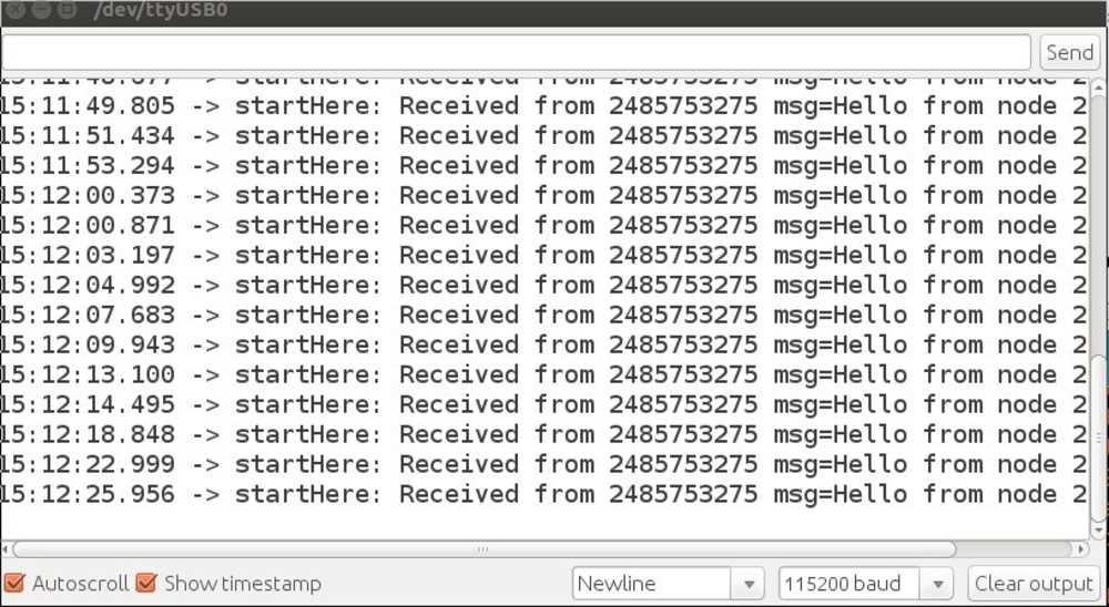
The code results in different behaviors in the ESP8266 and the ESP32.
ESP8266 only outputs messages sent and received.
ESP32 outputs network status as well.
Sending sensor output to the mesh network
Next up I am going to try to send sensor data over the network. The ESP32 has 10 TOUCH pins. When you touch this pin it sends a value to the serial monitor. I want to use 4 TOUCH pins to send morse code over the mesh network.
So what I need to do is for the ESP32 to read the touch pins and if there is input, to broadcast this over the network. I am using this tutorial as an example. This person is reading data from a humidity sensor and sending that over the network. I am hoping to adjust this to read the touch sensors instead and send it over the network.
I have all the components for the setup of the tutorial: humidity sensor, buttons and LEDs.
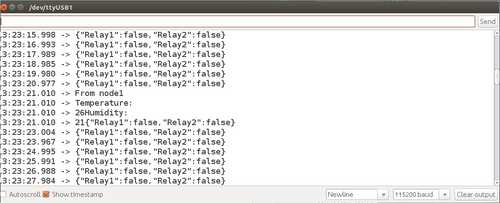
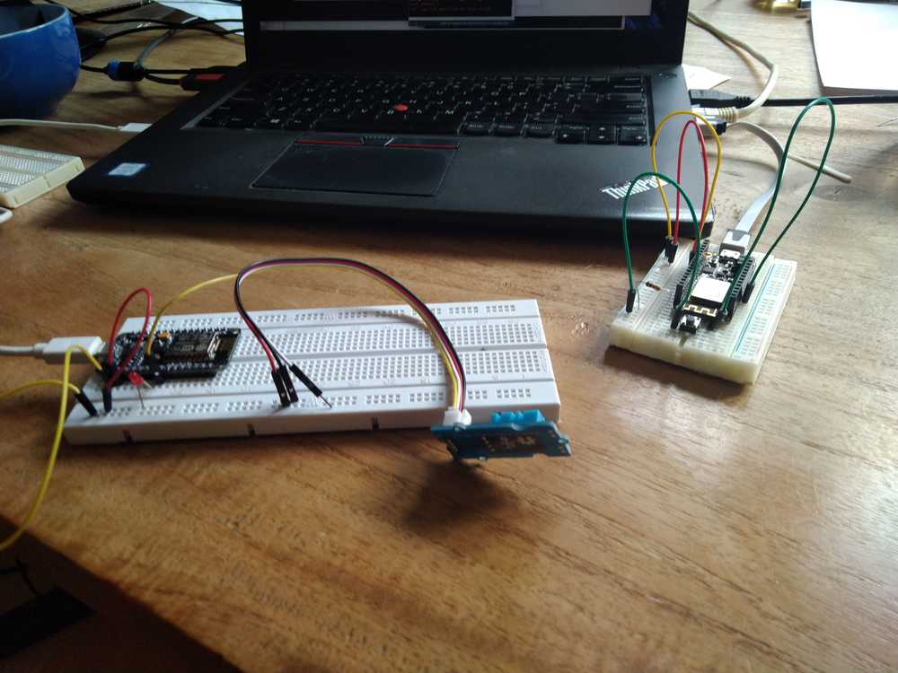 I try the tutorial’s code out on the Feather and the NodeMCU. The NodeMCU is node 2 and the Feather is Node 1. That works. (The relay on Node one is a button that controls the LED of node 2. I only have one button instead of two. Therefore Relay1 will always be false. But that is not important for what I’m testing. The point here is to have input from the sensor send to the other node.)
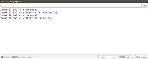
Output from Node 1 is:
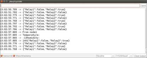
And node 2:
Code node 1: this is the code from the tutorial.
// Code for Node1:
#include "painlessMesh.h"
// WiFi Credentials
#define   MESH_PREFIX     "whateverYouLike"
#define   MESH_PASSWORD   "somethingSneaky"
#define   MESH_PORT       5555
bool button1_status = 0;
bool button2_status = 0;
//Pin Declaration
#define Button1 13
#define Button2 14
Scheduler userScheduler;
painlessMesh  mesh;
void sendMessage() ;
Task taskSendMessage( TASK_SECOND * 1 , TASK_FOREVER, &sendMessage );
void sendMessage()
{
// Reading Status of Pushbutton
  if (digitalRead(Button1) == HIGH)
    button1_status = !button1_status;
  if (digitalRead(Button2) == HIGH)
    button2_status = !button2_status;
// Serializing in JSON Format
  DynamicJsonDocument doc(1024);
  doc["Relay1"] = button1_status;
  doc["Relay2"] = button2_status;
  String msg ;
  serializeJson(doc, msg);
    mesh.sendBroadcast( msg );
  Serial.println(msg);
  taskSendMessage.setInterval((TASK_SECOND * 1));
}
void receivedCallback( uint32_t from, String &msg ) {
  String json;
  DynamicJsonDocument doc(1024);
  json = msg.c_str();
  DeserializationError error = deserializeJson(doc, json);
  if (error)
  {
    Serial.print("deserializeJson() failed: ");
    Serial.println(error.c_str());
  }
   String Temp = doc["TEMP"];
   String Hum = doc["HUM"];
  Serial.println("From node1");
   Serial.println("Temperature:");
   Serial.print(Temp);
    Serial.println("Humidity:");
   Serial.print(Hum);
}
void newConnectionCallback(uint32_t nodeId) {
  Serial.printf("--> startHere: New Connection, nodeId = %u\n", nodeId);
}
void changedConnectionCallback() {
  Serial.printf("Changed connections\n");
}
void nodeTimeAdjustedCallback(int32_t offset) {
  Serial.printf("Adjusted time %u. Offset = %d\n", mesh.getNodeTime(), offset);
}
void setup() {
  Serial.begin(115200);
  pinMode(Button1, INPUT);
  pinMode(Button2, INPUT);
  mesh.setDebugMsgTypes( ERROR | STARTUP );  // set before init() so that you can see startup messages
  mesh.init( MESH_PREFIX, MESH_PASSWORD, &userScheduler, MESH_PORT );
  mesh.onReceive(&receivedCallback);
  mesh.onNewConnection(&newConnectionCallback);
  mesh.onChangedConnections(&changedConnectionCallback);
  mesh.onNodeTimeAdjusted(&nodeTimeAdjustedCallback);
  userScheduler.addTask( taskSendMessage );
  taskSendMessage.enable();
}
void loop() {
  mesh.update();
}
Code node 2
// Code for Node2:
#include "painlessMesh.h"
#include <DHT.h>
// WiFi Credentials
#define   MESH_PREFIX     "whateverYouLike"
#define   MESH_PASSWORD   "somethingSneaky"
#define   MESH_PORT       5555
//Pin Declaration
#define Relay1 D6
#define DHTPIN D5
#define DHTTYPE DHT11     // DHT 11
DHT dht(DHTPIN, DHTTYPE);
//Variables
bool relay1_status = 0;
Scheduler userScheduler;
painlessMesh  mesh;
void sendMessage() ;
Task taskSendMessage( TASK_SECOND * 1 , TASK_FOREVER, &sendMessage );
void sendMessage()
{
  // Serializing in JSON Format
  DynamicJsonDocument doc(1024);
  float h = dht.readHumidity();
  float t = dht.readTemperature();
  doc["TEMP"] = t;
  doc["HUM"] = h;
  String msg ;
  serializeJson(doc, msg);
  mesh.sendBroadcast( msg );
  Serial.println("from node2");
  Serial.println(msg);
  taskSendMessage.setInterval((TASK_SECOND * 10));
}
// Needed for painless library
void receivedCallback( uint32_t from, String &msg ) {
  String json;
  DynamicJsonDocument doc(1024);
  json = msg.c_str();
  DeserializationError error = deserializeJson(doc, json);
  if (error)
  {
    Serial.print("deserializeJson() failed: ");
    Serial.println(error.c_str());
  }
  relay1_status = doc["Relay1"];
  digitalWrite(Relay1, relay1_status);
}
void newConnectionCallback(uint32_t nodeId) {
  Serial.printf("--> startHere: New Connection, nodeId = %u\n", nodeId);
}
void changedConnectionCallback() {
  Serial.printf("Changed connections\n");
}
void nodeTimeAdjustedCallback(int32_t offset) {
  Serial.printf("Adjusted time %u. Offset = %d\n", mesh.getNodeTime(), offset);
}
void setup() {
  Serial.begin(115200);
  pinMode(Relay1, OUTPUT);
  mesh.setDebugMsgTypes( ERROR | STARTUP );  // set before init() so that you can see startup messages
  mesh.init( MESH_PREFIX, MESH_PASSWORD, &userScheduler, MESH_PORT );
  mesh.onReceive(&receivedCallback);
  mesh.onNewConnection(&newConnectionCallback);
  mesh.onChangedConnections(&changedConnectionCallback);
  mesh.onNodeTimeAdjusted(&nodeTimeAdjustedCallback);
  userScheduler.addTask( taskSendMessage );
  taskSendMessage.enable();
}
void loop() {
  mesh.update();
}
I put the code on the ESP32 and that works too.
Touchpin data to mesh network
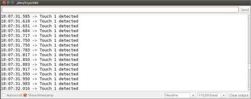
Next up is trying to get it to work with the touch pins. I will combine the code used above and code for manipulating the touch pins. This is touch pin example code is from the ESP32 library. It specifically addresses the touch pins. When you touch the pin a message is outputted on the serial monitor. The example is called ‘TouchInterupt’.
/*
This is un example howto use Touch Intrrerupts
The bigger the threshold, the more sensible is the touch
*/

int threshold = 40;
bool touch1detected = false;
bool touch2detected = false;

void gotTouch1(){
 touch1detected = true;
}

void gotTouch2(){
 touch2detected = true;
}

void setup() {
  Serial.begin(115200);
  delay(1000); // give me time to bring up serial monitor
  Serial.println("ESP32 Touch Interrupt Test");
  touchAttachInterrupt(T2, gotTouch1, threshold);
  touchAttachInterrupt(T3, gotTouch2, threshold);
}

void loop(){
  if(touch1detected){
    touch1detected = false;
    Serial.println("Touch 1 detected");
  }
  if(touch2detected){
    touch2detected = false;
    Serial.println("Touch 2 detected");
  }
}
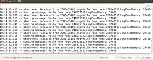
It takes me a while to figure out what the different parts of the code do. Examples and tutorials that helped are this one on touchpins and this one. And this tutorial on transmiting data using JSON. The code used in this tutorial is made available on Github. The code is in part very similar to the example code for sending humidity sensor data I used above. It also has extra features in that it outputs data to an OLED monitor. But when I upload that code onto my ESP32 I get the eternal-reboot crash.
Eventually I get it to work. This is the output on the serial monitor:
For my own reference: this stage is captured in code version 3: node1bar-v3.ino.
This is the code:
// Code for Node1:
#include "painlessMesh.h"


// WiFi Credentials
#define   MESH_PREFIX     "whateverYouLike"
#define   MESH_PASSWORD   "somethingSneaky"
#define   MESH_PORT       5555

// bool button1_status = 0;
// bool button2_status = 0;

int threshold = 40;
bool touch1detected = false;
bool touch2detected = false;

// Pin Declaration
// #define Button1 13
// #define Button2 14

#define touchPin1 13
#define touchPin2 14

Scheduler userScheduler;
painlessMesh  mesh;

void sendMessage() ;
Task taskSendMessage( TASK_SECOND * 1 , TASK_FOREVER, &sendMessage );
void sendMessage()
{
// Reading Status of Pushbutton
//  if (digitalRead(Button1) == HIGH)
//    button1_status = !button1_status;
//  if (digitalRead(Button2) == HIGH)
//    button2_status = !button2_status;

// Reading Status of touchPin
  if (digitalRead(touchPin1) == HIGH)
    touch1detected = !touch1detected;
  if (digitalRead(touchPin2) == HIGH)
    touch2detected = !touch2detected;

// Serializing in JSON Format
  DynamicJsonDocument doc(1024);
  doc["Relay1"] = touch1detected;
  doc["Relay2"] = touch2detected;
  String msg ;
  serializeJson(doc, msg);
    mesh.sendBroadcast( msg );
  Serial.println(msg);
  taskSendMessage.setInterval((TASK_SECOND * 1));
}
void receivedCallback( uint32_t from, String &msg ) {
  String json;
  DynamicJsonDocument doc(1024);
  json = msg.c_str();
  DeserializationError error = deserializeJson(doc, json);
  if (error)
  {
    Serial.print("deserializeJson() failed: ");
    Serial.println(error.c_str());
  }
   String Temp = doc["TEMP"];
   String Hum = doc["HUM"];
  Serial.println("From node1");
   Serial.println("Temperature:");
   Serial.print(Temp);
    Serial.println("Humidity:");
   Serial.print(Hum);
}
void newConnectionCallback(uint32_t nodeId) {
  Serial.printf("--> startHere: New Connection, nodeId = %u\n", nodeId);
}
void changedConnectionCallback() {
  Serial.printf("Changed connections\n");
}
void nodeTimeAdjustedCallback(int32_t offset) {
  Serial.printf("Adjusted time %u. Offset = %d\n", mesh.getNodeTime(), offset);
}

void gotTouch1(){
 touch1detected = true;
}
void gotTouch2(){
 touch2detected = true;
}

void setup() {
  Serial.begin(115200);
  touchAttachInterrupt(T2, gotTouch1, threshold);
  touchAttachInterrupt(T3, gotTouch2, threshold);
  mesh.setDebugMsgTypes( ERROR | STARTUP );  // set before init() so that you can see startup messages
  mesh.init( MESH_PREFIX, MESH_PASSWORD, &userScheduler, MESH_PORT );
  mesh.onReceive(&receivedCallback);
  mesh.onNewConnection(&newConnectionCallback);
  mesh.onChangedConnections(&changedConnectionCallback);
  mesh.onNodeTimeAdjusted(&nodeTimeAdjustedCallback);
  userScheduler.addTask( taskSendMessage );
  taskSendMessage.enable();
}
void loop() {
  if(touch1detected){
    touch1detected = false;
    Serial.println("Touch 1 detected");
  }
  if(touch2detected){
    touch2detected = false;
    Serial.println("Touch 2 detected");
  }
  mesh.update();
}
But then I realized it was not working at all. This code reads the status of the pin and broadcasts the output in a message every second. Instead I want the touchboard to only send a message when the touchpin is touched. And, secondly, the message it broadcasts is ‘“Relay1”: false’. Instead I want the message to consist of something I define such as ‘hello from node x’. Not the JSON container ‘relay’ + the status if the pin.
So, I went down a JSON rabbit hole. And learned that JSON is a way to transmit data. It is used for sending data over the internet or between hardware. You create a JSON container and you can store a variable value in the container, like for instance the value output of a humidity sensor. JSON then serializes that data. Then, on the receiving end, that needs to be deserialized.
This part of the code takes care of serializing:
// Serializing in JSON Format
  DynamicJsonDocument doc(1024);
  doc["Relay1"] = touch1detected; // container created above is made into a doc named Relay1 file.
  doc["Relay2"] = touch2detected; // container created above is made into a doc named Relay2 file.
  String msg ;
  serializeJson(doc, msg);   //
    mesh.sendBroadcast( msg );
  Serial.println(msg);
  taskSendMessage.setInterval((TASK_SECOND * 15));
And this part takes care of deserializing
// needed for painlessMesh library
void receivedCallback( uint32_t from, String &msg ) {
  String json;
  DynamicJsonDocument doc(1024);
  json = msg.c_str();
  DeserializationError error = deserializeJson(doc, json);
  if (error)
  {
    Serial.print("deserializeJson() failed: ");
    Serial.println(error.c_str());
  }
All very neat. But more then I need for my purposes as I want to send a static message, triggered by a pin event.
So I realized that this is something that should probably go in the ‘void loop’ and be structured like along the lines of ‘if pin is HIGH than send message’.
So I made this code:
 if(touch1detected){
    touch1detected = false;
    Serial.println("Touch 1 detected");

    sendMessage();   // Serializing in JSON Format
    String msg = "Hello from node ";
    msg += mesh.getNodeId();
    mesh.sendBroadcast( msg );
It came closer to what I wanted but now node 2 could not parse the JSON anymore.
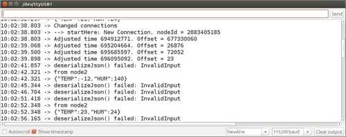
The failing to deserialize error turned out to not to be caused by the code on the touchpin board, but by the code on the receiving board (NodeMCU). That was still running the code of the first test with the humidity sensor. When I replaced it with the example code from painlessMesh named ‘Basic’, it received the message and was able to deserialize it. (File > Examples > PainlessMesh > Basic).
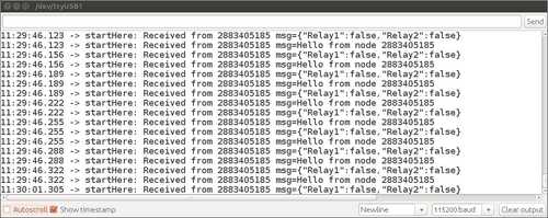
In this picture you can see the output on the serial monitor. The ‘hello from node [nodeID]’ message is what I want to have. But node2 is also still receiving the status of the pin (Relay1, etc.) and that needs to be removed. For my own reference: this stage is captured in code version 6: node1bar-v6.ino.
And then I get it to work. Node2 only receives messages when touchpin is touched. And the occasional network messages but that is good. That way you can see the status of the network. Now I am going to clean up my code. For my own reference: this stage is captured in code version 7: node1bar-v7.ino.
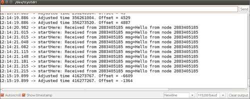
Note that not all touchpins seem to have the same threshold, so it may seem they do not work. It also seems that if you add more touchpins, the threshold per touch pin may change. So when TO1 is sensitive with 2 pins it may become less sensitive with 4. Fiddling with int threshold = 40; may help. Setting it to 60 is too high. The pins become so sensitive that they will report being touched even if you don’t touch them. At 40 touchpins t2, T7 and T3 work fine but T0 needs real hard pressing on the pin to register touch. Changing pins does not help.
I try to trick it by adding a 5th pin. This works indeed. No 4 pins are sensitive enough and print their output. But now touchpin1 (T1) registers as touchpin4 (T3). So when I press it it prints ‘touch 4 detected’ instead of ‘touch 1 detected’. Puzzling.
I change T1 to T5. Now, with 5 pins connected I get 4 readouts, one still does not work. But all 4 readouts are as they are declared in the code.
When making my own board I will break out some extra touch pins.
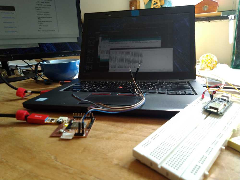
Here is the setup with the Barduino and the NodeMCU.
Video of setup and output on the serial monitor
Final code for node 1 with five touch pins in use:
// Code based on the ESP32 example code TouchInterupt and code from
// https://iotdesignpro.com/projects/creating-nodemcu-mesh-networking-using-esp12-and-arduino-ide

// Code for Node1:
#include "painlessMesh.h"   // include painlessMesh library


// WiFi Credentials
#define   MESH_PREFIX     "Post-collapseNetwork"
#define   MESH_PASSWORD   "TechnoLogic"
#define   MESH_PORT       5555

int threshold = 40;    // setting threshold for detecting touch on pin
bool touch1detected = false;
bool touch2detected = false;
bool touch3detected = false;
bool touch4detected = false;
bool touch5detected = false;

//Pin Declaration
#define touchPin1 T5  // declaring touch pins
#define touchPin2 T2 //Touchpin numberbering can be found at https://gitlab.fabcloud.org/barcelonaworkshops/barduino-2.0/
#define touchPin3 T7
#define touchPin4 T3
#define touchPin5 T0

Scheduler userScheduler; // calling on the scheduler to control your personal task. This replaces 'delay' function which messes up painlessMesh
painlessMesh  mesh;  // calling on painlessMesh

void sendMessage() ;  // Prototype so PlatformIO doesn't complain
Task taskSendMessage( TASK_SECOND * 1 , TASK_FOREVER, &sendMessage );  // this command replaces the 'delay' function
void sendMessage()
{
// Reading Status of touchPin
  if (digitalRead(touchPin1) == HIGH)
    touch1detected = !touch1detected;  // creates container to put status of pin in.
  if (digitalRead(touchPin2) == HIGH)
    touch2detected = !touch2detected;
  if (digitalRead(touchPin3) == HIGH)
    touch3detected = !touch3detected;
  if (digitalRead(touchPin4) == HIGH)
    touch4detected = !touch4detected;
  if (digitalRead(touchPin5) == HIGH)
    touch5detected = !touch5detected;

// Serializing in JSON Format
  DynamicJsonDocument doc(1024);
  doc["Relay1"] = touch1detected; // container created above is made into a doc named Relay1 file.
  doc["Relay2"] = touch2detected; // container created above is made into a doc named Relay2 file.
  doc["Relay3"] = touch3detected;
  doc["Relay4"] = touch4detected;
  doc["Relay5"] = touch4detected;
  String msg ;
  serializeJson(doc, msg);   //
    }


// Needed for painless library
void receivedCallback( uint32_t from, String &msg ) {
  Serial.printf("startHere: Received from %u msg=%s\n", from, msg.c_str());
}

void newConnectionCallback(uint32_t nodeId) {
  Serial.printf("--> startHere: New Connection, nodeId = %u\n", nodeId);
}
void changedConnectionCallback() {
  Serial.printf("Changed connections\n");
}
void nodeTimeAdjustedCallback(int32_t offset) {
  Serial.printf("Adjusted time %u. Offset = %d\n", mesh.getNodeTime(), offset);
}

void gotTouch1(){
 touch1detected = true;
}
void gotTouch2(){
 touch2detected = true;
}
void gotTouch3(){
 touch3detected = true;
}
void gotTouch4(){
 touch4detected = true;
}
void gotTouch5(){
 touch4detected = true;
}


void setup() {
  Serial.begin(115200);
  touchAttachInterrupt(T5, gotTouch1, threshold);  // checks if touchpin is interupted
  touchAttachInterrupt(T2, gotTouch2, threshold);
  touchAttachInterrupt(T7, gotTouch3, threshold);
  touchAttachInterrupt(T3, gotTouch4, threshold);
  touchAttachInterrupt(T0, gotTouch4, threshold);
  mesh.setDebugMsgTypes( ERROR | STARTUP );  // set before init() so that you can see startup messages
  mesh.init( MESH_PREFIX, MESH_PASSWORD, &userScheduler, MESH_PORT );
  mesh.onReceive(&receivedCallback);
  mesh.onNewConnection(&newConnectionCallback);
  mesh.onChangedConnections(&changedConnectionCallback);
  mesh.onNodeTimeAdjusted(&nodeTimeAdjustedCallback);
  userScheduler.addTask( taskSendMessage );
  taskSendMessage.enable();
}
void loop() {
    mesh.update();

  if(touch1detected){
    touch1detected = false;
    Serial.println("Touch 1 detected");

    sendMessage();   // Broadcasting message
    String msg = ".";
    mesh.sendBroadcast( msg );
}

  if(touch2detected){
    touch2detected = false;
    Serial.println("Touch 2 detected");

  sendMessage();
    String msg = "-";
    mesh.sendBroadcast( msg );
  }

 if(touch3detected){
    touch3detected = false;
    Serial.println("Touch 3 detected");

  sendMessage();
    String msg = "/";
    mesh.sendBroadcast( msg );
 }

 if(touch4detected){
    touch4detected = false;
    Serial.println("Touch 4 detected");

  sendMessage();
    String msg = " ";
    mesh.sendBroadcast( msg );
 }
 if(touch5detected){
    touch5detected = false;
    Serial.println("Touch 5 detected");

  sendMessage();
    String msg = " ";
    mesh.sendBroadcast( msg );
 }
}
Final code for node2 (the basic example from the PainlessMesh library)
//************************************************************
// this is a simple example that uses the painlessMesh library
//
// 1. sends a silly message to every node on the mesh at a random time between 1 and 5 seconds
// 2. prints anything it receives to Serial.print
//
//
//************************************************************
#include "painlessMesh.h"

#define   MESH_PREFIX     "Post-collapseNetwork"
#define   MESH_PASSWORD   "TechnoLogic"
#define   MESH_PORT       5555

Scheduler userScheduler; // to control your personal task
painlessMesh  mesh;

// User stub
void sendMessage() ; // Prototype so PlatformIO doesn't complain

Task taskSendMessage( TASK_SECOND * 1 , TASK_FOREVER, &sendMessage );

void sendMessage() {
  String msg = "Hello from node ";
  msg += mesh.getNodeId();
  mesh.sendBroadcast( msg );
  taskSendMessage.setInterval( random( TASK_SECOND * 1, TASK_SECOND * 5 ));
}

// Needed for painless library
void receivedCallback( uint32_t from, String &msg ) {
  Serial.printf("startHere: Received from %u msg=%s\n", from, msg.c_str());
}

void newConnectionCallback(uint32_t nodeId) {
    Serial.printf("--> startHere: New Connection, nodeId = %u\n", nodeId);
}

void changedConnectionCallback() {
  Serial.printf("Changed connections\n");
}

void nodeTimeAdjustedCallback(int32_t offset) {
    Serial.printf("Adjusted time %u. Offset = %d\n", mesh.getNodeTime(),offset);
}

void setup() {
  Serial.begin(115200);

//mesh.setDebugMsgTypes( ERROR | MESH_STATUS | CONNECTION | SYNC | COMMUNICATION | GENERAL | MSG_TYPES | REMOTE ); // all types on
  mesh.setDebugMsgTypes( ERROR | STARTUP );  // set before init() so that you can see startup messages

  mesh.init( MESH_PREFIX, MESH_PASSWORD, &userScheduler, MESH_PORT );
  mesh.onReceive(&receivedCallback);
  mesh.onNewConnection(&newConnectionCallback);
  mesh.onChangedConnections(&changedConnectionCallback);
  mesh.onNodeTimeAdjusted(&nodeTimeAdjustedCallback);

  userScheduler.addTask( taskSendMessage );
  taskSendMessage.enable();
}

void loop() {
  // it will run the user scheduler as well
  mesh.update();
}
Programming for the OLED monitor
The OLED monitor is communicates to the board over I2C. Therefore it needs an address. The address for my OLED is 0x3C. This must be entered in any code regarding the OLED.
Note: I’ve made a change in the Adafruit library for the OLED. I’ve used the library already and it works with my OLED. But on the internet people recommended changing a line in the library. By default, the OLED that is addressed by the library is the SSD1306_128_32. But I have a SSD1306_128_64. 128x64 refers to the size of the screen. By default the line #define SSD1306_128_32 is uncommented by default and the line #define SSD1306_128_64. is commented. I reversed that, commented the 32 line and uncommented the 64 line.
Desiging the ESP32 board
Powering the board
Henk explained some things on adding batteries to your board. I thought you had to add extra pads to a boards design to connect a battery. But Henk provided a much better idea. You can link your battery’s GND and VCC to the GND and VCC of the FTDI. This has two benefits. First, it saves extra components on the board. And two, it will prevent me from accidently powering on the battery and plugging in the FTDI. That will probably fry my board. So with that, the search on how to physically add a battery to my project is solved.
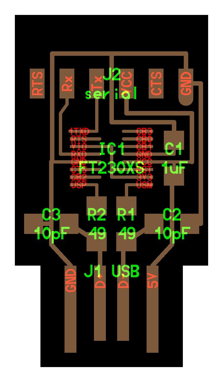 Here is the schematic of the FTDI. It shows the GND and VCC of the FTDI header. So the battery’s GND should be connected to pin1 of the FTDI header and VCC to pin3.
The second question is what battery to use for your project. Volts are rather straight forward. My project is entirely 3.3V. The ESP32 wants 3.3V and so does the OLED monitor. So I need Voltage supply of 3.3V or more. More voltage is not a problem because the ESP32 board has a voltage regulator on it. Above I linked to the datasheet of the voltage regulator. In it it states that the regulator can take up to 20Volt as input. I want to use AA batteries which usually have 1.5V. You can align them in serial and then you can add up the voltage. So, three AA batteries would supply 4.5V.
Next up is the question of how much Ampere the board uses. Henk showed is how to measure that. You hook up your board to a power bench (via the FTDI VCC and GND pins). You put the voltage on what you will provide to the board. Henk set it to 5V. Then you put the Ampere on a setting, we used 0.5 milliAmpere. Now on the display of the power bank you can see how much milliAmpere is drawn by the board. Connecting the ESP32board while it was running Blink code draws 0.035 milliAmpere. Now you can calculate how long the board will run on a particular battery. Say you have a battery of 300mAmp/h and your project draws 0.300 mAmp, the board can run on this battery for an hour.
Here is an overview of milliampere on AA batteries.
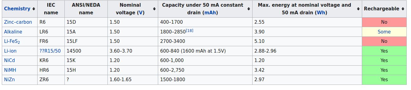
Source: Wikipedia.
Components
Components I will add to my design:
1. The Barduino has pin that runs to the VCC trace. This pin can be used to provide power to a module. Since I want to run the OLED board on my ESP32 board, I want to add this pin to my board too.
2. I will break out 6 touch pins. I need 4 but as described above a 5th is needed to trick the code. And I will add 2 extra in case some pins throw errors like they did with the Barduino.
Component list
| component | quantity |
|---|---|
| ESP-32WROOM | 1 |
| Voltage regulator LM117-3.3 /SOT-223 | 1 |
| capacitor 10uF | 2 |
| capacitor 0.1 uF | 1 |
| LED green | 2 |
| Resistor 100-ohm | 2 |
| Resistor 10k-ohm | 1 |
| Resistor 0-ohm | 1 |
| FTDI 6-pin header | 1 |
| Pin header 2x2 | 3 |
| Slide switch | 1 |
| Push button | 1 |
Pins to break out
The following pins need to be broken out for my purposes. I use this pinout schema of the ESP32WROOM.
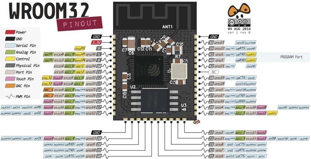
For the OLED monitor I need a GND pin to provide power. This can be established by routing a trace from Vout of the voltage regulator to a pin. I also need GND which is delivered by the GND pin of the ESP32.
For I2C I need to pins to assign SDA and SCL to. Here is a tutorial that shows which pins of the ESP32 can be used for SCL and SDA. You can also use other pins for this but I’ll stick to that schema. SDA goes to GPIO21 (pin 42) and SCL to GPIO22 (pin 39).
As described above I will break out 8 touchpins (Tx). For routing purposes I’ll cluster them in two pairs of four.
I wanted to use T1 (GPIO0) but I see that that needs to be used for the program switch. So instead of that pin I will use T9 (GPIO32).
The primary cluster of four pins consists of T6 (GPIO14), T7 (GPIO27), T8 (GPIO33) and T9 (GPIO32). As back up touchpins I will break out T2 (GPIO2).
GPIO13 will be used for one of the two LEDs.
| Pins | routed from |
|---|---|
| V3.3 | Vout voltage regulator |
| GND | GND pin on the ESP32 |
| SDA | GPIO21 (pin 42) (they are to the left and right of the RX&TX pins) |
| SCL | GPIO22 (pin 39) |
| T6 | GPIO14 |
| T7 | GPIO27 |
| T8 | GPIO33 |
| T9 | GPIO32 |
| T2 | GPIO2 |
| T3 | GPIO15 |
| Slide switch | GPIO0 |
| LED 2 | GPIO13 |
KiCad
Footprints
The footprint for the voltage regulator I already found when doing the board for the ESP8266. It is called the to_sot_packages_SMD.pretty-master and can be found on Github. On my own computer it is in FabAcademy > KiCad libraries. The footprint is called: SOT-223-3_TabPin2.
I found the footprint for the ESP32 for KiCad here. I’d advise not to use that library. For me the pads for the ESP came out all connected to each other, rather than separated. See the description below under milling.
Push button
I was unsure about the push button. In my design I have one leg running to GND and the other leg is not connected. I asked Henk. He showed me how it works with a multimeter. When you press the button down the two legs are connected. You can test that with the multimeter sound setting. So when you press the button, both legs will be pulled to GND. So there is no reason to attach both legs to GND.
EEschema and PCB new
Here is the EEschema:
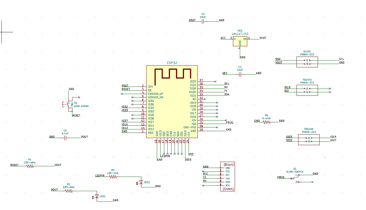
And here the PCBnew:
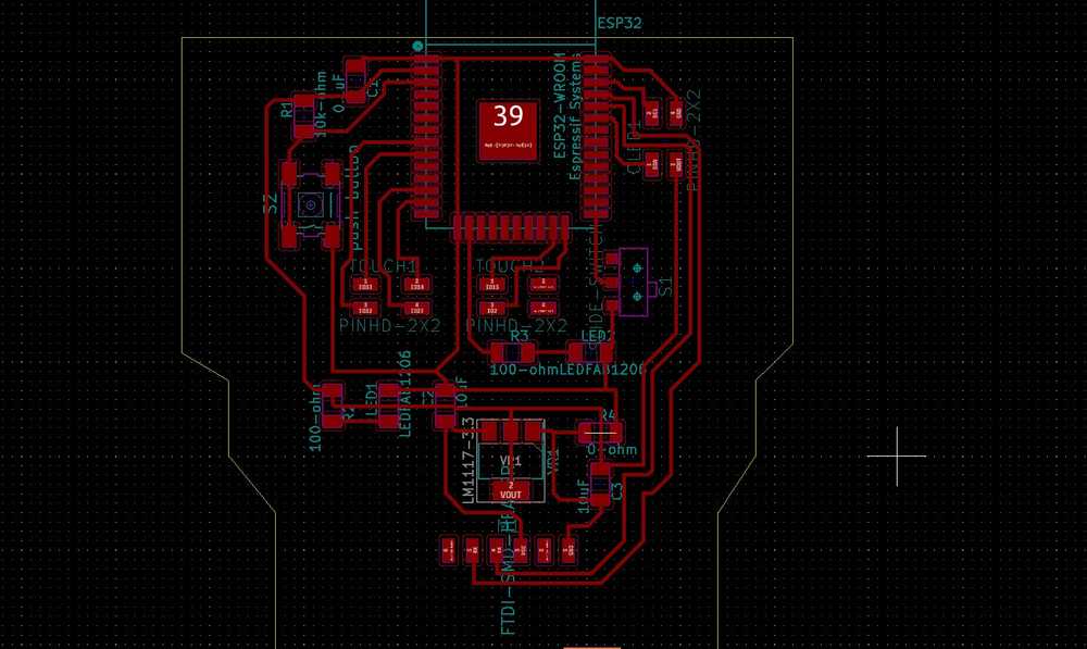
Milling
I used a footprint for the ESP32 downloaded from the internet. That did not work well for me. The pads for the ESP came out all connected to each other, rather than separated.
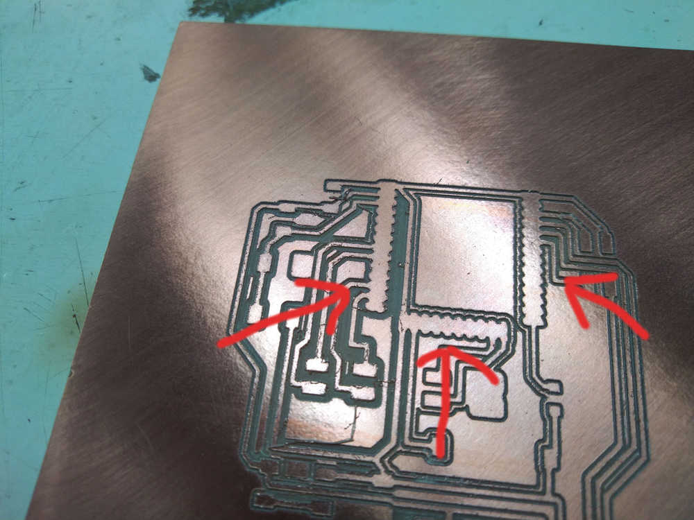
My class mates did not have this problem. As it turned out there is a KiCad fab library that includes the ESP32. But my KiCad fab library did not. Appearantly there are two libraries. I looked here where I found the fab library I installed in week06. But there I only see one library. In the end my class mates Nathan gave me a copy of the other library which includes the footprint for the ESP32.
The source files for this board at the top of the page include the new, correct footprint. Since I don’t know where to find it on the internet and can not link to it I also included the library in my source files at the top of this page.
Henk later told me where I could have checked this. In Mods you can see the outline where the drill is going to mill. I could have seen there that the mill was not milling between the pads.
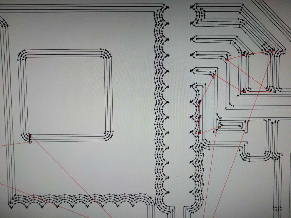 Wrong: no milling between the pads.
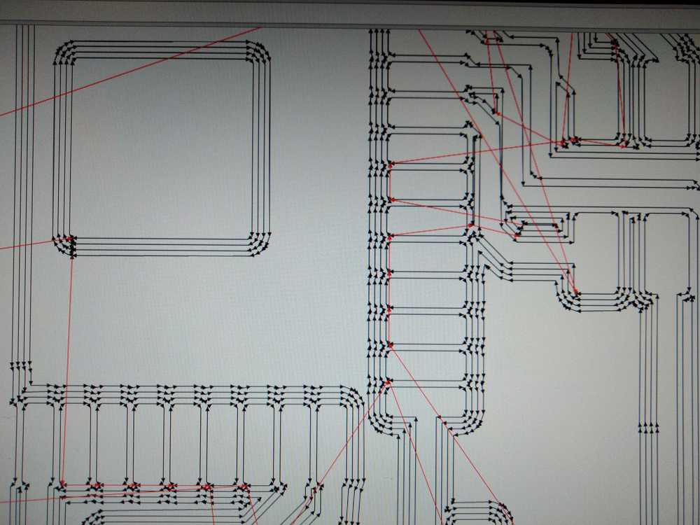 Right: milling between the pads.
During cutout the drill came loose from its socket. I had failed to turn the fastening screw tight. Luckily the drill survived.
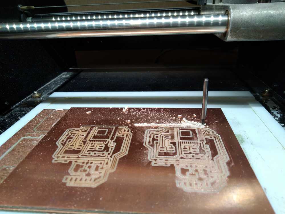
The board comes out like this:
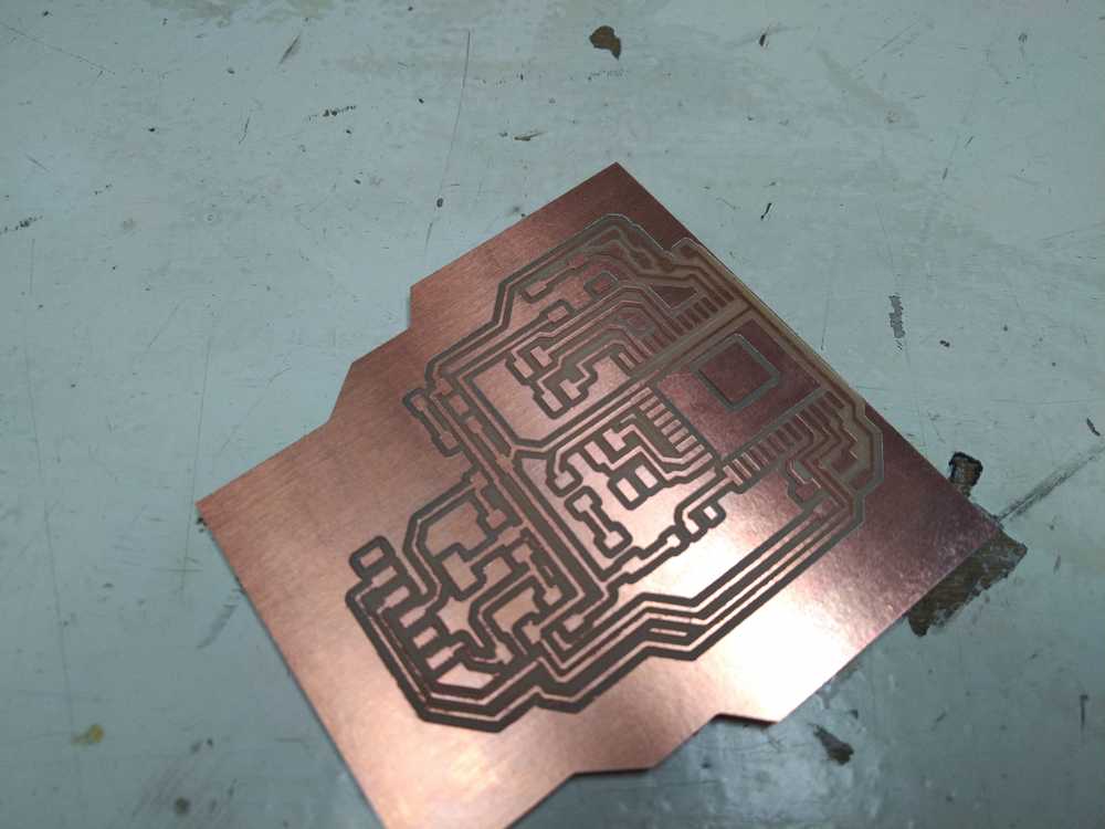
And the populated board:
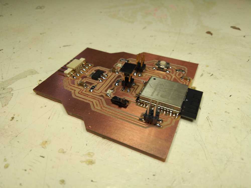
Working board
It blinks!
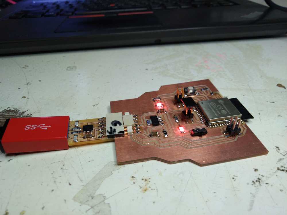
I upload the code I made earlier for the Barduino. And it works :). When the slide switch is switched to GND the chip is in programming mode. (This is switching the slide toward the FTDI header.)
It establishes a mesh network:
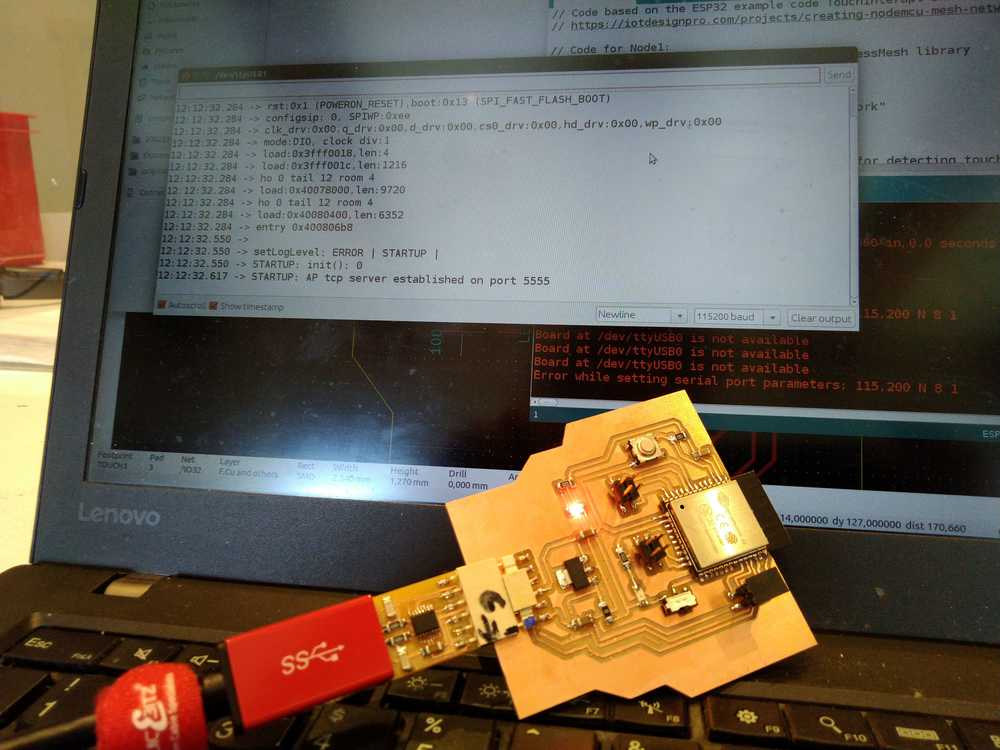
Receives messages from the NodeMCU:
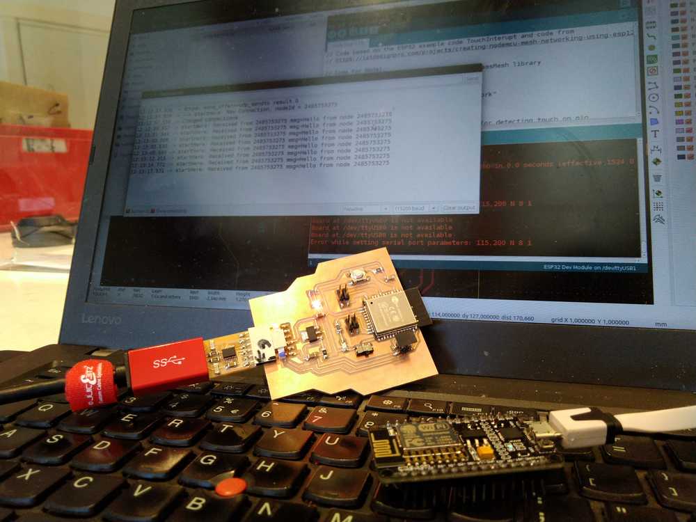
Touch pins work as well. In the picture touch and messages from the NodeMCU are both registered in the serial monitor.

Programming for the OLED monitor
My goal is to display the morse code on the monitor. In the first spiral I want the monitor to display characters on the monitor when they are typed in. In the second spiral I want to also display the characters on the monitor when they are received from another node.
touchpins combined with oled
This is code version one. The touchpins work, the OLED works. But touching the pins does not trigger an event on the OLED.
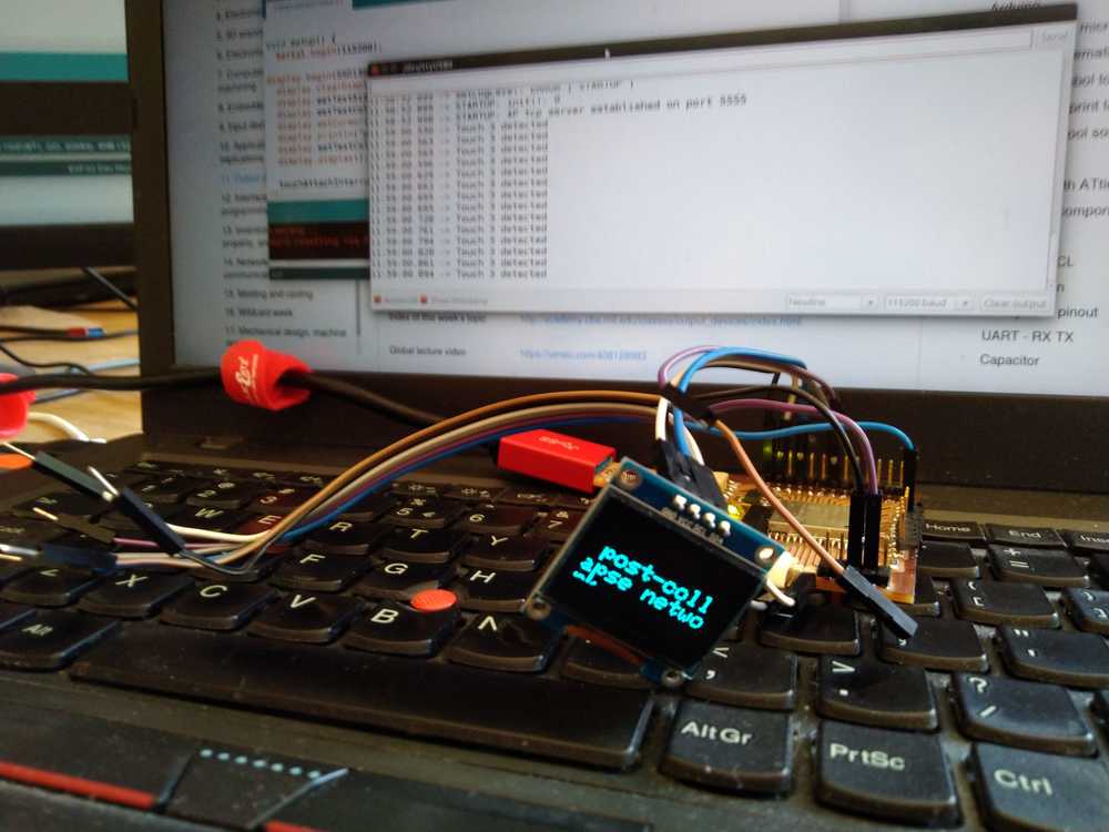
// Code based on the ESP32 example code TouchInterupt and code from
// https://iotdesignpro.com/projects/creating-nodemcu-mesh-networking-using-esp12-and-arduino-ide

// Code for Node1:
#include "painlessMesh.h"   // include painlessMesh library
#include <ArduinoJson.h>
#include <SPI.h>
#include <Wire.h>
#include <Adafruit_GFX.h>
#include <Adafruit_SSD1306.h>


// WiFi Credentials
#define   MESH_PREFIX     "Post-collapseNetwork"
#define   MESH_PASSWORD   "TechnoLogic"
#define   MESH_PORT       5555

#define SCREEN_WIDTH 128 // OLED display width, in pixels
#define SCREEN_HEIGHT 64 // OLED display height, in pixels

// Necessary for OLED Display
#define OLED_RESET     -1 // Reset pin # (or -1 if sharing Arduino reset pin)
Adafruit_SSD1306 display(SCREEN_WIDTH, SCREEN_HEIGHT, &Wire, OLED_RESET);

int threshold = 23;    // setting threshold for detecting touch on pin
bool touch1detected = false;
bool touch2detected = false;
bool touch3detected = false;
bool touch4detected = false;
bool touch5detected = false;

//Pin Declaration
#define touchPin1 T3  // declaring touch pins
#define touchPin2 T6 //Touchpin numberbering can be found at https://gitlab.fabcloud.org/barcelonaworkshops/barduino-2.0/
#define touchPin3 T7
#define touchPin4 T8
#define touchPin5 T5

Scheduler userScheduler; // calling on the scheduler to control your personal task. This replaces 'delay' function which messes up painlessMesh
painlessMesh  mesh;  // calling on painlessMesh

void sendMessage() ;  // Prototype so PlatformIO doesn't complain
Task taskSendMessage( TASK_SECOND * 1 , TASK_FOREVER, &sendMessage );  // this command replaces the 'delay' function
void sendMessage()
{
// Reading Status of touchPin
  if (digitalRead(touchPin1) == HIGH)
    touch1detected = !touch1detected;  // creates container to put status of pin in.
  if (digitalRead(touchPin2) == HIGH)
    touch2detected = !touch2detected;
  if (digitalRead(touchPin3) == HIGH)
    touch3detected = !touch3detected;
  if (digitalRead(touchPin4) == HIGH)
    touch4detected = !touch4detected;
  if (digitalRead(touchPin5) == HIGH)
    touch5detected = !touch5detected;

// Serializing in JSON Format
  DynamicJsonDocument doc(1024);
  doc["Relay1"] = touch1detected; // container created above is made into a doc named Relay1 file.
  doc["Relay2"] = touch2detected; // container created above is made into a doc named Relay2 file.
  doc["Relay3"] = touch3detected;
  doc["Relay4"] = touch4detected;
  doc["Relay5"] = touch5detected;
  String msg ;
  serializeJson(doc, msg);   //
    }


// Needed for painless library
void receivedCallback( uint32_t from, String &msg ) {
  Serial.printf("startHere: Received from %u msg=%s\n", from, msg.c_str());
}

void newConnectionCallback(uint32_t nodeId) {
  Serial.printf("--> startHere: New Connection, nodeId = %u\n", nodeId);
}
void changedConnectionCallback() {
  Serial.printf("Changed connections\n");
}
void nodeTimeAdjustedCallback(int32_t offset) {
  Serial.printf("Adjusted time %u. Offset = %d\n", mesh.getNodeTime(), offset);
}

void gotTouch1(){
 touch1detected = true;
}
void gotTouch2(){
 touch2detected = true;
}
void gotTouch3(){
 touch3detected = true;
}
void gotTouch4(){
 touch4detected = true;
}
void gotTouch5(){
 touch5detected = true;
}


void setup() {
  Serial.begin(115200);

display.begin(SSD1306_SWITCHCAPVCC, 0x3C);// initialize with the I2C addr 0x3D (for the 128x64)
  display.clearDisplay();
  display.setTextSize(2);
  display.setTextColor(WHITE);
  display.setCursor(10, 25);
  display.println("post-collapse network");
  display.setTextColor(WHITE); // 'inverted' text
  display.display();

  touchAttachInterrupt(T3, gotTouch1, threshold);  // checks if touchpin is interupted
  touchAttachInterrupt(T6, gotTouch2, threshold);
  touchAttachInterrupt(T7, gotTouch3, threshold);
  touchAttachInterrupt(T8, gotTouch4, threshold);
  touchAttachInterrupt(T5, gotTouch5, threshold);

  mesh.setDebugMsgTypes( ERROR | STARTUP );  // set before init() so that you can see startup messages
  mesh.init( MESH_PREFIX, MESH_PASSWORD, &userScheduler, MESH_PORT );
  mesh.onReceive(&receivedCallback);
  mesh.onNewConnection(&newConnectionCallback);
  mesh.onChangedConnections(&changedConnectionCallback);
  mesh.onNodeTimeAdjusted(&nodeTimeAdjustedCallback);
  userScheduler.addTask( taskSendMessage );
  taskSendMessage.enable();
}
void loop() {
    mesh.update();

  if(touch1detected){
    touch1detected = false;
    Serial.println("Touch 1 detected");
    display.print("T1");

    sendMessage();   // Broadcasting message
    String msg = ".";
    mesh.sendBroadcast( msg );
}

  if(touch2detected){
    touch2detected = false;
    Serial.println("Touch 2 detected");
    display.print("T2");

  sendMessage();
    String msg = "-";
    mesh.sendBroadcast( msg );
  }

 if(touch3detected){
    touch3detected = false;
    Serial.println("Touch 3 detected");

  sendMessage();
    String msg = "/";
    mesh.sendBroadcast( msg );
 }

 if(touch4detected){
    touch4detected = false;
    Serial.println("Touch 4 detected");

  sendMessage();
    String msg = " ";
    mesh.sendBroadcast( msg );
 }
 if(touch5detected){
    touch5detected = false;
    Serial.println("Touch 5 detected");

  sendMessage();
    String msg = " ";
    mesh.sendBroadcast( msg );
 }
}
Touchpins trigger event on oled
Version 2 of the code does trigger an event on the OLED when the touchpin is triggered. But after shortly displaying the message defined, the OLED goes black. Probably because I have the function clear display in the loop. But I think that is needed to clear the display every once in a while. What I am missing is the delay function. Often used in Arduino code but it can’t be used together with painless mesh. Instead painless uses TaskSchedular. On this page is explainde how TaskScheduler works.
It explains what to do instead of the delay function: instead of:
void callback() {
... stuff
delay(1000);
... more stuff
}
do this:
void callback1() {
... stuff
t1.setCallback(&callback2);
t1.delay(1000);
}
void callback2() {
... more stuff
t1.setCallback(&callback1);
}
I try to refresh the oled by adding a task to the code. This is based on the example code from the TaskeScheduler library.
C```
void t2Callback();
Task t2(3000, TASK_FOREVER, &t2Callback);
void t2Callback() {
display.clearDisplay();
}
And adding to `void setup`
```C
userScheduler.init();
userScheduler.addTask(t2);
delay(5000);
t2.enable();
And adding to void loop
userScheduler.execute();
But it does not work. I looked at the code from these projects with painlessMesh and TaskScheduler: two way communication and TaskScheduler and oled.
Touchpins, oled and refreshing the monitor
I then realized that I could go at this another way. The screen needs to refresh and so far I have been trying to get the screen to refresh in looped intervals. But the Adafruit library contains a commands display.setCursor(0, 0);. It places the cursor at the start of the monitor. A better way to refresh the screen is to tell the screen to refresh when the cursor reaches the end of the screen.
At this point my friend Filip came over and we looked at the code together. Filip knew something I have been wanting to know for a while: how to find what commands are included in the library. The best way is if its documented properly. You can find this by searching for the name of the library and a function used in the library. For instance: ‘adafruit GFX library’ and ‘setcursor’. That landed us on a Github page where all the functions are described. And here is the Adafruit SSD1306 library page.
First we looked for the easiest function: a scroll function. But the library only has scrolling from left to right.
So then we went on to implement the idea of refreshing when the cursor hits a position at the end of a page.
The library has the functions: getCursorX and getCursorY. This outputs the position of the cursor to the serial monitor. When the cursor is almost at it last position on the screen the Y value is 53.
int cursorY=display.getCursorY();
    Serial.println(cursorY);
This is followed by a if > then function:
if(cursorY>53){
display.clearDisplay();
display.setCursor(0, 0);
And all of this is summarized in a void:
void checkDisplay(){
int cursorY=display.getCursorY();
Serial.println(cursorY);
if(cursorY>53){
  display.clearDisplay();
  display.setCursor(0, 0);
    }

}
Now the display.clearDisplay finally worked. I also saw something I did wrong in the previous tries. I had omitted to at the line display.setCursor(0, 0);. So I did get the screen to refresh but I never told it to start at the top again. When using the getCursor command you can see by the count in the serial monitor that each new statement is written on a new line. It never returns to the start if you don’t tell the cursor to start at the beginning again.
Display received message on oled
The final thing I want my program to do is to display incoming messages on the oled. After having figured out to output the touchpins on the monitor this was quickly done.
After the command from painlessMesh on receiving a message:
void receivedCallback( uint32_t from, String &msg ) {
Serial.printf("startHere: Received from %u msg=%s\n", from, msg.c_str());
I added:
checkDisplay();
display.print(msg.c_str());
display.display();
The final code is:
// Code based on the ESP32 example code TouchInterupt and code from
// https://iotdesignpro.com/projects/creating-nodemcu-mesh-networking-using-esp12-and-arduino-ide
//Touchpin numberbering can be found at https://gitlab.fabcloud.org/barcelonaworkshops/barduino-2.0/
// Program runs painlessMesh to create a mesh network
// Operates 5 touchpins. When pin is touched a message is send to both the serial monitor and the oled monitor
// When a message is received it outputs to both serial and oled monitor.
// position of cursor is communicated to the monitor.
// When cursor is at the end of the monitor, display.cleardisplay is triggered.


// Code for Node1:
#include "painlessMesh.h"   // include painlessMesh library
#include <ArduinoJson.h>
#include <SPI.h>
#include <Wire.h>
#include <Adafruit_GFX.h>
#include <Adafruit_SSD1306.h>


// WiFi Credentials
#define   MESH_PREFIX     "Post-collapseNetwork"
#define   MESH_PASSWORD   "TechnoLogic"
#define   MESH_PORT       5555

#define SCREEN_WIDTH 128 // OLED display width, in pixels
#define SCREEN_HEIGHT 64 // OLED display height, in pixels

// Necessary for OLED Display
#define OLED_RESET     -1 // Reset pin # (or -1 if sharing Arduino reset pin)
Adafruit_SSD1306 display(SCREEN_WIDTH, SCREEN_HEIGHT, &Wire, OLED_RESET);

int threshold = 17; // setting threshold for detecting touch on pin
// int threshold2 = 99;
bool touch1detected = false;
bool touch2detected = false;
bool touch3detected = false;
bool touch4detected = false;
bool touch5detected = false;
bool touch6detected = false;

//Pin Declaration
#define touchPin1 T2  // declaring touch pins
#define touchPin2 T6
#define touchPin3 T7
#define touchPin4 T8
#define touchPin5 T3
#define touchPin6 T5

Scheduler userScheduler; // calling on the scheduler to control your personal task. This replaces 'delay' function which messes up painlessMesh
painlessMesh  mesh;  // calling on painlessMesh

void sendMessage() ;  // Prototype so PlatformIO doesn't complain
Task taskSendMessage( TASK_SECOND * 1 , TASK_FOREVER, &sendMessage );  // this command replaces the 'delay' function
void sendMessage()
{
// Reading Status of touchPin
  if (digitalRead(touchPin1) == HIGH)
    touch1detected = !touch1detected;  // creates container to put status of pin in.
  if (digitalRead(touchPin2) == HIGH)
    touch2detected = !touch2detected;
  if (digitalRead(touchPin3) == HIGH)
    touch3detected = !touch3detected;
  if (digitalRead(touchPin4) == HIGH)
    touch4detected = !touch4detected;
  if (digitalRead(touchPin5) == HIGH)
    touch5detected = !touch5detected;
  if (digitalRead(touchPin6) == HIGH)
    touch6detected = !touch6detected;

// Serializing in JSON Format
  DynamicJsonDocument doc(1024);
  doc["Relay1"] = touch1detected; // container created above is made into a doc named Relay1 file.
  doc["Relay2"] = touch2detected; // container created above is made into a doc named Relay2 file.
  doc["Relay3"] = touch3detected;
  doc["Relay4"] = touch4detected;
  doc["Relay5"] = touch5detected;
  doc["Relay6"] = touch6detected;
  String msg ;
  serializeJson(doc, msg);   //
    }


// Needed for painless library
void receivedCallback( uint32_t from, String &msg ) {
  Serial.printf("startHere: Received from %u msg=%s\n", from, msg.c_str());
  checkDisplay();
  display.print(msg.c_str());
  display.display();
}

void newConnectionCallback(uint32_t nodeId) {
  Serial.printf("--> startHere: New Connection, nodeId = %u\n", nodeId);
}
void changedConnectionCallback() {
  Serial.printf("Changed connections\n");
}
void nodeTimeAdjustedCallback(int32_t offset) {
  Serial.printf("Adjusted time %u. Offset = %d\n", mesh.getNodeTime(), offset);
}

void gotTouch1(){
 touch1detected = true;
}
void gotTouch2(){
 touch2detected = true;
}
void gotTouch3(){
 touch3detected = true;
}
void gotTouch4(){
 touch4detected = true;
}
void gotTouch5(){
 touch5detected = true;
}
void gotTouch6(){
 touch6detected = true;
}


void setup() {
  Serial.begin(115200);

  display.begin(SSD1306_SWITCHCAPVCC, 0x3C);// initialize with the I2C addr 0x3C (for the 128x64)
  display.clearDisplay();
  display.setTextSize(1);
  display.setTextColor(WHITE);
  display.setCursor(0, 0);
  display.println("post-collapse network");
  display.setTextSize(2);
  display.setCursor(0, 15);
  display.print("Message: ");
  display.setTextColor(WHITE); // 'inverted' text
  display.display();   //you have to tell the display to...display

  touchAttachInterrupt(T2, gotTouch1, threshold);  // checks if touchpin is interupted
  touchAttachInterrupt(T6, gotTouch2, threshold);
  touchAttachInterrupt(T7, gotTouch3, threshold);
  touchAttachInterrupt(T8, gotTouch4, threshold);
  touchAttachInterrupt(T3, gotTouch5, threshold);
  touchAttachInterrupt(T5, gotTouch6, threshold);

  mesh.setDebugMsgTypes( ERROR | STARTUP );  // set before init() so that you can see startup messages
  mesh.init( MESH_PREFIX, MESH_PASSWORD, &userScheduler, MESH_PORT );
  mesh.onReceive(&receivedCallback);
  mesh.onNewConnection(&newConnectionCallback);
  mesh.onChangedConnections(&changedConnectionCallback);
  mesh.onNodeTimeAdjusted(&nodeTimeAdjustedCallback);
  userScheduler.addTask( taskSendMessage );
  taskSendMessage.enable();
}

void checkDisplay(){
   // int cursorX=display.getCursorX();
   // Serial.println(cursorX);
    int cursorY=display.getCursorY();
    Serial.println(cursorY);
    if(cursorY>53){
      display.clearDisplay();
      display.setCursor(0, 0);
    }

}


void loop() {
    mesh.update();


  if(touch1detected){
    touch1detected = false;
    checkDisplay();
    Serial.println("Touch 1 detected");
    display.print("/");
    display.display();

    sendMessage();   // Broadcasting message
    String msg = "/";
    mesh.sendBroadcast( msg );
}

  if(touch2detected){
    touch2detected = false;
    checkDisplay();
    Serial.println("Touch 2 detected");
    display.print("-");
    display.display();

  sendMessage();
    String msg = "-";
    mesh.sendBroadcast( msg );
  }

 if(touch3detected){
    touch3detected = false;
    checkDisplay();
    Serial.println("Touch 3 detected");
    display.print(" ");
    display.display();

  sendMessage();
    String msg = " ";
    mesh.sendBroadcast( msg );
 }

 if(touch4detected){
    touch4detected = false;
    checkDisplay();
    Serial.println("Touch 4 detected");
    display.print(".");
    display.display();

  sendMessage();
    String msg = ".";
    mesh.sendBroadcast( msg );
 }
 if(touch5detected){
    touch5detected = false;
    checkDisplay();
    Serial.println("Touch 5 detected");
    display.print("/");
    display.display();

  sendMessage();
    String msg = "/";
    mesh.sendBroadcast( msg );
 }

 if(touch6detected){
    touch6detected = false;
    checkDisplay();
    Serial.println("Touch 6 detected");
    display.print("/");
    display.display();

  sendMessage();
    String msg = "/";
    mesh.sendBroadcast( msg );
 }
}
Output on the monitor. When a message is received from another node it is outputted on the oled (Hello from node…). When touchpin 2 is touched T2 is outputted on the monitor.
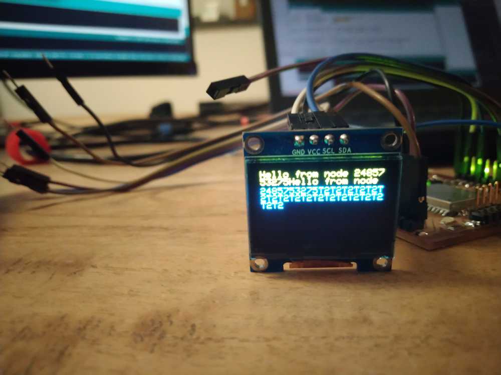
Touchpin triggers output on the monitor
Hello from node 2 outputs on the monitor.
Local lecture
We discuss three types of communication:
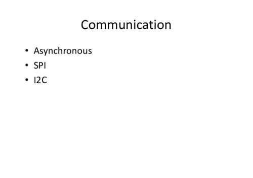
Asynchronous serial:
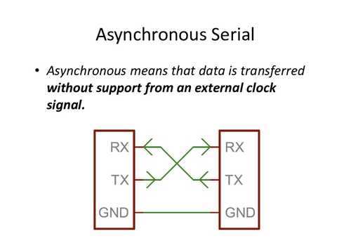
RX TX: data is transferred without an external clock. It is basic and always works. Most machines in the Lab use asynchronous serial communication.
No clock means that you have to set op rules. Together they are called a protocol.
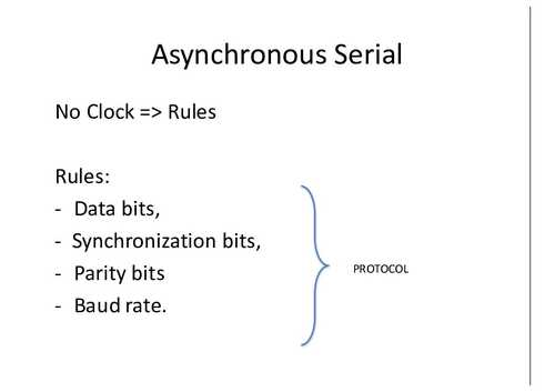
Rules are about:
Data bits
Synchronyzation bits
Parity bits: checking if the bits that came in are okay. can be done in hardware or in software.
Baud rate: bits per second. For instance 9600 per second.

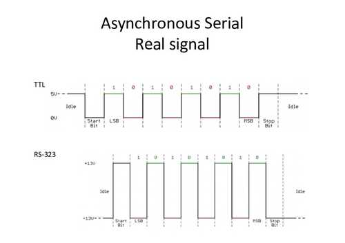
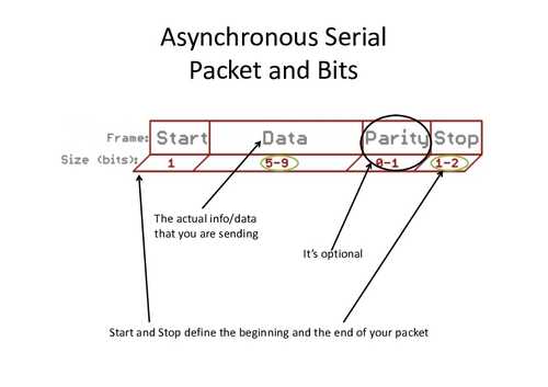
TTL:
RS-323
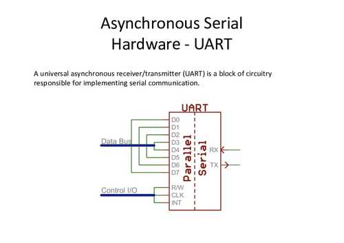
Uart: hardware: a block of circuitry responsible for implementing serial communication. If there is no hardware UART you can do it by bit-banging. For instance when you use the softwareSerial library.
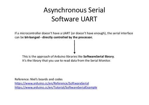
Asynchronous serial network:
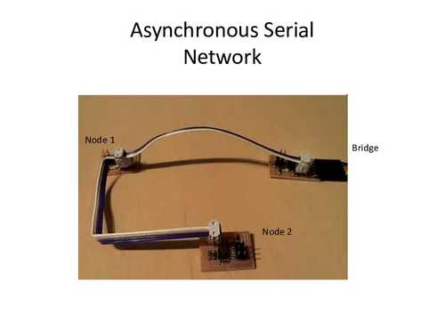
Four wires: VCC, GND, and an RX and TX. The nodes need to have an address. Problem of asynchronous is you need to hard program the data speed because devices can’t negotiate over it.
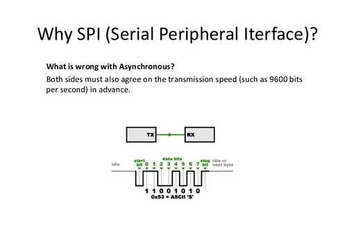
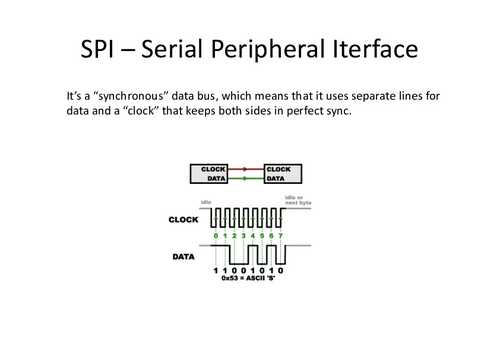
SPI: Serial Peripheral Interface.
It’s a synchronous data bus which means that it uses separate lines for data and a clock that keeps both sides in perfect sync. SPI had clock pinouts and data pinouts.
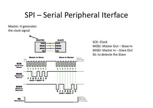
SCK: Clock
MOSI: Master Out - Slave In
MISO: Master In - Slave Out
SS: Slave Select: to detecte the slave.
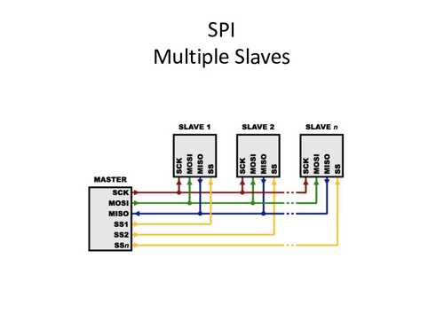
SPI can have multiple children addressed.
SPI can be a mess fo cables when you want to connect many children.
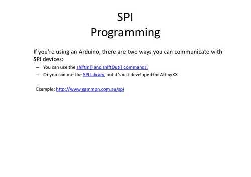
I2C

I2C Most Attiny’s have SDA/SDL ports. Very basic protocol. You have a 7 bit address, 8 bits of data.
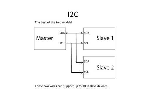
Only with two wires you can connect 1008(!) devices.
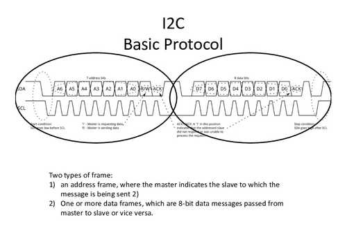
Two data frames: one to say the address to indicate which child is addressed. And then one or more data frames that is sending the data. The data frames consist of bytes. Each bit in byte has a function like ack etc.

There is a start condition and a stop condition
The parent device leaves SDL high and pulls SDA low: children know that they should listen.
Start condition: SDA goes low before SCL. 1 parent is requesting data. 0 parent is sending data.
Stop condition SDA goes high after SCL.
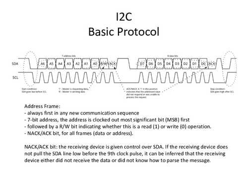
NACK/ACK: the receiving device is given control over SDA.
Data Frames: data can begin being transmitted. The parent will simply continue generating clock pulses at a regular interval, and the data will be placed on SDA by either the parent or the child, depending on whether the R/W bit indicated a read or write operation.
Stop condition: Once all the data frames have been sent, the parent will generate a stop condition. Stop conditions are defined by a 0->1 (low to high) transition on SDA after a 0->1 transition on SCL, with SCL remaining high.
Reference:
-Neil’s boards and codes
-Arduino Libraries, Attiny44:
- TinyWireM
- TinyWireS ex: http://fabacademy.org/archives/2014/students/nabil.aser/Week13_networking%20and%20communications.html
- Arduino Libraries, AtMega328P:
- Wire https://www.arduino.cc/en/Reference/Wire
https://www.arduino.cc/en/Tutorial/MasterReader
http://www.gammon.com.au/i2c
SDA SDL pins are dedicated on the pinout. Look up in your diagram which pins to use. (If needed you can do it on general IOpins but that is very hard.)
Group assignment
A full description of the group assignment can be found on our communual page
This week’s group assignment is: ‘send a message between two projects’.
Nathan and I did the group assignment together. We both have made a board using the ESP32 module. This is a WiFi enabled chip. So we used WiFi to connect to each other.
We linked our devices using the painlessMesh library. I had already have the library installed on the Arduino IDE and Nathan installed it too. I uploaded this code to my board:
// Code based on the ESP32 example code TouchInterupt and code from
// https://iotdesignpro.com/projects/creating-nodemcu-mesh-networking-using-esp12-and-arduino-ide
//Touchpin numberbering can be found at https://gitlab.fabcloud.org/barcelonaworkshops/barduino-2.0/
// Program runs painlessMesh to create a mesh network
// Operates 5 touchpins. When pin is touched a message is send to both the serial monitor and the oled monitor
// When a message is received it outputs to both serial and oled monitor.
// position of cursor is communicated to the monitor.
// When cursor is at the end of the monitor, display.cleardisplay is triggered.


// Code for Node1:
#include "painlessMesh.h"   // include painlessMesh library
#include <ArduinoJson.h>
#include <SPI.h>
#include <Wire.h>
#include <Adafruit_GFX.h>
#include <Adafruit_SSD1306.h>


// WiFi Credentials
#define   MESH_PREFIX     "Post-collapseNetwork"
#define   MESH_PASSWORD   "TechnoLogic"
#define   MESH_PORT       5555

#define SCREEN_WIDTH 128 // OLED display width, in pixels
#define SCREEN_HEIGHT 64 // OLED display height, in pixels

// Necessary for OLED Display
#define OLED_RESET     -1 // Reset pin # (or -1 if sharing Arduino reset pin)
Adafruit_SSD1306 display(SCREEN_WIDTH, SCREEN_HEIGHT, &Wire, OLED_RESET);

int threshold = 23; // setting threshold for detecting touch on pin
// int threshold2 = 99;
bool touch1detected = false;
bool touch2detected = false;
bool touch3detected = false;
bool touch4detected = false;
bool touch5detected = false;
bool touch6detected = false;

//Pin Declaration
#define touchPin1 T2  // declaring touch pins
#define touchPin2 T6
#define touchPin3 T7
#define touchPin4 T8
#define touchPin5 T3
#define touchPin6 T5

Scheduler userScheduler; // calling on the scheduler to control your personal task. This replaces 'delay' function which messes up painlessMesh
painlessMesh  mesh;  // calling on painlessMesh

void sendMessage() ;  // Prototype so PlatformIO doesn't complain
Task taskSendMessage( TASK_SECOND * 1 , TASK_FOREVER, &sendMessage );  // this command replaces the 'delay' function
void sendMessage()
{
// Reading Status of touchPin
  if (digitalRead(touchPin1) == HIGH)
    touch1detected = !touch1detected;  // creates container to put status of pin in.
  if (digitalRead(touchPin2) == HIGH)
    touch2detected = !touch2detected;
  if (digitalRead(touchPin3) == HIGH)
    touch3detected = !touch3detected;
  if (digitalRead(touchPin4) == HIGH)
    touch4detected = !touch4detected;
  if (digitalRead(touchPin5) == HIGH)
    touch5detected = !touch5detected;
  if (digitalRead(touchPin6) == HIGH)
    touch6detected = !touch6detected;

// Serializing in JSON Format
  DynamicJsonDocument doc(1024);
  doc["Relay1"] = touch1detected; // container created above is made into a doc named Relay1 file.
  doc["Relay2"] = touch2detected; // container created above is made into a doc named Relay2 file.
  doc["Relay3"] = touch3detected;
  doc["Relay4"] = touch4detected;
  doc["Relay5"] = touch5detected;
  doc["Relay6"] = touch6detected;
  String msg ;
  serializeJson(doc, msg);   //
    }


// Needed for painless library
void receivedCallback( uint32_t from, String &msg ) {
  Serial.printf("startHere: Received from %u msg=%s\n", from, msg.c_str());
  checkDisplay();
  display.print(msg.c_str());
  display.display();
}

void newConnectionCallback(uint32_t nodeId) {
  Serial.printf("--> startHere: New Connection, nodeId = %u\n", nodeId);
}
void changedConnectionCallback() {
  Serial.printf("Changed connections\n");
}
void nodeTimeAdjustedCallback(int32_t offset) {
  Serial.printf("Adjusted time %u. Offset = %d\n", mesh.getNodeTime(), offset);
}

void gotTouch1(){
 touch1detected = true;
}
void gotTouch2(){
 touch2detected = true;
}
void gotTouch3(){
 touch3detected = true;
}
void gotTouch4(){
 touch4detected = true;
}
void gotTouch5(){
 touch5detected = true;
}
void gotTouch6(){
 touch6detected = true;
}


void setup() {
  Serial.begin(115200);

  display.begin(SSD1306_SWITCHCAPVCC, 0x3C);// initialize with the I2C addr 0x3C (for the 128x64)
  display.clearDisplay();
  display.setTextSize(1);
  display.setTextColor(WHITE);
  display.setCursor(0, 0);
  display.println("post-collapse network");
  display.setTextSize(1);
  display.setCursor(0, 15);
  display.print("Message: ");
  display.setTextColor(WHITE); // 'inverted' text
  display.display();   //you have to tell the display to...display

  touchAttachInterrupt(T2, gotTouch1, threshold);  // checks if touchpin is interupted
  touchAttachInterrupt(T6, gotTouch2, threshold);
  touchAttachInterrupt(T7, gotTouch3, threshold);
  touchAttachInterrupt(T8, gotTouch4, threshold);
  touchAttachInterrupt(T3, gotTouch5, threshold);
  touchAttachInterrupt(T5, gotTouch6, threshold);

  mesh.setDebugMsgTypes( ERROR | STARTUP );  // set before init() so that you can see startup messages
  mesh.init( MESH_PREFIX, MESH_PASSWORD, &userScheduler, MESH_PORT );
  mesh.onReceive(&receivedCallback);
  mesh.onNewConnection(&newConnectionCallback);
  mesh.onChangedConnections(&changedConnectionCallback);
  mesh.onNodeTimeAdjusted(&nodeTimeAdjustedCallback);
  userScheduler.addTask( taskSendMessage );
  taskSendMessage.enable();
}

void checkDisplay(){
   // int cursorX=display.getCursorX();
   // Serial.println(cursorX);
    int cursorY=display.getCursorY();
    Serial.println(cursorY);
    if(cursorY>53){
      display.clearDisplay();
      display.setCursor(0, 0);
    }

}


void loop() {
    mesh.update();


  if(touch1detected){
    touch1detected = false;
    checkDisplay();
    Serial.println("Touch 1 detected");
    display.print("/");
    display.display();

    sendMessage();   // Broadcasting message
    String msg = "/";
    mesh.sendBroadcast( msg );
}

  if(touch2detected){
    touch2detected = false;
    checkDisplay();
    Serial.println("Touch 2 detected");
    display.print("-");
    display.display();

  sendMessage();
    String msg = "-";
    mesh.sendBroadcast( msg );
  }

 if(touch3detected){
    touch3detected = false;
    checkDisplay();
    Serial.println("Touch 3 detected");
    display.print(" ");
    display.display();

  sendMessage();
    String msg = " ";
    mesh.sendBroadcast( msg );
 }

 if(touch4detected){
    touch4detected = false;
    checkDisplay();
    Serial.println("Touch 4 detected");
    display.print(".");
    display.display();

  sendMessage();
    String msg = ".";
    mesh.sendBroadcast( msg );
 }
 if(touch5detected){
    touch5detected = false;
    checkDisplay();
    Serial.println("Touch 5 detected");
    display.print("/");
    display.display();

  sendMessage();
    String msg = "/";
    mesh.sendBroadcast( msg );
 }

 if(touch6detected){
    touch6detected = false;
    checkDisplay();
    Serial.println("Touch 6 detected");
    display.print("/");
    display.display();

  sendMessage();
    String msg = "/";
    mesh.sendBroadcast( msg );
 }
}
And Nathan uploaded the following code to his device. You have to make sure that the network name, password and port are the same.
//************************************************************
// this is a simple example that uses the painlessMesh library
//
// 1. sends a silly message to every node on the mesh at a random time between 1 and 5 seconds
// 2. prints anything it receives to Serial.print
//
//
//************************************************************
#include "painlessMesh.h"

#define   MESH_PREFIX     "Post-collapseNetwork"
#define   MESH_PASSWORD   "TechnoLogic"
#define   MESH_PORT       5555

Scheduler userScheduler; // to control your personal task
painlessMesh  mesh;

// User stub
void sendMessage() ; // Prototype so PlatformIO doesn't complain

Task taskSendMessage( TASK_SECOND * 1 , TASK_FOREVER, &sendMessage );

void sendMessage() {
  String msg = "Hello from node ";
  msg += mesh.getNodeId();
  mesh.sendBroadcast( msg );
  taskSendMessage.setInterval( random( TASK_SECOND * 1, TASK_SECOND * 5 ));
}

// Needed for painless library
void receivedCallback( uint32_t from, String &msg ) {
  Serial.printf("startHere: Received from %u msg=%s\n", from, msg.c_str());
}

void newConnectionCallback(uint32_t nodeId) {
    Serial.printf("--> startHere: New Connection, nodeId = %u\n", nodeId);
}

void changedConnectionCallback() {
  Serial.printf("Changed connections\n");
}

void nodeTimeAdjustedCallback(int32_t offset) {
    Serial.printf("Adjusted time %u. Offset = %d\n", mesh.getNodeTime(),offset);
}

void setup() {
  Serial.begin(115200);

//mesh.setDebugMsgTypes( ERROR | MESH_STATUS | CONNECTION | SYNC | COMMUNICATION | GENERAL | MSG_TYPES | REMOTE ); // all types on
  mesh.setDebugMsgTypes( ERROR | STARTUP );  // set before init() so that you can see startup messages

  mesh.init( MESH_PREFIX, MESH_PASSWORD, &userScheduler, MESH_PORT );
  mesh.onReceive(&receivedCallback);
  mesh.onNewConnection(&newConnectionCallback);
  mesh.onChangedConnections(&changedConnectionCallback);
  mesh.onNodeTimeAdjusted(&nodeTimeAdjustedCallback);

  userScheduler.addTask( taskSendMessage );
  taskSendMessage.enable();
}

void loop() {
  // it will run the user scheduler as well
  mesh.update();
}
Nathan’s device broadcasts a message at a random time between 1 and 5 seconds. That message is then received by my device.
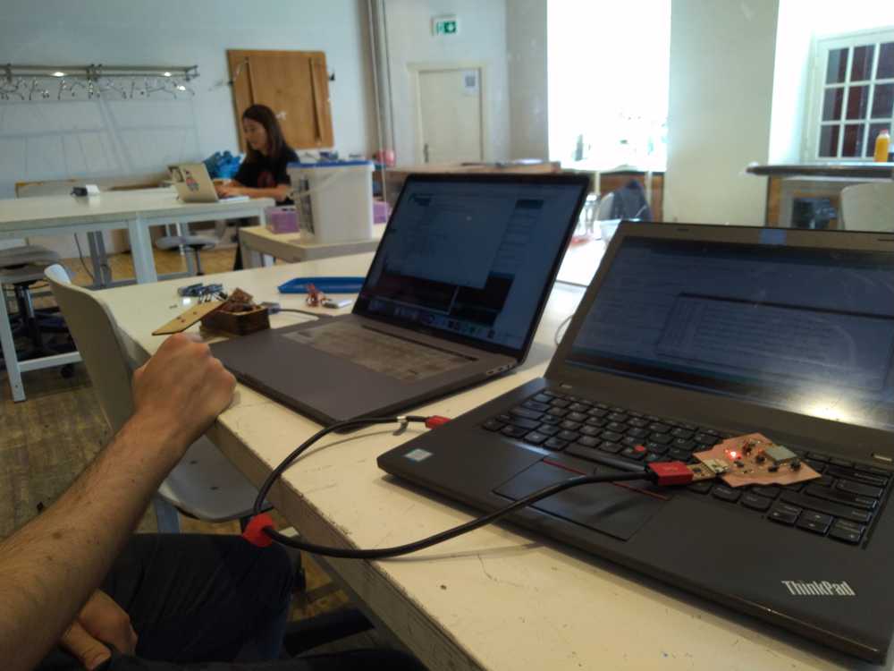
Here is our setup. Nathan’s is on the left with his device next to it. It is connected to the USB port using an FTDI. My computer is on the right with my board on top of the keyboard.
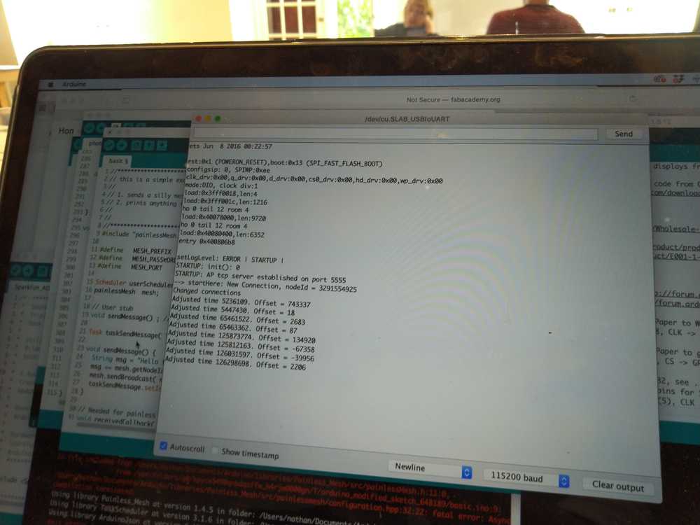
Here you can see Nathan’s serial monitor. You can see that the chip has established a network and that it sees a new node. That is my device.
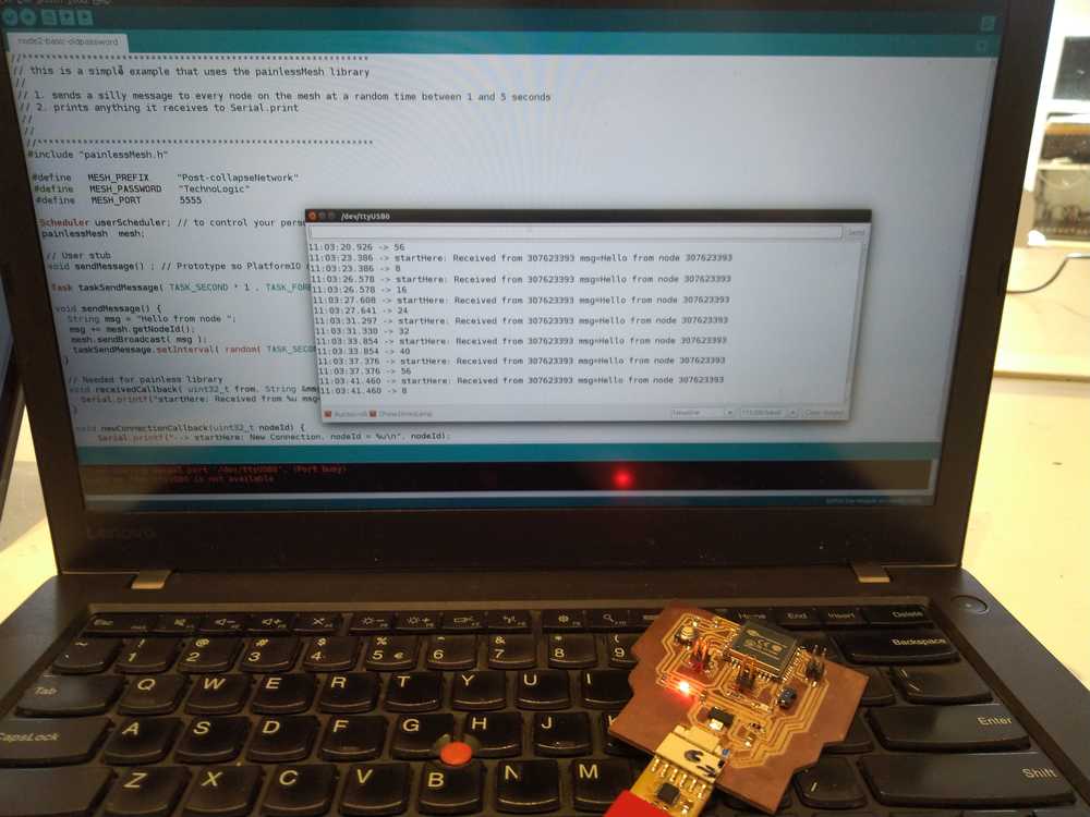
Here is my serial monitor displaying each time it receives a message from Nathan’s node.
Here is a video of the setup. We pan from my device, to Nathan’s device. Then to Nathan’s serial monitor showing that the network is established. And ending on my serial monitor showing messages being received.
What I learned
Mesh networking is a really nice feature to add to your board. It makes it really easy and quick to connect different devices. Setting up Nathan’s board was super quick. And mesh networking allows you to just keep adding boards. So you can just upload the code to many different boards and you’ll be expanding your network. I have been working on mesh networking already. But that was all done on boards of my own. It was really nice to connect to somebody else’s board. It really gives you the feeling that you are connecting to the rest of the world.
Global lecture
Today is about multiple processors. Reasons to make networks:
1. location: for people being physically in different places.
2. parallism: each processor does a single task. Make a system of linked.
3. Modularity: break your system into little modules. You can develop and debug your modules separately.
Serial bus:
RS232: client and host talking to each other.
Host and 1 node: TX and RX makes them communicate. But you can make it communicate to multiple nodes. They share the RX. The host thinks it is just talking to one RX wire.
Initially all nodes are in tristate: disconnected. They listen to the wire. Each node has hardcoded ID.
With this simple setup you can link different nodes together.
I2C device
Can be done in hardware of software.
Two pins SDL & SDA.
Asynchronous: Receiver must figure out to distinct between the separate bits.
Synchronous: Data line and clock line, clock lines tells when to need to dataline.
Each has I2C address, you need to find that out. You need to use a scanner. Looping over addresses. When I het response, I print the address.
SPI
Using MISO MOSI
Arduino had standard SPI library.
Synchronous protocol.
In circuit programming with original AVR parts. Programmer talks to chip over SPI.
SD memory card: high speed and low speed mode. Low speed uses SPI. Uses Attiny44. You need to do hard stuff for file systems.
On bigger processors you do not need to do that. ARM processor.
The faster protocol is not an open standard one and harder to program, but higher data rate.
hello.uSD.D11C.ino
A very interesting embedded distributed computing platform by the inventor of Forth: https://www.infoq.com/presentations/power-144-chip/
USB
USB grew up around RS232. You can do hardware USB.
USB has profiles, RS232 does not, you just push data down the wire.
These were buses now we move on to networks.
Networks
OSI layers:
1. PHY = physical layer: carrying physical signal
2. MAC: identify yourself
3. Network: IP
4. Transport: control flow
5. Session layer start stop sessions
6. Presention SSL
7. Application
Ethernet is hard to use. Standard way is to use modules.
Pick way to modulate.
PCM: amplitude of the signal.
OOK: on and off. Morse code like. Problem: you can’t see difference between zero and no signal.
Networks have routes. They are nut just a wire, but the network of wires are organized in routes.
DHCP: how you reuse addresses. You use unrouted address inside the local network and one internet address. DHCP server takes care of that.
UDP / TCP: say which port to use. TCP also manages the flow of information. UDP is just sending a packet. TCP checks if
UDP_slip.py: interface to assign addresses to devices.
Radio: oscilator makes signal, amplifyer sends it out, demodulate. Any radio has versions of that going on.
Antenna’s jobs: impedence matching: if antenna isn’t
There are single chip radio’s. Used to be many parts but now integrated in a single chip that takes care of all the jobs.
Nordic: RF24L01
NRFM95 can go up to a kilometer. Used for city wide networks.
ESP01 is little module
ESP Arduino core documentation.
ESP8266: can be used as radio but not much more.
ESP32: much more powerful. They use a lot of power when they are running. Sleep time is not so consumptive.