3. Computer-controlled cutting
Amsterdam, February 12, 2020
To do
Check Group assignment
At FabLab
Check documentation on vinyl cutter
- make pictures
check documentation on laser printer
- make pictures.
Make a comb: Check files Neil
Make joints: check files Neil
Research press-fit kit
Build Freecad files for lasercutter
Build Inkscape files for lasercutter
Build sticker files Vinylcutter
Make press-fit kit
Make sticker
Suggested tools:
- Electronic digital capiler
- USB 5 gigabyte is enough.
Source files
| Description | source file |
|---|---|
| FreeCAD project making celestial bodies with parametric design. | Downloadable FCStd |
| Living hinge SVG and DXF files from Inkscape for the lasercutter | Downloadable DXF or Zipped DXF and Downloadable SVG. |
| Saturn ring, sun and connection part, SVG and DXF files | Downloadable DXF or Zipped DXF and Downloadable SVG. |
| Ray for the sun | Downloadable DXF or Zipped DXF and Downloadable SVG. |
| Vinyl cutter Inkscape file logo Gr1p | Downloadable SVG |
To import the file into FreeCAD you can copy the url and drag it into the FreeCAD main window. On the left down side opens a download manager. Double click and the file wil open. Source.
| Description | link |
|---|---|
| Week overview | http://academy.cba.mit.edu/classes/computer_cutting/index.html |
| Global lecture video | https://vimeo.com/391123690 |
| Global review | https://vimeo.com/392743609/52bd47a93f |
| Recitation Managing projects and design thinking | http://academany.fabcloud.io/fabacademy/2020/recitations/Project-Management/ |
| Group assignment documentation | https://fabacademy.org/2020/labs/waag/groupAssignments/week3.html |
Machines
Lasercutter
General
Our lasercutter is a BMR CO2 laser. It’s bed measures 150x120 cm. The laser tube is in the back. The laser runs through the middle. A tube around it is filled with water to cool it. The water must be demineralized to prevent chalk from polluting the machine. There’s a white vat at the back of the machine that contains the cooling water. The read out on the panel must be between 20 to 30 degrees. If it displays a higer temperature there is a problem.
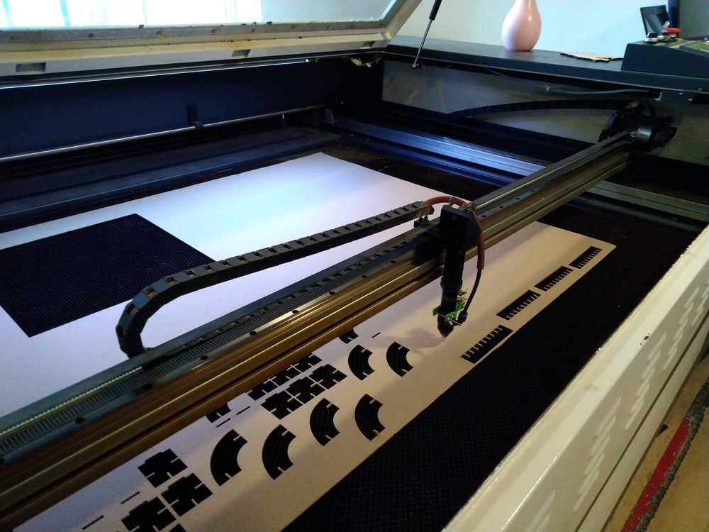 Our lasercutter BMR.
The bed or grid is the cutting area. Your material should be placed within its bounderies. When you turn on the machine the nozzle will move to its beginning position in the left upper corner. There’s a wooden block with the number 12.10 engraved on it. This block is the exact length the nozzle must be from the material. At this length the laser is in exact focus. Put it higher or lower and you wil be out of focus. This block must always be placed back in the same place, on the left top of the laser cutter.
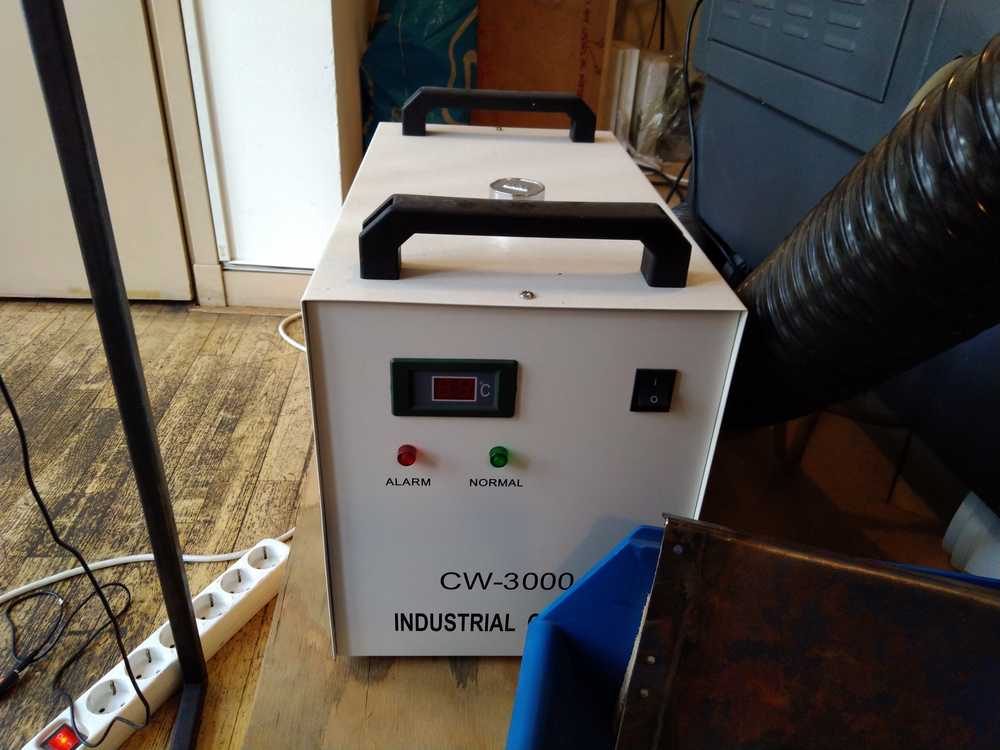 Water cooler. Temperature must not go over 30 degrees.
SAFETY
1. Close the lid
The lid must be closed when the laser is working. (The laser won’t start when the lid is open but still, never press start until lid is closed.)
2. Fire = stop + spray water
When something catches fire, hit pauze or stop and use the plant spray to put it out. There are no electronics under the bed so it can take a little water.
3. Remain in the box when job is running
There is a red box painted on the floor. You must remain in this box for as long as laser is working. Leaving the laser printer alone whilst it’s working can cause a serious fire.
SAFETY for the machine
-
Adjust laser focus manually
When adjusting the laser focus, do it manually by screwing the nozzle. Don’t do it by moving the Z-axis of the cutter’s bed. The machine is dumb. It does not know where it’s muzzle is and will crush it. -
Some materials are forbidden. Don’t cut certain materials like rubber or PVC. The fumes are too toxic.
Software
The laser cutter has a dedicated computer that runs Lasercut 5.3. It accepts .DXF and .CS2 files. It translates code into G-code which is the laser cutter’s language.
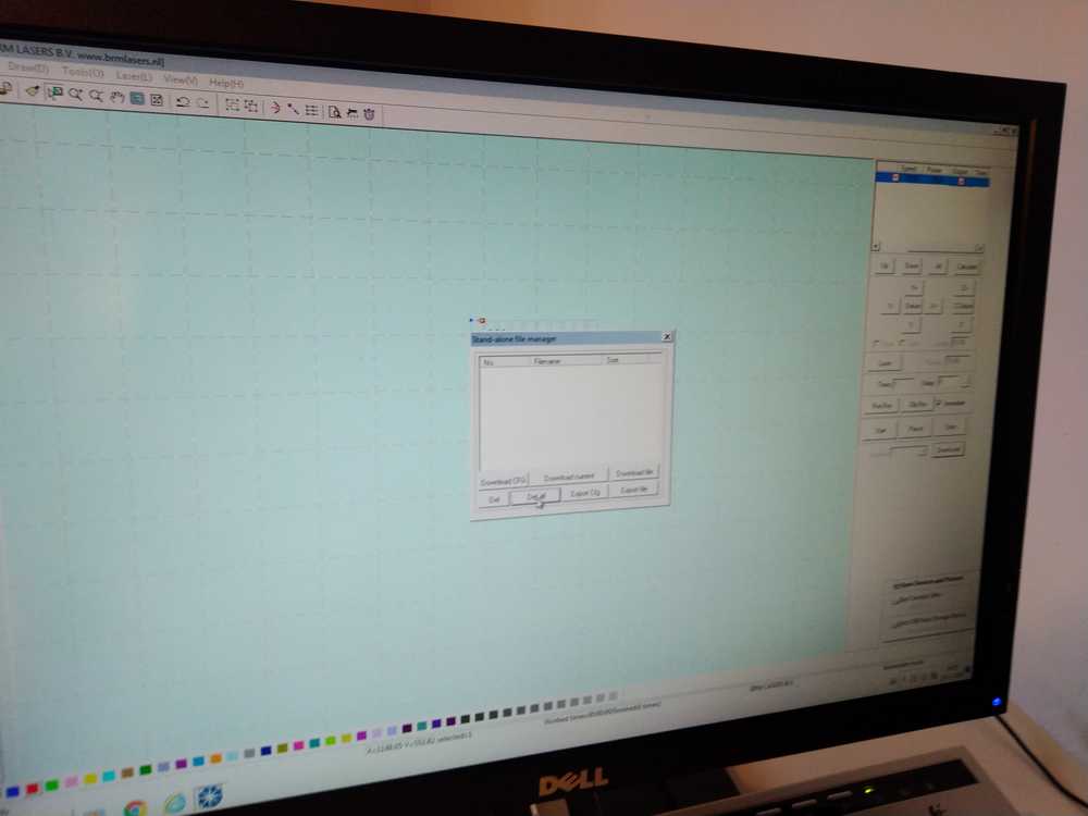 Computer interface.
Follow each of the following steps:
Opening file
1. Insert USB with your source file.
2. Copy source file to a directory in Fabfiles > 'yourname'.
3. Open Lasercut 5.3. (Blue icon at the bottom of the screen.)
4. Import file into program. .ai or a .DXF file that you can prepare in Inkscape. (Do not use open command. It must be import. Sometimes it does not work the first time. Just close program and try again. You must have switched the machine on. Only switches 1 and 2, the turn key and the green button. No need to have the laserhead on just yet. But if you don’t switch the first to buttons on, the software won’t except your design.
Fixed steps
1. Check the dimensions of the file. (The program may inadvertently change them.) Icon on the left side of the panel. Hover over the icons to read their purpose.
2. You can change the dimensions in the dimensions box. Click the 3 dots to propagate the change proportianally to all the inputs.
3. Scroll out so you can see your entire workfield. Make sure there are no objects outside of the the laser bed bounderies.
4. Zoom to all object, right click mouse.
5. Under edit click center table. If there is a warning: not within bed, you must change it in your original design program. Not in Lasercut 5,3.
6. The design has many dots. Select all, under tools click unite lines. (You get tolerance, keep on default. (0.100)).
7. Under laser click set origin. Keep default left-top. If you change it, change it back to default after for the next person.
Changing settings:
1. Select an object in your design, give it a color. On the right hand side adjust setting. You must first select the line. Then assign a color at the bottom left of the panel. Then set the settings for that color at the right upper side of the panel.
- Cut, engrave, hole (making dots).
- Speed, power and corner power. Always put corner power low at 20%.
- Output on or off. (Off means it won’t get cut.)
- You can attribute these colors in your design (Inkscape) but they must be RGB colors.
Note: There are little boards with example cuttings, left of the laser printer. Here you can read off what settings you want to use.
2. Select another object. You can give it another color to apply different settings.
3. Move the object that needs to be cut first to the top (with the arrows in left pane). Always cut the inner object first.
4. 5 squares. Always comb.
5. Click Download to machine. (Left pane, box Download.). Note: the machine must be switched on for this to work.
6. Click delete all.
7. Click download current.
Error message: communication timed out: you forgot to switch on the laser cutter.
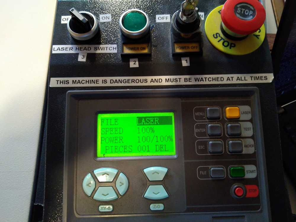 Control panel of the lasercutter. Steps 1 to 3 are clearly marked.
Machine on:
The machine is numbered 1, 2, 3, 4.
1. Power up.
2. Power on.
3. switch the laser and cooling system on.
4. Separate black machine: exhaust.
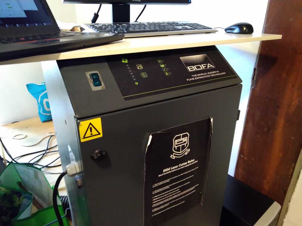 Exhaust machine to suck out fumes.
Machine settings:
5. Machine does not respond? Press ESC.
6. 4 arrows: Press xy-0 button below. Now you can move the XY-axis. 2 arrows move the Z-axis. (Do not use this to adjust laser focus!).
7. Adjust laser head Z-axis. Turn ring at top of laser head, not the one at the bottom. Use 12.10 block to measure length. Screw ring tight again.
8. CHECK IF THE LASERHEAD IS CREWED ON TIGHT. If the head is loose, don’t turn the lower ring. Turn the head itself to tighten.
9. Anchor then Enter. Placing origin in current place.
10. Test. This will show the outer path of the laser.
11. Close the lid.
Note: if test does not start. Download file again and start anew. Or press ESC. Or restart machine.
12. CHECK IF 3 COOLERS ARE ON.
13. CHECK IF 4 EXHAUST IS ON.
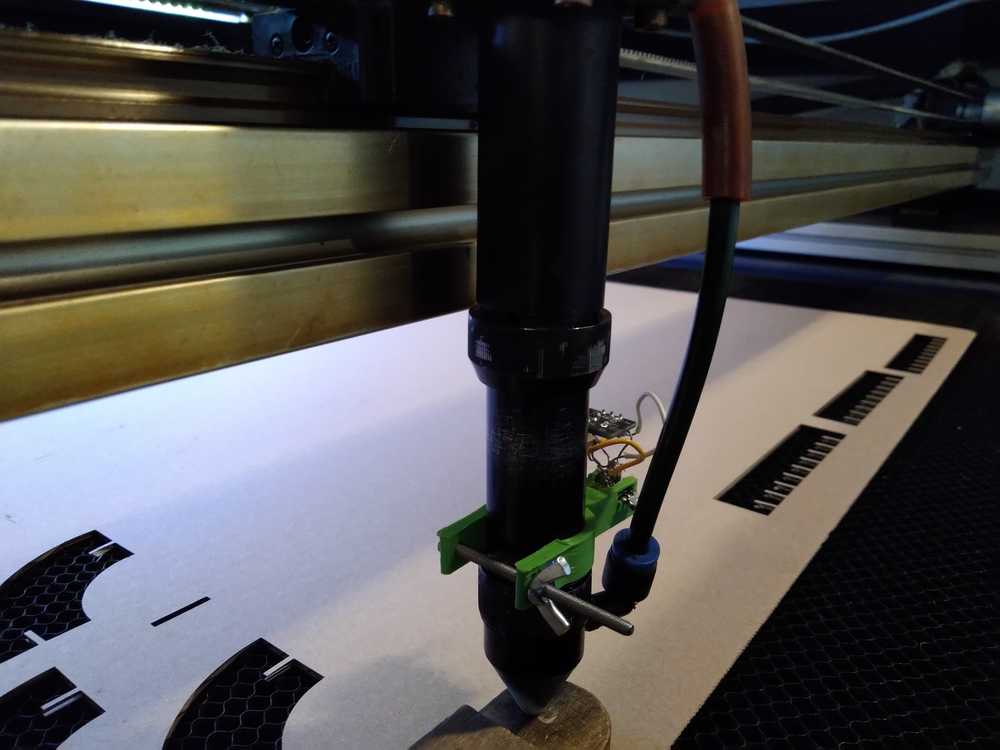 Laserhead with the ring at the top to adjust Z-axis.
Machines working:
1. Start.
2. To pauze press start again.
3. To stop press stop.
4. Emergency Stop. You may always use this. But when it isn’t necessary choose pauze or stop. It kills electricity to the machine and it does not like that.
Machine end:
5. Leave lid closed till fumes are gone.
6. Leave the exhaust on till all fumes are gone.
7. If you have several jobs you can leave on 1 & 2 (power up and power on).
7. If you have several jobs you can turn off 3 & 4 (cooling & exhaust).
8. If new job does not start press ESC and try again.
9. FINAL: turn off 4, 3, 1.
Vinyl cutter
Our Vinyl cutter is a Roland GX-24. A little knife will cut the design out of the vinyl.
- Vinyl cutter Roland GX-24*

Operate the machine:
1. Put the vinyl in from the back of the machine.
2. There are 2 rollers holding down the vinyl. These must always be placed on one of the four white strips.
3. Make sure the vinyl role is placed in straight.
4. On the back lower the handle to fasten the vinyl.
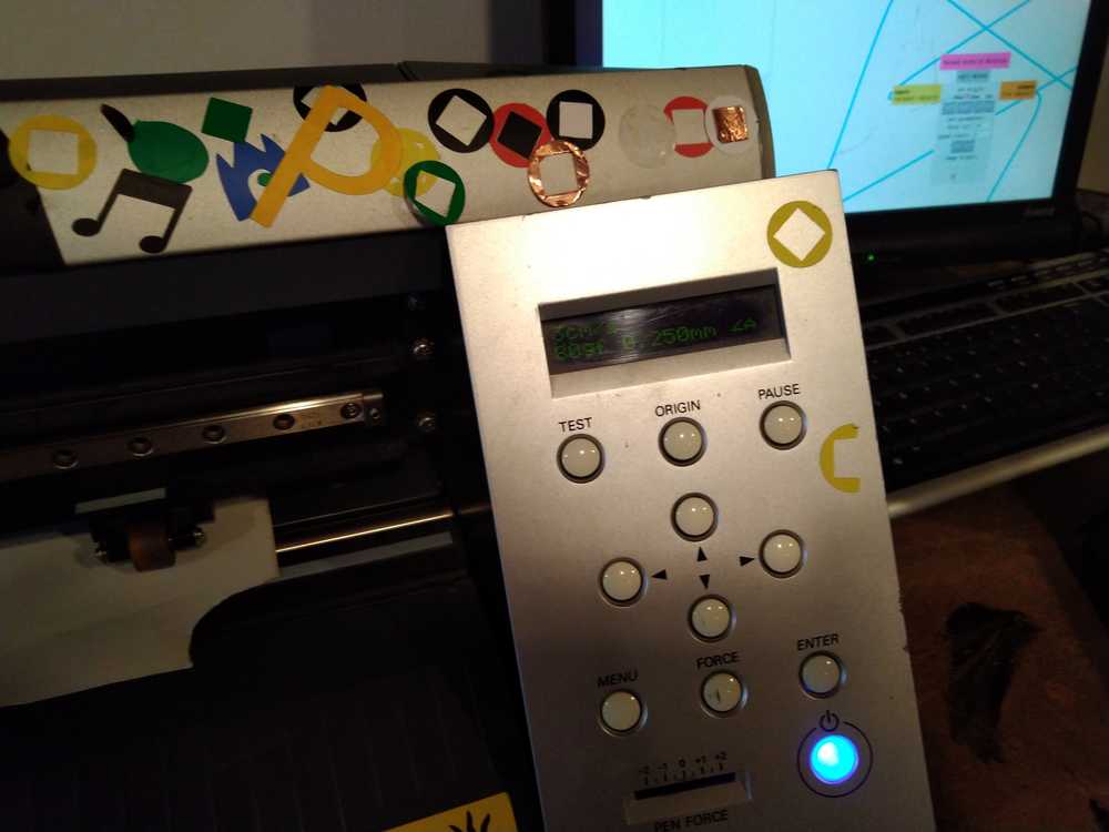
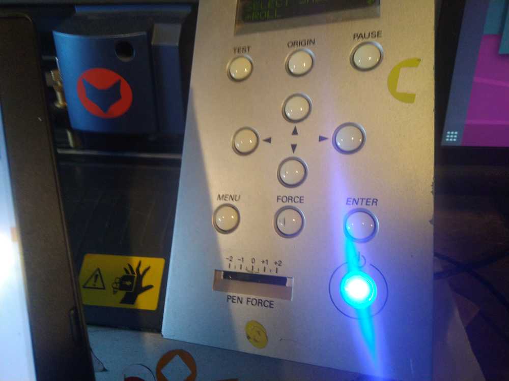
Control panel
1. Press enter on the machine. Knife aligns left.
2. Right + left arrows move knife.
3. Up + down arrow move vinyl back forth.
4. Press origin to set origin of knife. Presse till text ‘origin set’ flickers.
5. Press menu for settings. The standard settings are: 5 mm; 3mm/s for speed; 80 gforce.
6. Press test: test cut ensues.
7. G-force 80 (pressure by the knife).
8. Check your test. Pry away the 1th layer with a tweezer. Did it only cut the 1th layer?
9. Go to software.
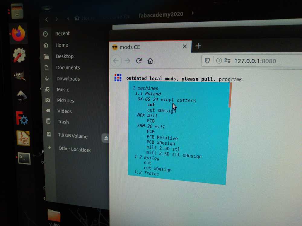
Computer Mods on Ubuntu:
1. Login.
2. Run Serial server and Mods from the desktop.
3. Clicking on Mods opens Firefox.
4. Dropdown menu choose: Programs > open program > Roland GX-24 > cut.
5. Select SVG or PNG. (you may have to move the browser window a bit. The starting point can be outside the screen.)
6. Follow the lines of Mods for different funtionalities.
7. Under Roland GX relative set the image origin.
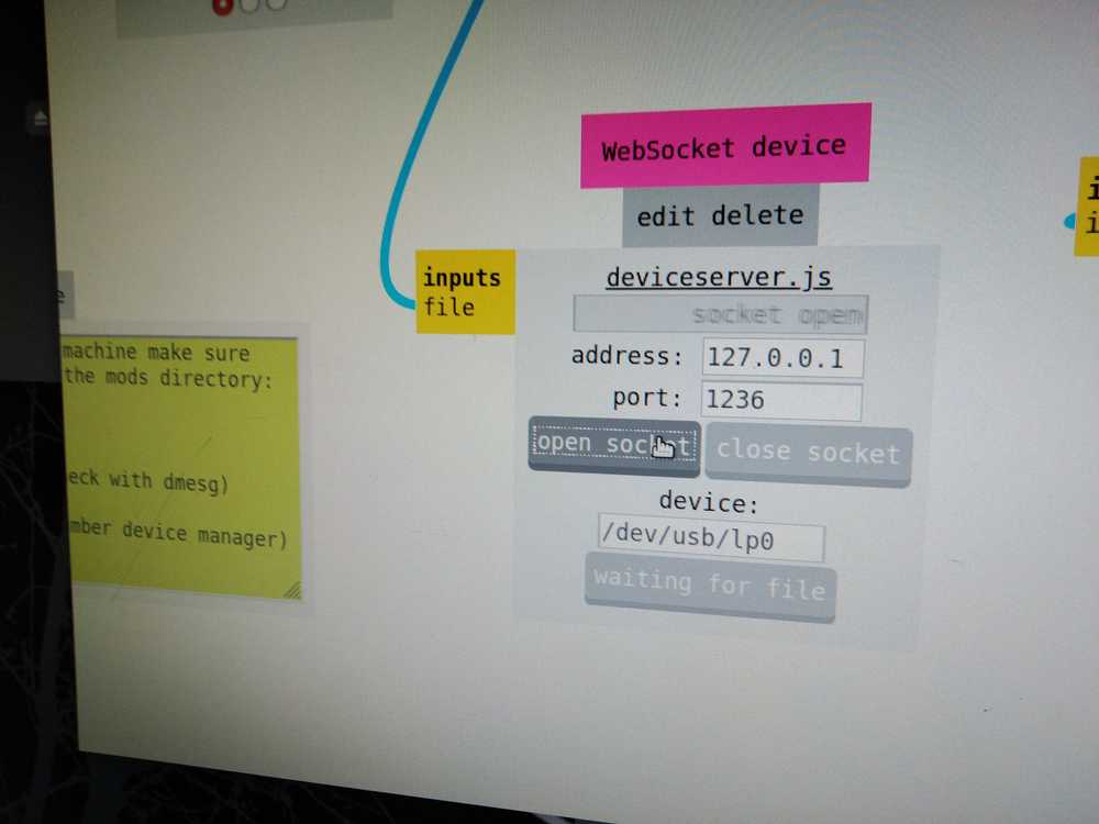
8. Go to websocket device.
9. Open socket.
9. Send file to device.
If you want to do a second file, the send file to device may not be available and instead show waiting for file. Interact with the file, calculate raster for instance. And you are good to go.
Troubleshooting
Check server port.
If nothing happens check the server port in the web server terminal. There the port said 1234. In Mods the port was 1236. Adjust the port. Proceed.
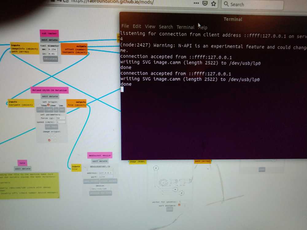 Check if the ports in the terminal and in Mods are the same.
Sheet unloaded Sheet unloaded keeps scrawling across the cutter’s panel display. The machine won’t respond to any of the panel’s buttons. This is an actual error described at the roland’s manufacturer’s webpage. It may mean the sensor of the sheet mover is dirty. What fixed it for me was moving the cutter manually. This gives also an error but afterwards the machine worked.
Computer Illustrator on Windows 7:
1. Computer is dual boot defaulting to Ubuntu. To get into Windows hit F2, F11 of F12 and select Windows.
2. Start up illustrator.
3. Copy source file from USB to hard drive.
4. Always make the cutting line 1 pixel.
5. Click File > Print. options open.
6. Do not scale: design will keep original size.
7. Placement (origin): a little cube with squares. Click the left bottom one.
8. Optionally you can go to Setup Roland preference.
9. Width > get from machine.
10 Settings you can change speed.
11. click ok print twice.
Physical work:
1. Sheer back the part of the vinyl you do not want with tweezer.
2. Transport it to transparant vinyl.
3. Stick on destination surface.
4. Sheer back transparant vinyl.
Group assignment
For the group assignment we had to ‘characterize our lasercutter’s focus, power, speed, rate, kerf, and joint clearance’. See: Schedule week 3.
For the entire description of the group assignment see our collective Waag 2020 group page.
Speed, power and kerf
The kerf is the width of material that is removed by a cutting process.
The speed parameter describes the movement of the laserhead.
The power parameter describes the output is the output power of the laser.
The offset is the amount of distance by which something is out of line.
The idea To characterize speed, power and kerf we looked at the Waag’s Class of 2019 how they did that. Rutger was our mentor for the day and we looked specifically at his documentation. We took their idea of measuring the kerf at different speeds and power settings by creating a design of a horizontal rectangle divided in 10 vertical rectangles. The horizontal rectangle is 100 mm wide. The lasercutter will cut out 10 vertical lines to create the inner rectangles. When you measure the width of the combined 10 rectangles after the cut, the sum total will be less than 100 mm. The negative difference divided by 10 will be the diameter of the curve. For instance: If, after the cut, the width of the 10 vertical rectangles combined is 96,35 mm, you can conclude that the cutter took away 3,65 mm of material. Since you made 10 lines, you divide by 10 to get the diameter of a single cut line: 0,365. When you divide this by 2 you’ll know the offset. This is the number you add to your design in order for the cutter to make the true measurement of 100 mm.
The process Harm made an .ai file containing the design of the rectangles. We then cut 4 instances at different speeds and power parameters. The result is a table with the kerf and offset of our lasercutter for different speeds and power parameters. We used wood of 4 mm. You can do this test again for other materials.
Wood 4 mm
| Total size | speed | power | total after cut | result | number of lines | kerf | divide by both sides | offset |
|---|---|---|---|---|---|---|---|---|
| 100 mm | speed 30 | power 50 | 98,63 | 1,37 | /10 | 0,137 | /2 | 0,0685 |
| 100 mm | speed 15 | power 100 | 96,35 | 3,65 | /10 | 0,365 | /2 | 0,1825 |
| 100 mm | speed 30 | power 100 | 97,68 | 2,32 | /10 | 0,232 | /2 | 0,116 |
| 100 mm | speed 15 | power 50 | 97,51 | 2,49 | /10 | 0,249 | /2 | 0,1245 |
focus and joint clearance.
This was done by Nathan, Rinke and Hyejin and it is documented on the (group assignment page).
Focus
The focus of the laser cutter is where the laser beam is the smallest. It has a narrow waiste in the middle and tapers out above and bellow that. There is a little wooden block in the FabLab (always keep it in the same place at the left side of the lasercutter!) that measures the exact distance for perfect focus. You can manually adjust the Z-axis of the laser head.
Nathan researched how to measure the focus of the laserhead. He and Hyejin performed this test. They placed an piece of wood at an angle under the laser cutter and had it cut a line. The result was rather impressive. The cutting line goes from rather wide in the out-of-focus setting, to very narrow in-focus. It was interesting to see the focus makes such a difference.
joint clearance
Joint clearance: The distance between mating surfaces of a joint. We talked a lot about the kerf and the offset. That’s because we couldn’t get our heads around it. In the end I think we got it. You measure the kerf. Then you divide it by two. That’s the offset. This ofset you add to the cutting lines of your design. Otherwise the cutter will eat away material that you need.
rate
The laser doesn’t actually cut a line. Rather it burns a series of little piercings. The rate parameter determines how far apart these holes are spaced. A high rate places them close to each other to the point where they overlap. A low rate places them further apart. We were not able to test this parameter as the rate of our lasercutter is fixed. Not physically but by degree. One shall not mess with the rate parameter.
Individual assignment
Idea
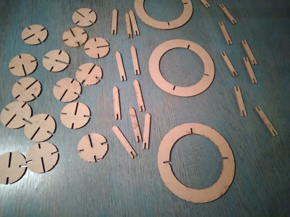
For my assignment I will make a celestial bodies press-fit kit. Two round bodies fitted into each other become a 3D representation of a star or planet. There will be four objects: a circle for the celestial bodies, an arrow that serves as rays for the sun. And rings that serve as the rings of Saturn and a connection stick that attaches the ring to the planet.
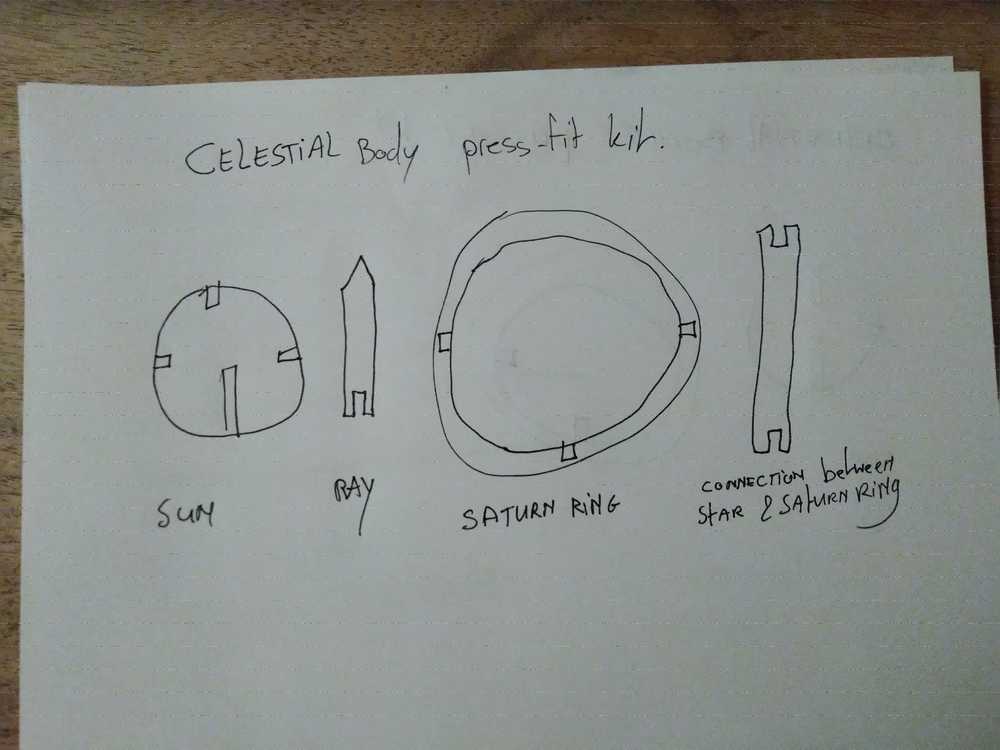 Saturn is a planet, not a star!
Before I could start the actual cutting there were many things I had to do first. Making the designs in Freecad, exporting and manipulating them in Inkscape. I first describe the things I have done. Way below is the outcome of the assignment.
Inkscape
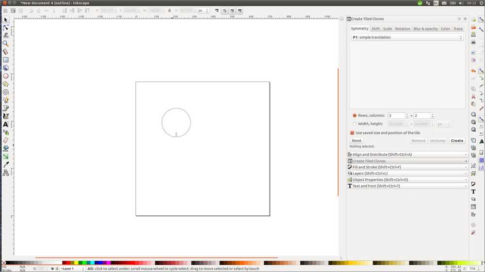
I started out with an Inkscape tutorial on parametric design. I haven’t done any Inkscape yet so it doubles as an Inkscape beginners tutorial.
1. file > document properties. Opens new file and let’s you manipulate the properties. I’m choosing 100 mm x 100 mm.
2. + - zoom in, zoom out. Or use right side icons magnifyer glass to switch between canvas view and object view.
3 # toggle grid.
4. Draw rectangle.
5. Fill and stroke: Shift + CTRL + F or menu > object > fill and stroke.
6. Stroke style: defines width of the stroke. I put it on 0.025 mm.
7. Using a small width may render the object invisible. Under view display mode outline toggles outline on.
8. Settings for x-y axis and width and heighth are at the top of the workbench. Select object to manipulate.
9. Create clone: ALT D or edit create clone. A Duplicate won’t change. Clone changes identical to original object.
10. Making groups of clones: tile set. Left pane shows options.
11. Note: set original off the table to distinguish it from the clones. Add text saying ‘Key’ above it. (Using text icon).
12. Goal: Making a grid to use the 4 cloned rectangles as slots.
13. Draw square.
14. Distribute square: object > align and distribute.
15. Left pane: options. align to page, object, etc. I choose align to page.
16. Center on vertical and horizontal axis. (Icons).
17. Take 1 clone and center to page too.
18. Moving clone to edge of square: set align to first selected. Click outer square. Shift click on clone. Hit align left edge of object to right edge of ancher. Then hitalign right sides (icon). This may seem redundant. But this is necessary for scaling later. Otherwise scaling up will all go into the right direction. While what you want is scaling in all wind directions.
19. Do it again for second clone. Select clone. Select page. Center to axis. Select first selected. Align to achor (goes outside the square to center of page). Align left edges.
20. Third clone to center. Rotate 90 degrees. (icon upper left side.)
21. Back to clone original. Scale up. Hold CTRL Shift to keep both ratio and center alignment. Here something odd happened. Scaling would often result in scaling in one direction off center. Also all rectanlges would scale to the right side. I rotated a rectangle to have it scale to the left. I hit Shift and Shift CTRL. Now it did scale keeping center alignment. Not sure what the difference is.
22. Remove the outer rectangle. (Select, delete).
23. Group the 4 rectangles. (Select all. object > group).
24. Now the 4 rectangles can be cloned as well. Drag outside table under key. Clone them, make tiled clones again.
25. You can no manipulate the rectangles as a group. Or manipulate the initial rectangle.
26. Make another rectangle. Center on page.
28. Center one of the cloned group on page as well. Make them same size.
29. You can group and clone this too.
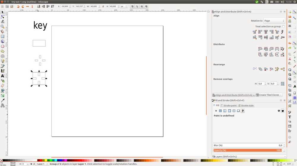
Outcome of tutorial: Started with the one rectangle at the top. These you align to the outer lines of a square (bottom). When you remove the square you have a an element you can use to make a grid.
There was no table in the tutorial as I had expected. Having come to associate that with parametric design. So I looked up another tutorial on Github.
1. I draw circel, holding CTRL key, align to page.
2. Make radius parametric. edit > XML editor.
3. A split pane appears. Left side shows attributs. Whenever you want to make an attribute parametric, just add the namespace prefix parametric: to it. In this case: parametric:r.
4. You can use value or mathematic expression like 3 * (a + 50).
5. The paramteric:r becomes a new attribute. The original r attribute remains. This is a fallback for programs that can’t read parametric.
I then realize that this is for a specific additional add-on type thing for Inkscape and abandon this tutorial. In the end I don’t do the parametric design on Inkscape but in Freecad.
FreeCAD: Making a parametric press fit design
About parametric design
There does not seem to be a single definition of parametric design. Most explanantions on the internet say that it is a means of designing using parameters. You can define your own parameters. When you change the value of the parameter the change will propagate throughout the design. On engineering.com a second feature is described: It is a way of modelling whereby you use 2D sketches to make 3D designs. Each sketch is a part of the total model. You build one part on top of another building a dependency tree. This is why it is also called history-based modelling because every new part is dependent on what came before it. The model must resolve every step that is made in the design to build the model. The website quotes Matt Lombard saying: ‘You can think of this method of model building like a computer program. You give the computer instructions for every step, and it executes those steps for every time the model must be rebuilt.’
In FreeCAD, parametric design is executed by defining parameters in a spreadsheet and attributing a value to them. You then assign properties to the parameters consisting of at least a name and a measuring unit. When you change the value of the parameter this will propagate throughout the design where ever you have applied the parameter.
Starting out in FreeCAD
I started out with looking at the joints.FCStd that Neil mentioned in the global lecture. To import the file into FreeCAD you can copy the url and drag it into the FreeCAD main window. On the left down side opens a download manager. Double click and the file wil open. Source.
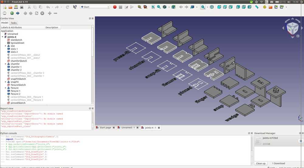 Neil’s Freecad project of different types of slots.
There is a short description on using spreadsheets on the Freecad wiki.
First off I’m making the chamfer slot. I am going to remake what I’ve seen in Neil’s joint.FCStd file. This is just to get an idea of how parametric design in FreeCAD works. And how to get it to a lasercuttable design.
- New project
- Partdesign
- New part
- New body
- New sketch, close sketch
- Spreadsheet workbench, new spreadsheet.
- Enter name of parameter in 1th cel (LengthX), enter value in 2nd cel (40 mm). Right click on value cell, click properties. Enter alias and enter display unit. Close spreadsheet.
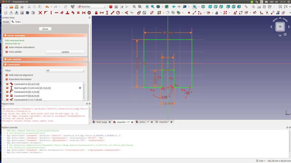
- Open sketch. Draw rectangle. Set origin with equality constraint.
- Add horizontal constraint. Click circel in constraint box. Type ‘S’ for spreadsheet. Type ‘L’ for length. Click LengthX. The value of the spreadsheet is now the constraint of the X-length. Name constraints for convience.
- I make three lines to form the slot. I apply equality to the parallel lines. Go to spreadsheet and enter value for slot Y-length. Apply in sketch.
- I am left with 1 degree of freedom. The slot can move over the Y-axis. I click the lower outer points of the slot and the Y-axis. Apply symmetry. Resolver says overconstrained. I apply the same action to the upper 2 points of the slot. This is accepted.
- I use trim edge to remove the outer slot line.
- Applying 2 90 degree lines for chamfer connecting slot Y-axis to the lower line of the outer square.
- Applying equality constraint for chamfer lines.
- Applying chamfer line length to spreadsheet and apply in sketch.
- Chamfer lines turn out not to be fixed to slot Y-lines. Redo.
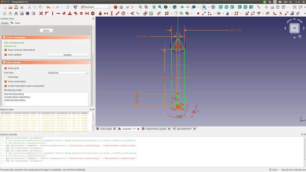
- Applying angles to chamferlines. I want to define these in the spreadsheet. But I can’t seem to be able to apply degrees as a measurement unit. I look at Neil’s sketch of the chamfer. It seems he has used a ‘normal’ constraint (not in the spreadsheet), rather than a parametric one for the angles. I will in any case do that.
- With the trim tool I want to take away the surplus material of the chamfer. But when I do that new degrees of freedom emerge.
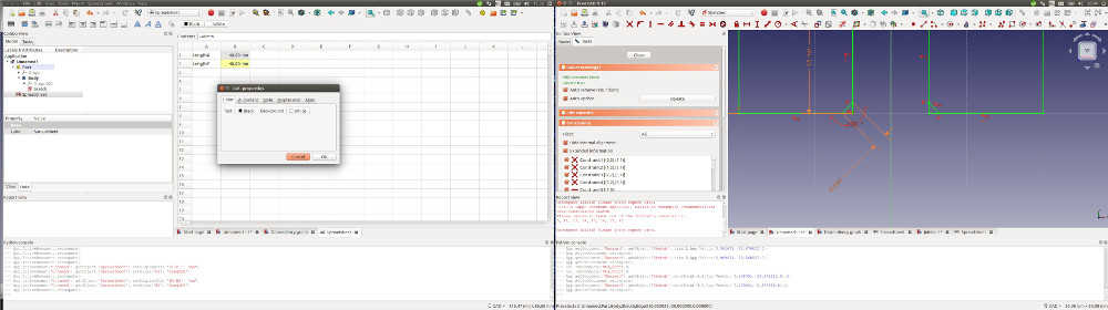
Left: the beginning of my spreadsheet. Right: working on the chamfer corners.
- I click 2 points of the Y-lines of the slot and add the slotXlength constraint.
- I want to trim the Y-line of the chamfer but I can’t. I think it is because they are part of the Y-line constraint of the Y-line of the slot.
- I remove Y-length constraint of slot.
- Add new Y-length parameter to table: slot Y length minus chamfer. And apply. Does not work. It takes the entire line.
- I hit CTL Z a couple of times. Not exactly sure where I am viz a viz the steps in my sketch. I remove the left lower X-line from the chamfer now as well.
- I now have 2 degrees of freedom. One of which is that I can move the slot up and down. huh? A constraint that kept it anchored to the lower X-line must’ve gotten undone by the operation. Is this a solution to my problem? The chamfer is now totally free from unneeded lines.
- I apply the coincidence restraint to my two disconnected lines. Resolver says: first remove constraint 19. Okay, I will. Now coincidence takes. The chafer lines and slot lines are connected. But there is 1 degree of freedom left. They can move up and down.
- First I change the parameter of the Y-line of the slot from slot-Y-length to slot-Y-length-without-chamfer. I want the slot to be 15 mm in total.
- I add another parameter: chamfer-width. I apply it to the 2 most outer points of the chamfer. Now I have a fully constraint sketch. Pfew!
- Oh wait this is wrong. When I change the slotXlength in the spreadsheet, it does not change because chamfer width forbids it. I delete chamfer width and instead add a contraint to the the little angled chamfer leg.
- No, this does not work either. If I want to change the slot fit I first have to release the chamferleg constraint.
- Finally I end up with my test chamfer piece.
 Test to make a chamfer
Importing model into Inkscape
Rutger told us you can’t export from FreeCAD directly to the lasercutter. You must go through Inkscape because it produces files the cutter likes better. Then save as DXF in inkscape using standard R14. You can make adjustments in Inkscape too if you want. I am going to add a kerf, or rather an offset for the kerf in Inkscape. Reason is that if the offset is wrong, I don’t want to go back to FreeCAD because then you’ll have to go through Inkscape again.
An easy but crude method is path> inset or outset. This decreases or increase your entire object. You can reduce the increments the inset and outset tools make: In preferences > behavior > steps. So you can use this if you need to adjust for the kerf for the entire object.
Here is a pdf I found about adding offset in Inkscape. I haven’t tried these methods yet. Because I have not yet tested my files on the lasercutter. (It’s sunday.) Having looked at both programs better since writing this, I think that FreeCAD might be the better program to change the offset. It’s where I worked parametrically after all!
Now I am going to import the file in Inkscape. There are several settings you can choose as you import. Translate to G-code for instance. For now I’ll just press ok.
Assignment: Celestial body press-fit kit
I am going to make a press-fit kit with which you can assemble celestial bodies. I wil make a sun with rays and Saturn with its rings.
I make the sun in Freecad using the method described above making the chamfer based on Neil’s example. I have managed to make the slot but when I try to add the chamfer I hit a wall. It seems impossible to connect a line from a straight line to a circle. I search the internet for answers to no avail. I use the trim tool to remove the line between the circle and the slot. The line remains. The Python console give Gui.runCommand('Sketcher_Trimming',0).
Because of this trouble of adding lines to the circel, I did not add chamfers to the suns slots. I did add chamfers to the other objects.
 Beginning of the sun with the slot in the bottom. I was not able to remove to line of the circel and the rectangle to provide for the opening of the slot.
I import the sun into Inkscape and remove the slot barrier there. I used the edit paths by nodes tool. Second icon in the left side tool pane:
1. select object.
2. click nodes tool
3. Convert selected item to path. (icon upper tool pane)
4. Select the line you want to remove. (Between to nodes.)
5. If no path is given when you click, you can also add the nodes yourself with the icon node tool.
6. Delete segement between nodes. (icon).
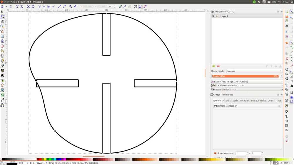
The sun is not finished yet. It needs four slots. I try to accomplish this in Inkscape. Spoiler alter! I will fail.
The plan is to clone four suns, rotate the clones so there is a slot on each side and them merg the four clones into one object.
1. Center 1th clone with object > align and distribute.
2. I rotate the 2nd clone and also align to center. The sun now has 2 slots.
3. My idea was to do path > union to merg the 2 objects together. This does not work. The objects can merge. They just won’t do it when on top of each other.
Another road to abandon…
Back to FreeCAD
I go back to Freecad. Maybe I can copy the sun in the sketch. Rotate the copies and apply them to the initial sketch. Creating multiple slots that way.
Copy can be found under Sketch > Sketcher tool > copy.
Copying an object within a sketch is possible. But I realize that it is hard to rotate it. In previous tutorials I’ve seen that to rotate an object, you basically rotate the sketch. Since I want to have four objects (suns) in four different positions, this also does not work.
I look online on how to copy a sketch within one project. I find ways to copy sketches in your mega-FreeCAD file to other projects. But not within the project itself.
(Oddly, a day later I just tried copy/paste while a sketch is selected and that works.)
Copying in FreeCAD
Between projects:
Here is a good explanation about how to copy elements between projects. I document it because it can come in handy some other time.
Source: Freecadweb
‘One way would to do this would be as follows:
With your mega FreeCAD file open do File > New or click the icon,
Now you’re in the new document,
In the hierarchy tree select what you’d like to copy into your new document,
Do Edit > Copy (or Ctrl + C),
Click the button in the pop-up window,
Do Edit > Paste (or Ctrl + V) to copy them into your new document,
Now save your new document using a new name.
To import it into FreeCAD use File > Merge project.’
Inside a project: select sketch copy paste. (Maybe use the icon if CTRL-C doesn’t work.)
Instead of copying sketches I proceed to add the slots manually.
 Sun with four slots
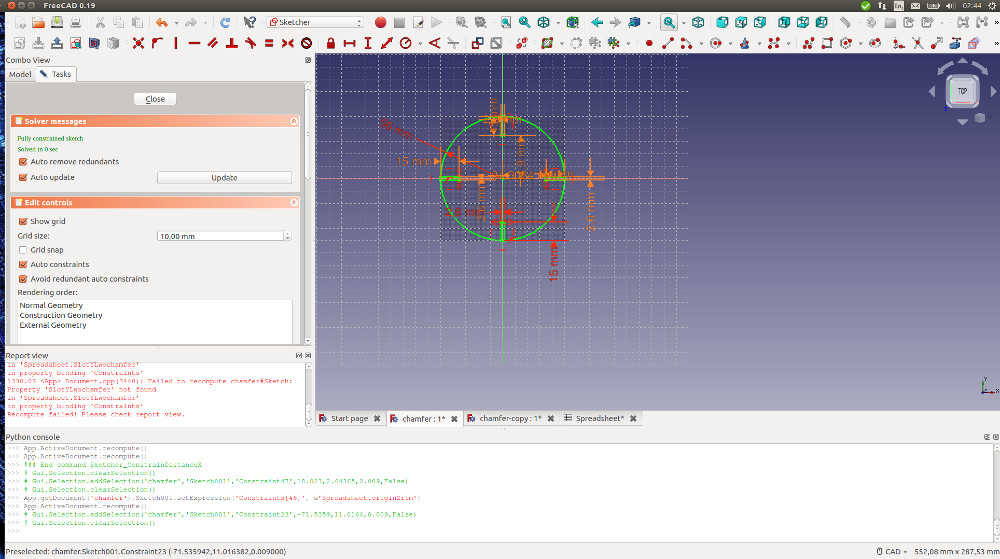
As a final step, I want to change one slot into a longer slot that spans half the radius. This has as a purpose that 2 2D planes of the sun can be slotted into each other so that they become 3D.
Here I run into trouble again.
I change the length constraint of one of the slots to a higher value to make the slot longer. But nothing happens.
I suppose that another constraint is preventing it from taking on a new shape. I delete a constraint that fastens the slot to the circel. The new paramter length still does not occur. Strangely I have one degree of freedom that lets me move the line of the circel. This is what I tried to accomplish hours earlier when trying to open a hole for the slot. But I do not now how this happened, and the object had 1 degree of freedom which is not good. So I want to refasten te circel line.
I try to fasten it back to the slot line with the coincident constraint. No dice.
I hit CTRL-Z multiple times. For a while nothing happens and then suddenly the circel line is fastened again. Even more: the length of the slot has taken on its new value.
I have no idea what went wrong. And no idea what fixed it. It is not very satisfying to have it solved this way. But I should’ve taken the unsatisfactory win. Because I think I’m now finished. But then I see that all these operations have affected to slots. They have rotated.
 Two slots have unintentionally rotated.
I fall back to CTRL-Z again. Suddenly the rotated slots are back in the right place. The object is now fully constraint and the new parameter has taken hold. I am done!
But wait…
The new parameter of the slot should have it run all the way to the center of the circel. But it only comes half way. I then realize my circel is too big. I wanted to give it a 50 mm diameter using the diameter constraint. But instead I used the radius constraint. My circel is twice as big as I intended.
I change the diameter to the right value. The slots omve out of place but that is logical, I constrained them relative to the axes.
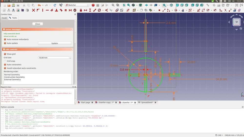 Slots no longer in the right place after changing the diameter.
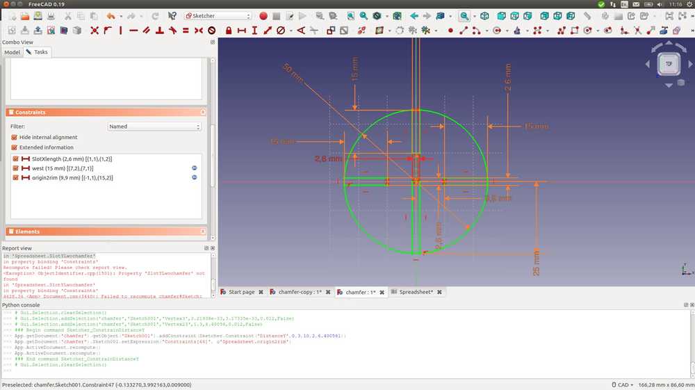
To solve this seems straight forward. Just adjust the value of the parameter that defines the distance to the axes to the new diameter. In the table I change the value from 34,9 mm to 9,9 mm. This is what parametric design is all about right!
But not in this case. Changing the parameter value does not change the position of the slots. I delete the length constraint. Maybe the slot can’t move because of other constraints. But after deletion I can move the slot freely up and down along the Y-axis. A vertical constraint fastened to the Y-axis should do the trick. It doesn’t.
But then I see in the report view: 175.54 <App> Document.cpp(3440): Failed to recompute chamfer#Sketch: Property 'SlotYLwochamfer' not found
in 'Spreadsheet.SlotYLwochamfer'.
I see in the table that this parameter is gone. Maybe a result of the many random CTRL-Z’s I applied. I write the missing parameter anew in the table. That works. Now the solver recomputes the newly given value of 9,9 mm. Looking back at the pictures I took for documentation, the missing parameter error has been there for quite a while already. The report view signalling in red trying to warn me. Sorry FreeCAD, I wasn’t paying attention.
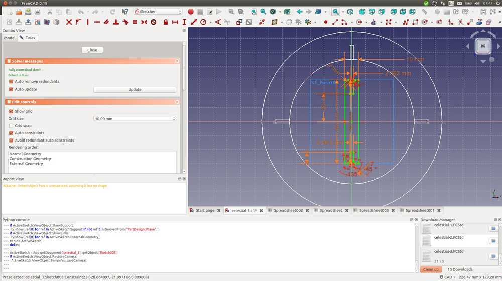
So now that is fixed. All Ihave to do is to apply the 9,9 mm constraint to the last remaing slot that has a degree of freedom along the Y-axis. I want to use the origin to rim parameter (9,9 mm) that I used for the other slots to fix it onto the circel’s outer rim. There I used the fix horizontal distance constraint applying it to the Y-axis. I’d like to do the same for the other slot using the X-axis. But I run into the error ‘select one line or two points’. So I select the origin point and 1 point of the vertical line. This works. Now my sketch looks like this.
Back to Inkscape
I Export as .DXF file from FreeCAD. I the sun into Inkscape. I remove the lines that block the opening of the slot with the nodes tool as described above. The slots and the circle are interpreted as two different objects or lines. Interesting. You can do stuff with that.
 What FreeCAD painstakingly constraints, Inkscape joyously messes up.
Then I realize the slot depth of the one longer slot of my sun is too deep: 15 mm on a radius of 25 mm. More than half. Going to adjust to 10 mm in FreeCAD. Origin to rim parameter must then also be adjusted from 9,90 mm to 10,3 mm.
More errors: 265.791 <App> Document.cpp(3440): Failed to recompute chamfer#Sketch001: Invalid type 'NSt7__cxx1112basic_stringIcSt11char_traitsIcESaIcEEE'
in property binding 'Constraints'
Attacher: linked object Part is unexpected, assuming it has no shape.
I close without saving. Sun is back to before the unable to recompute. But I do not know how to change the slot length now without reproducing this error.
I delete the origin-to-rim constraints.
I change the parameter of the slot length. Error message: part is unexpected, assuming it has no shape. So appearantly I can’t change this parameter because I have made a mistake elsewhere…
Deleting slot length parameter from one of the slots. Adding new parameter to table. Same error message. Searching online does not yield any insight into what it means. Error message keeps popping up but I succeed in redoing all the constraints by making new parameters. Now the slots are 10 mm and lie on the edge of the circle again. It must be exported to Inkscape again to remove the slot entrances.
After I do this I export to .svg. I look at the file in the image viewer and see that there ain’t no sun at all.
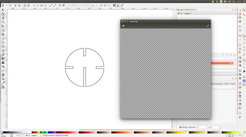 No sun.
It turns out it was placed outside the page border. I export image as .PNG. Then open in Gimp to convert to .JPG. Now I print the image to get a better idea of its dimensions and to determine how long the rays should be.
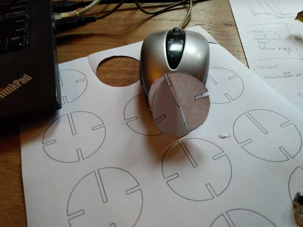 First tangible result
Next up making a ray to shoot out of the sun. I would like to use the chamfer block I made earlier as the start of the ray. But I would also like to keep the chamfer block. So I try to copy the sketch and copy the entire project so that at least I have a backup. But I can’t accomplish either. If I copy sketch with all its dependencies, my entire project is duplicated. Including a new spreadsheet. I probably do not want to separate spreadsheets. Copying the Sketch without its dependencies makes FreeCAD crash multiple times. To get a move on I decide to sacrifice the chamfer from my first test. I have exported it as a .DXF file. But I will no longer have it in FreeCAD as a separate sketch. Alas.
Reducing slot length to 10 mm by removing old parameter and applying new parameters I made for the circle. Lengthening the original chamfer and adding a triangle for that ray of sunshine feeling.
 Ray
Ray
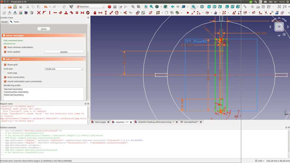
Now I have a ray and a sun. Next up the Saturn ring. Back to freecad. New sketch on top of the sun sketch. Two circles bigger than the sun will become a Saturnal ring. The ring has three slots.
 Saturn ring with three slots
And lastly the connection element. This will be used to fasten the saturn ring to the star (sun). I use the ray I made earlier, remove the point and add another slot. Both slots have chamfers.
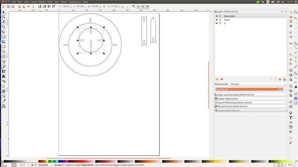
And finally we end up with a sun element, saturn ring, a ray and a connection element in Inkscape.
Lasercutter
I uploaded the Inkscape .DXF file to the lasercutter. The settings I used are speed 30 and power 50 bacause this resulted in the thinnest kerf in our kerf test. When I tested the circumference the laserhead would make, it was clear the objects had somehow become much bigger. I crudely adjusted the size of the objects in the lasercutter software. Decreasing size by one order of a magnitude. Now everything would be out of bounds. But it was just to try if the file would work at all. It did! But it came out too small as expected.
I imported the files into inkscape again. Making sure all settings were set to millimeter. Exported and lasercutted again. Now the objects were the right size.
The slot width was almost good. It would fit but had a little bit of wriggle room between the slots. But ‘almost’ would probably not pass the Henk test. The thing I did wrong is that I used 2,6 in my designs. I thought that Rinke had calculated that for the right size when accounting for the kerf. But I had remembered wrong. We want a 2,6 mm cut but for that we need a 2,436 measurement in the design.
So I went back to Freecad and adjusted the slot size to 2,436 mm. And it worked. Parametric design worked! In a few minutes all my objects (which were in separate sketches) had the new slot size. Import to Inkscape, export to DXF file. On the second run the slots were good. Although I made another version of the suns. They have the long slots for fitting them together. I want that to be really tight. A new measurement of 2,336 did the job.
Error message
On the first try I did the machine gave a ‘soft stop’ error each time I tried to do a test. Henk debugged it. He said: ‘there will be one little bit wrong and the machine won’t work. Most times it’s because there is something outside your cutter bed in the design. But not this time. First he restarted the machine. Then he restarted the machine and computer. Then he went to the machine panel. Pressed Anchor. Usually you press okay. But going down in the menu with the arrows lets you choose reset. That solved it. To debug machines ‘you have to think like a machine’, Henk advised.
Another thing that went wrong is that the laserhead fell out as I moved it over the axes. During a test thankfully, not during cutting. It turned out the laserbed Y-axis was so low that the periscopic function of the laserhead was all the way extended to the point it almost fell out. And then it did fall out. Check the laserhead before using the machine. Is it screwed on tight enough?
Another mistake I made is that I did not separate the three versions of my cuts. So now the ones with the correct slots are intermingled with the older imperfect once. Keep it tidy!
My design almost came out fine, accept that I forgot to remove a line in my rays. They were decapitated. I redid the design removing the line and did another lasercut run. That worked.
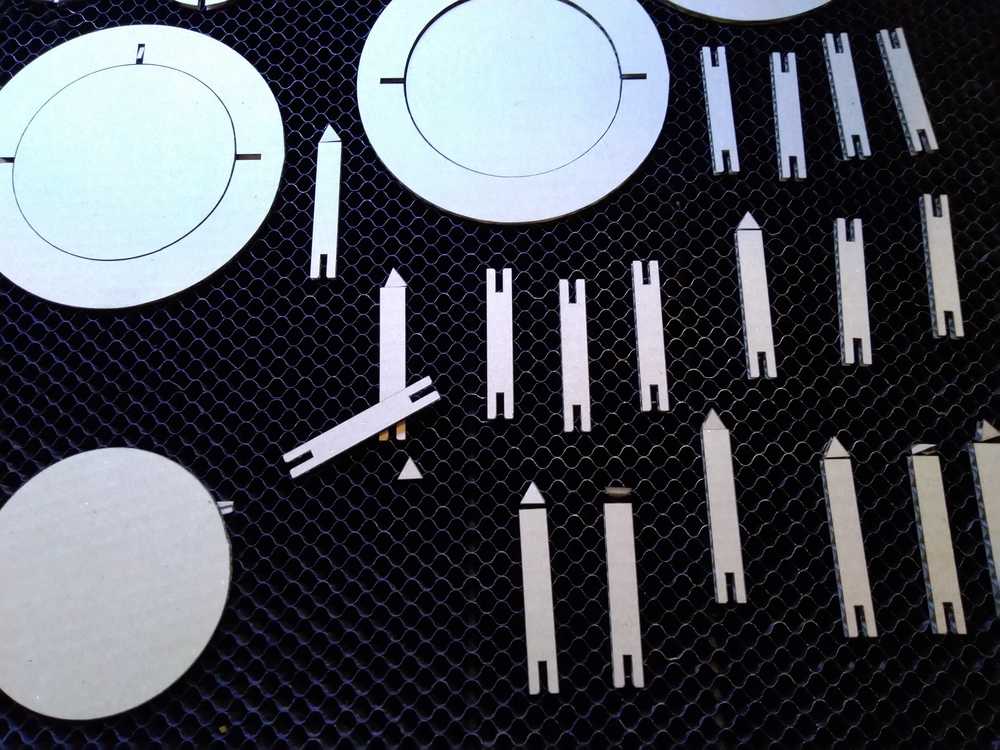 Decapitated rays
I started assembling my kit.
 press-fit kit
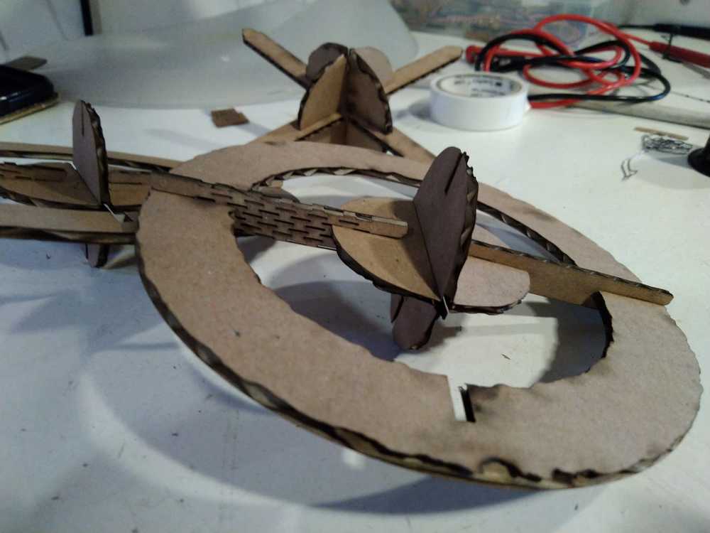
It works. But. I made a design mistake. The connectors that must fasten the Saturn ring to the planet can’t be put in place. Once you put it in on one side there is no room to slit the connector into the other slot. Oops!
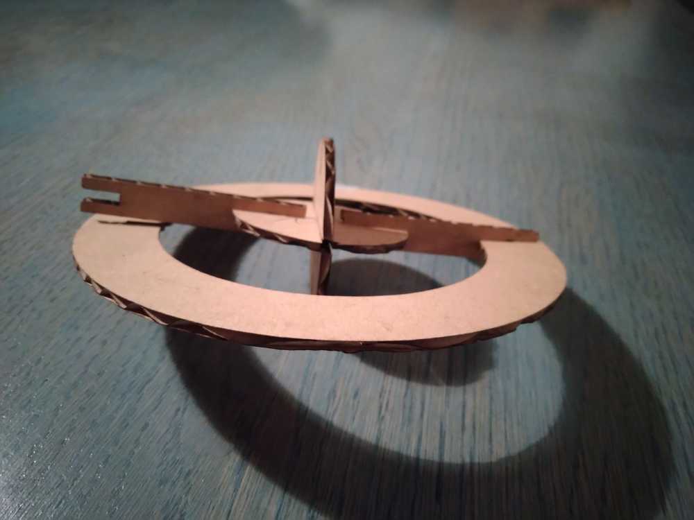 It presses but it does not fit!
Jules from the FabLab came up with the idea to apply a living hinge to the connector stick so it can bend.
The result of the first iteration of spiral development
Living hinge
I made the living hinge using an Inkscape extension which can be found here. For Linux: download and extract the package. Copy the living_hinge.inx and src/living_hinge.py files to the proper Inkscape directory. You can find the right directory in Inkscape by going to edit > preference > system. Here under inkscape extensions a path is shown. In my case: /usr/share/inkscape/extensions. I copied the entire directory here, not just the files mentioned above. I also copied the .inx and .py files in the directory.
Now the extension is available in INkscape. You might need to restart te program. Make a rectangle in your design. Then click extensions > render > living hinge. You can change the settings. It is well explained in the window what the different settings mean. I used settings: cut length: 5,00; gap length 3,00; separation distance 1,0.
Then shift click on your object. and shift click on the hinge. Choose: path > object to path. I’m not sure if that is a necessary step, but doing that worked. Then click path > combine. Test by moving the object. You want the object and the hinge to move. But not the rectangle you placed to orient the hinge. This stays behind when you mpve the object. Delete the rectangle. Now export to .DXF and you can cut.
When making your design keep in mind the direction of the card board currocation (the riblles in the middle.) It’s better to rotate the object in the design, then to have to rotate the cardboard on the lasercutter bed.
One mistake I made was with copying the directory to the Inkscape folder. I used the command cp. But when copying a nested directory you need to use cp -r. (for recursive).
I had to do three tries making the living hinge. In the first one there weren’t enough hinge cuts. Also the cuts were in the wrong direction of the cardboard. You have to take into account the currocation and don’t go against it. The second one bend okay, but it turned out the slot length was to long, There was 2 mm to much space and it could be moved back and forth in the slot. Henk did not accept.
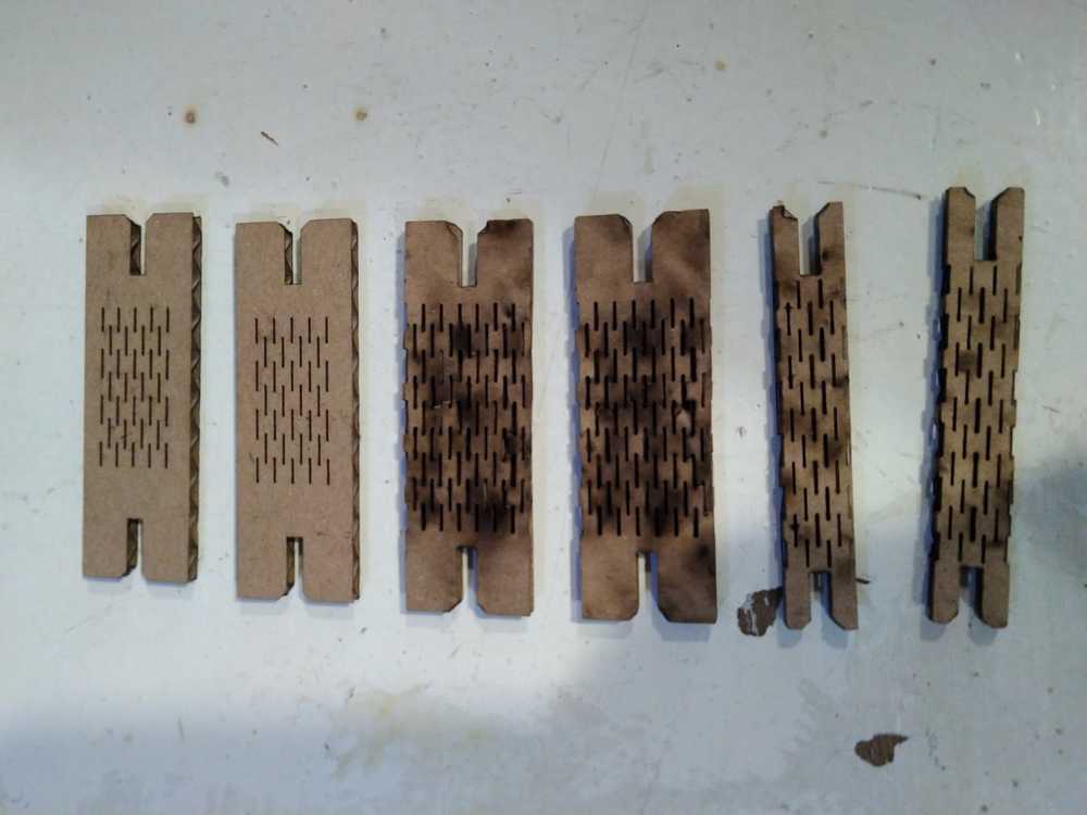 Three tries needed.
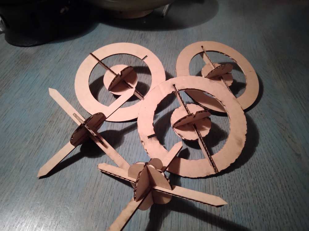
 Press-fit! Finally.
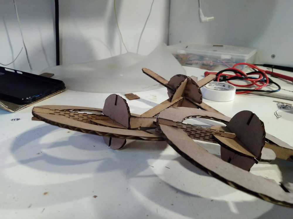 Final result of the second iteration of spiral development.
On the third try I decided to make the hinge width thinner. It looks better. And finally it was a true press-fit.
Making sticker on the vinyl cutter
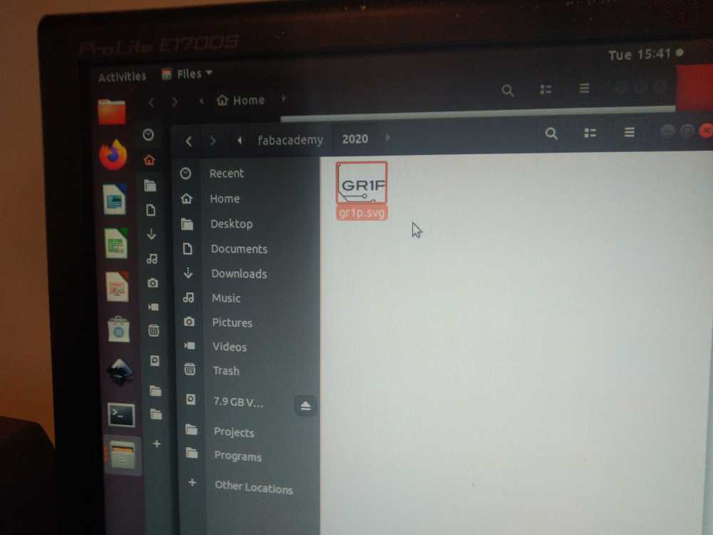
I want to make make a sticker for our Gr1p foundation because we have a nice logo but we don’t have stickers yet.

Gr1p logo
I start with yet another tutorial. This one explains how to set up you SVG for the vinylcutter in Inkscape.
I load up the .SVG file of the logo in Inkscape. Don’t run it of the USB stick, copy it to the computer’s harddrive.
Put on the Vinylcutter
I make document 50 mm x 50 mm. The logo file as well. Make sure width unit is set to mm. First I try Illustrator it does not really work. It cuts out some of the silhouettes in the design as a single line. I make the line thicker in Inkscape. Then it cuts silhouettes but crosses over lines. This cutting up the silhouettes. I try a PNG file instead of SVG but Illustrator is not having it.
In both instances I used the standard settings: 5 mm; 3mm/s for speed; 80 gforce.
I switch to Mods.
There are two icons on the desktop
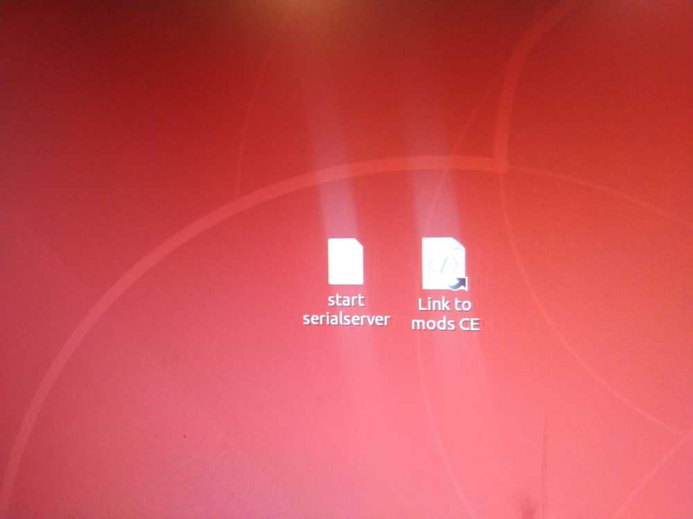
First click start serial server. The serial server opens in a terminal. You do not need to mind that anymore. Then Link to mods CE.
Mods opens in the browser. Right-click your mouse.
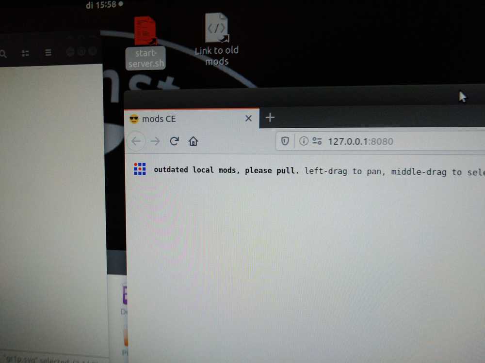
A little panel opens. Click programs.
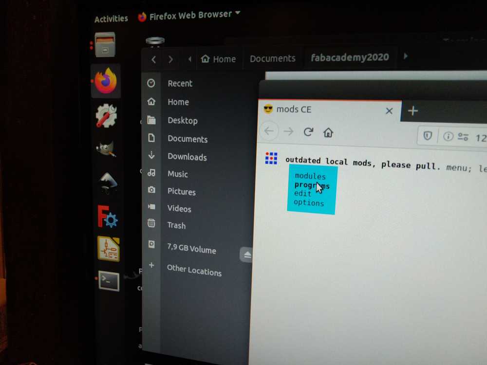
Then click open programs.
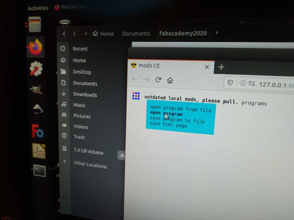
Choose Roland GX-GS and click on cut.
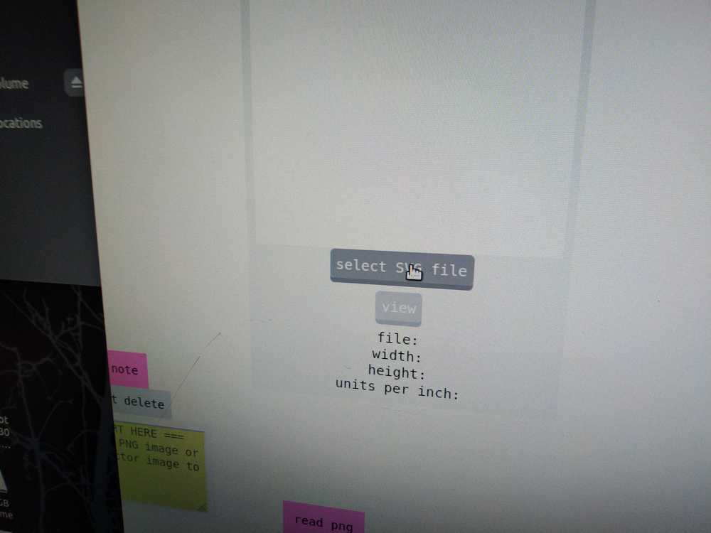
You can either select an SVG or an PNG file.
Next you follow the lines. Each line leads to a new module. You can choose to make adjustments in each module. For instance, in the bottom module you can adjust the g-force and speed per centimeter. I changed these from the one on the picture to 5 mm; 3mm/s for speed; 80 gforce. In the one above you can adjust tool settings. There are other modules too, like one to invert your picture. But I don’t use any of those.
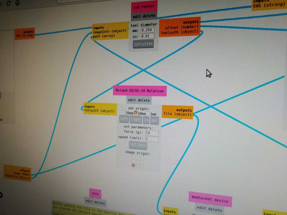
Instead I go to the final module in which you send the file to the vinylcutter. This is the websocket module. Open the socket and send file to device.
It runs in one go with the sticker exactly as I want it. It looked complicated when we got the explanation about it but it is actually super easy and versatile. Thanks Mods community!
 The sticker on my laptop
Sublime
I switched from Nano to Sublime to do my documenting. Nano did the job well but there were a few features that got in the way. Mainly having a good overview of longer texts. Therefore I am now trying Sublime for my documenting to see how that goes. In terms of overview it does better so far.
Mistakes I made
I made a lot of mistakes during Freecad design and working the machines. These are all described in the process. There was not a big overarching mistake this week, like in the previous to weeks in which I lost hours focusing on the wrong thing.
This was not so much a week of big mistakes, rather a week of walls. I ran into a lot of walls which took me a lot of time to overcome and then blam! there’d be the next wall. I am not sure if I could’ve done things more effiently or if I should’ve thought of other ways to go about it. FreeCAD just has a steep learning curve and you have to stay at it. I don’t see I short cut I could’ve taken to speed up the work or make it better.
This was the hardest week so far. I worked a lot on the assignment. And it’s still pretty crappy. More impotrantly, I am not even sure if I will be able to accomplish the assignment. Today is Sunday, so tomorrow I will test my designs on the machine. It’s been a long time since I’ve been in a situation where I really don’t know if you will accomplish what you set out to do. In my normal live, I realized this week, I do stuff I know how to do. It can be hard or a lot or scary. But I’ve done it before and deep down I know I can do it. This week… This week I wasn’t sure at all that I could do it. Still ain’t! It is an interesting experience. Not a very pleasant one though, haha.
Do I have a bad influence on machines? The vinyl cutter would not go off after I used it. Henk had to unplug it from the mains. The laser cutter gave a soft stop error and later it dropped its laserhead when I looked at it…
The above I all wrote on Sunday after a weekend struggling with designing. On Monday I went to the lab and after a lot of trial and error created the first iteration of my spiral design. That day I was joyous. So over all it wasn’t such a bad week as I described on Sunday. All days taken together it was fun.
Henk told us we should upload source files to our documentation. I added the sourcefiles in an MkDocs folder and linked to them. It worked locally. But Git keeps giving 404’s. I linking in Markdown style, with html:


[downloadable file](/files/week03/test/gr1p.svg)
<a href="/files/week03/test/gr1p.svg">test</a>.
<a href="./files/week03/test/gr1p.svg">test</a>.
<a href="../files/week03/test/gr1p.svg">test</a>.


[Screenshot](../files/week03/lasercutter/connect-staurn-sun2.dxf)
This is working:
[Downloadable FCStd](../files/week03/celestial/celestial.FCStd)
Except for DFX files. They become code in the browser. FCStd does as well, but that you can download by dragging the link into you viewer in FreeCAD.
I looked at documentation Rutgers documentation but he seems to use just a HTML link and I tried just that. It works locally. Not remotely.
What I liked
It was the first week we did a group assignment together. It was really fun working together. For this week’s group Rutger should be included too. He explanined the machines. In a single day we learned how the machines worked and were able to cooperatively get some work done on it. A very nice day.
I’m starting to discern a FabAcademy pattern. On Wednesday we’re introduced to a new technique. It’s really impressive and cool but I don’t really see myself actually applying it. On Thursday during the local lecture we’re taught how to do it and do a group assignment. In about 24 hours we’ve gone from cool theoretical idea to having collectively applied the technique. On Friday I start to go on my individual journey getting my first bearings in the different things you need for the assignment: design programs, material knowledge, working the machines on your own, etc. On Saturday is design day and usually the day I am certain I will never be able to do this assignment. Ever. On Sunday evening there is a design that might actually work tomorrow in the lab. At 10 a.m. tomorrow, I’ll be done! On Monday in the lab, reality is a bit less pliable than theory and you spend the day trouble shooting. But at least you understand what you’re trying to fix and how to go about it. At the end of the day, you have a result. Tuesdays then are for the next spirals of your development. Now you actually feel like your on solid ground. This is fun! let’s make some awesome things with this! And then it’s Wednesday and it all starts again.
Global lecture
This week we are trying out 2D cutting. Here is the list of tools we can try out.
Mods: Machines have print drivers from the manufacturers. But these are all different from each other. They often have settings hidden in several layered menu’s. Neil therefore created mods that lets you handle all machines and all settings are visible.
Vinylcutter: You can use the vinyl cutter for cutting electronic circuits. Someone made a self-flapping crane just using the vinyl cutter. You can make radio antenna’s. Wheeding: don’t pull the material upwards but sheer it by pulling it towards you.
Lasercutter: mind the kerf and offset. Look into the FreeCAD files for the comb and different joints.
Cardboard bend test: when it curves it is good. When it knicks, not so much. It is nice material: environmentally friendly and low-cost. Good for prototyping.
Local lecture
There is an online system for booking time on the machines. We received our logins over email. Stored in
Keepassx. When the machines are explained you need to take careful notes. You need to be able to use the machine based on your documentation.
Using a new technique: they want you to explain it exactly. So with FreeCAD: describe exactly how you did it step by step. After that you can refer to that. Show the machine and the software. After that you can refer back to it.
Lasercutter: We play with two settings: power and speed. Too much power, material burns. The laser will take away a couple of mm on both side of the cut. There are different ways to solve the problem. By changing the settings on the machine. You can also design with the curve in mind and add an offset in the design. F.i., kerf is 0.1 you make your design + 0.1.
Parametric design: make an organic shape. It is trickier to make. Make your design fully constraint. Place origin in the center. Parameters: place them in the parameter table. Give them a name. You can give a name and type in the name and it will show up in the dropdown. Make them useful names, not line 001. There is a difference between parameters and constraints. Parameters you can change, constraints are set hard in the design and must be changed in the design manually.
Figure out perfect slot size. A cool tool to do this is to make a comb. Measure wood for it thickness. Make a few different offsets. Make 2 combs and test how they join together.
File types and programs
DXF it is an open standard. 36 different open standards. Not all exported DXF versions are exportable to closed source. You have to find the right DXF. Prepare files in Inkscape or Illustrator. Exported files from Fusion often do not work. Make sure to remove the lines you don’t need in your design. You can make designs in FreeCAD export them as DXF. Then import into Inkscape. Inkscape files work better with the lasercutter. You can make further adjustments to the file in Inkscape. Then save as DXF in inkscape using standard R14. This one has been known to work on our lasercutter works.
In Inkscape: new menu > robo master type (than the size will remain the same). In illustrator, save as illustrator file: .ai file. Get a menu, select export, different types CS2, untick all the vinkjes and then export.
Write something in inkscape. This is not yet a vector. With vector every shape is a little dot. To make design a vector: Setting object to path in the dropdown menu will make a vector out of it. Now the design can be cut. You can also use raster f.i. to make picture on the wood.
Inkscape has add-ons that expand the program. Interesting is the add-on to create living inches.
Lesson on machines
The lasercutter is in focus. The waiste is exactly on the menu. Play with defocus, this can be interesting for thicker material because the cutting will otherwise not be straight. Engraving is possible with the laser cutter
Substractive manufacturing: removing material (f.i. lasercutting). Additive manufacturing: adding material (f.i. 3D printing).
Make a logical step by step overview of what you do. Write down whole process. From making design, how you exported, where you imported, the software versions of the programs, which software is used on the machine, how you prepared the in software, how you put on the machine, document machine settings (speed, power, pressure of the knife, etc.) Document every step. Take pictures. You must be able to use your documentation to use the machine even months from now. You can check other people’s documentation for inspiration.
Local review
Feedback on documention.
- Design files are missing. Make a directory of downloadable files. Sort them by week. And then you add a link to it. Try:  Max size per week 5 MB (100 MB divided by 20 weeks.)
There are also no design files in group page
- setting: also write down you
Place a table on the top of the page with all the source files you need to add.
Regional review
Advise: When you do parametric design. Check immediately if you can change the values. It’ll safe you time later. - Use spell checker.
Global review
This part was added in week16 for the global review of my documenation. The question is if all the elements of the celestial bodies I made documented in the source files. I remember it being a mess in terms of project files in week03 and also that I had trouble saving things in FreeCad. So I was not surprised that files were missing. So I checked what I made and where I had stored it.
At first I could not find them and I looked into converting DXF files exported from FreeCad back into a FreeCad project file. A process I describe below. But just when that finally sort of worked, I found my original files back. They are hidden in the project file. I’ll describe where they are.
I made five elements in Freecad for the celestial bodies.
1. The Saturn ring
2. The sun
3. The ray of the sun
4. The connection stick that connects the Saturn ring
5. A living hinge
In the source file table there is one FreeCad project file. The one with the .FCStd extension. The other files are DXF files. These are the files exported from the FreeCad project which - by way of Tinkercad - can be fed to the laserprinter.
When you open the .FCStd file, it opens with the Saturn ring. On the left hand side, in the upper panel, the different elements of the project are listed. Half way down is an element called sketch001.
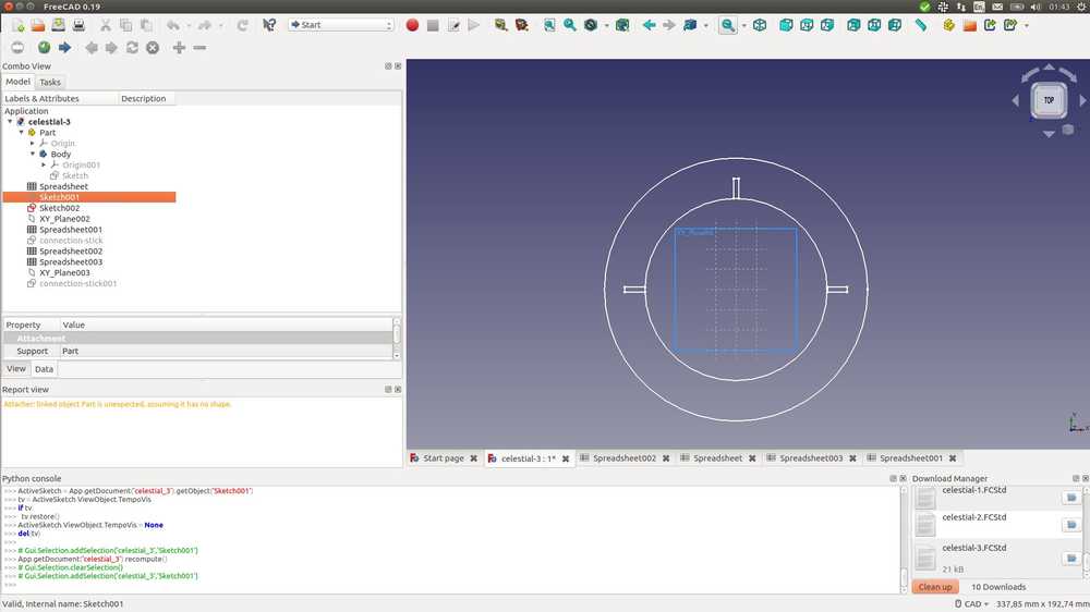
When you click it you open the sun element.
Further down the list is another sketch named ‘connection-stick’.
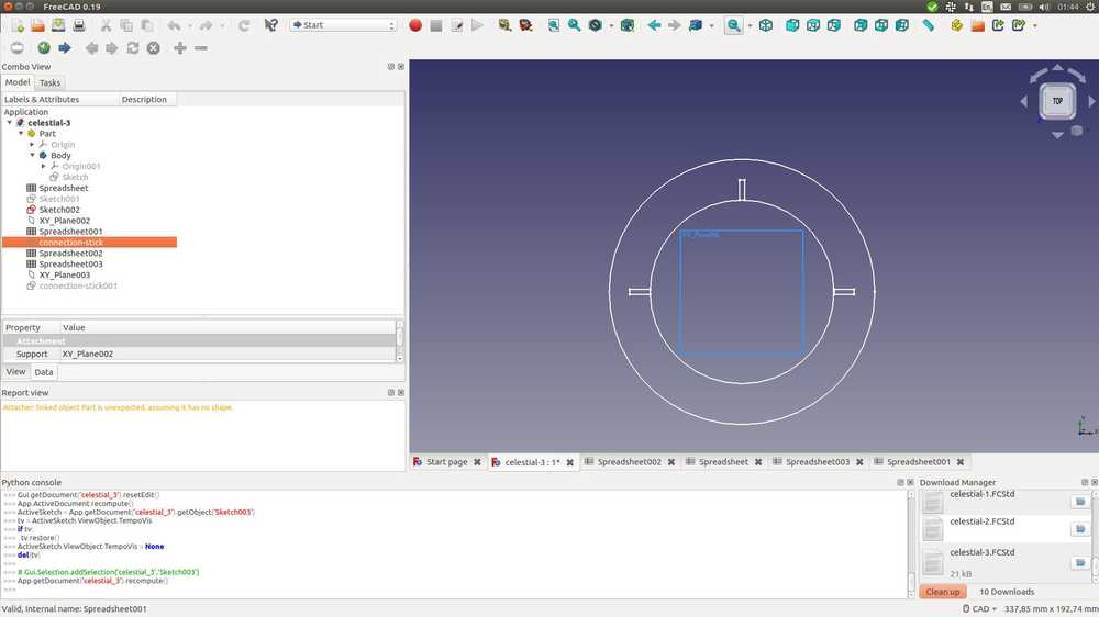
Click on that and the connection stick model appears.
All the way down is another sketch named connection-sketch001. This is the ray of the sun. It is called connection-stick because it was a copy of the connection stick but with a point instead of a second slot.

The living hinge was not made in FreeCad. It is the connection stick that was further manipulated in Inkscape to add the living hinge.
Before I found the models back, I looked into importing DXF files into FreeCad. I have many DXF files saved so if I could turn them back into FCStd files I’d have my 3D designs back.
As with all things FreeCad it is not straightforward.
First you have to enable the ‘import DFX files’ feature in the settings: edit > preferences > import/export (icon on the left) > DXF (tab at the top). Here you can enable the feature. Set create to sketches. Source Freecadweb.
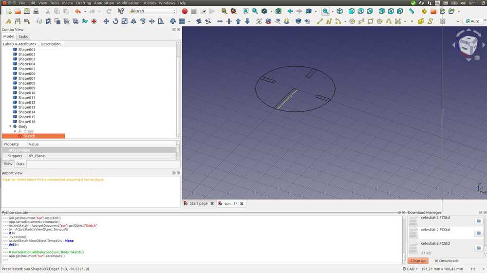
Source for the next steps is also Freecadweb. Then go to the FreeCad main window. Select the Draft workbench. Import the DXF file > import. You’ll get a bunch of shapes in your left hand panel.
Select all the shapes by clicking the top one holding SHIFT and then clicking the bottom one. Then click the icon that changes drafts to sketches.
 Source Freecadweb.
The sketches will be placed below the shapes. So scroll down to find them.
If the conversion results in multiple sketches, go to the sketches workbench and click merge sketches.
Then go to the Part Design workbench, click new body. This opens up a new panel. Choose one of the three possible planes. Usually you want X/Y plane. The sketch will now be encapsulated within a new body. Still in Part Design click validate sketch from the top menu Part Design > Validate sketch. Finally, click pad from the same dropdown menu. I had gone through all this when I found my original sketches back.
This is what it looks like in the draft workbench. You see a list fo shapes in the left hand panel, and at the bottom the newly created sketch.
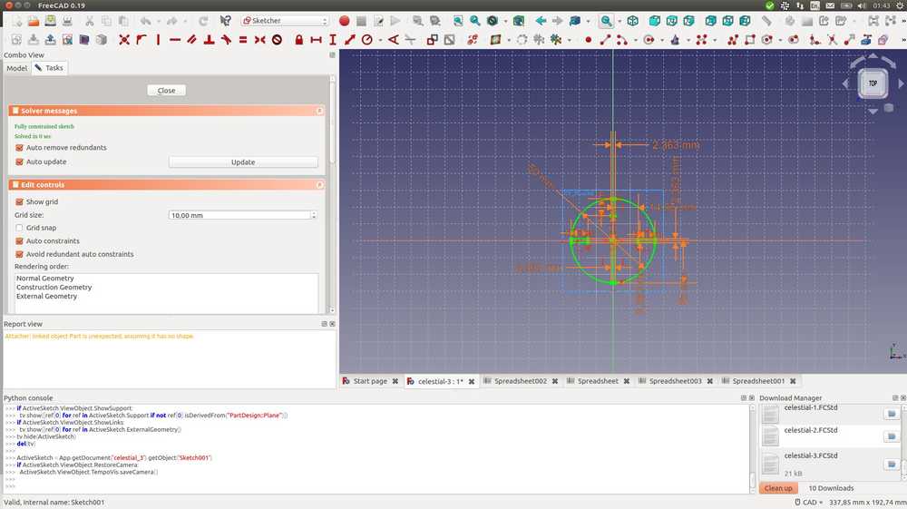
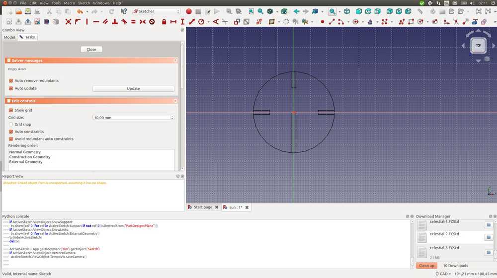
This is the project file in the Sketcher workbench.
It does not look quite as detailed as the original project file so I am really happy I found them back.